The Benchmark Demo
The surfacing demo being benchmarked is of a shaver, where two images of the shaver are inserted into perpendicular planes and used as a reference to create the body, a revolved cut for the switch at the top, shelling out the body, then split the body and add fillets.
Here’s the video of how this is done in Inventor:
[youtube https://www.youtube.com/watch?v=xbAtmG8taVs&w=854&h=510]
Here’s the video of how this is done in Solidworks:
[youtube https://www.youtube.com/watch?v=9rprIGlDUvE&w=854&h=510]
Benchmark Results
As you can see below the difference in the two is clear and the results are not as close as you would expect.
Speed
The surface demo was completed with Inventor 51% faster than the same demo in Solidworks.
Around the 15 minute mark, in the Solidworks demo, the demonstrator is 3D Sketching and instead of constraining the sketch, swaps the file with another file created earlier with 3D sketches constrained, so the gap would have been greater. I didn’t really care because by that stage the surface demo with Inventor was already completed.

Browser Tree
One of the main reasons why Inventor did it so quickly over Solidworks was that it didn’t require the same amount of planes, sketches and features to create the part file. Inventor had 57% less in the browser tree, 57% less planes, 64% less sketches and 50% less features.
Less planes, sketches and features provide benefits such as easier modification the file later because you can isolate and narrow down what you need edit to achieve your desired result and file size is also reduced, which may lead to greater computing performance.

Surface Quality
Let’s take a look at the two finished surfaces and see what the differences are.
Visually, the Inventor model looks rounded and the Solidworks model looks boxy with sharp edges.
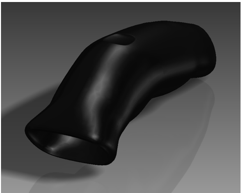
Autodesk Inventor 3D Model
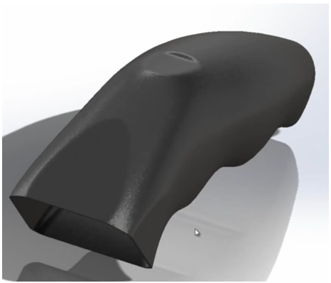
Dassault Systemes Solidworks 3d Model
We can apply Zebra Lines across the surface and analyse the quality of the model done with Inventor and I’ve taken the Inventor model, representing that of the Solidworks’ finished product so you can see what the surface quality looks like with most G1 fillets applied would look like under Zebra lines. It’s not an exact replica but it illustrates what happens to surface quality when you have G1 fillets applied to sharp edges.
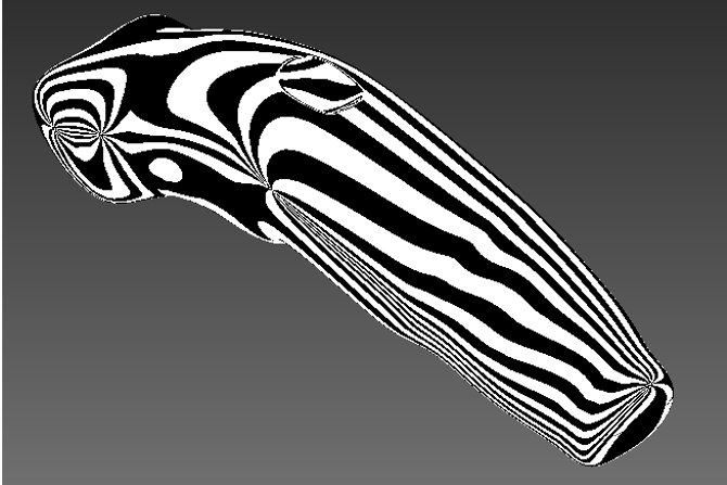
Autodesk Inventor 3D Model – Rear Iso Vew with Zebra Line Analysis
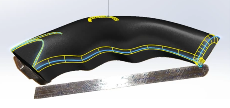
Dassault Systemes Solidworks 3D Model with G1 Fillets Highlighted
Applying Fillets to a surface, breaks the continuity of the surface. here’s what The Inventor model wouldl ook like if I applied extruded cuts with sharp edges and applied G1 fillets like the ones modelled in Solidworks:
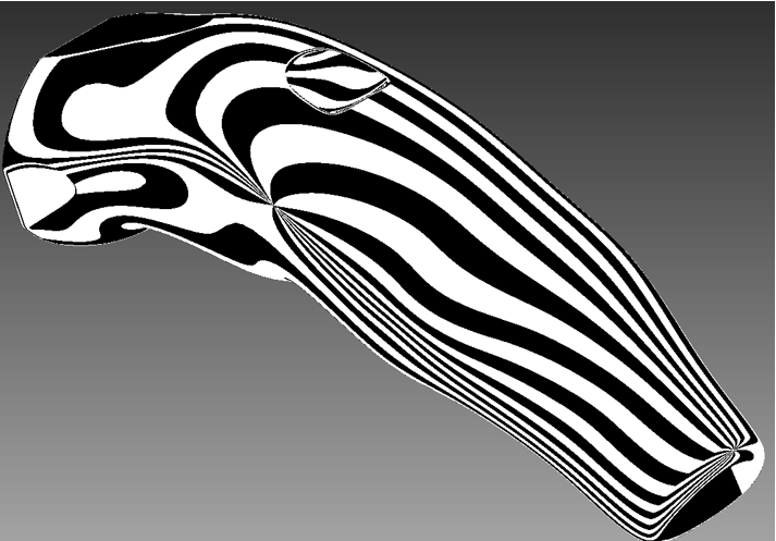
What Extruded Cuts with sharp edges and G1 fillets look like under Zebra Line Anlaysis.
As you can see under surface analysis, there are shaper line breaks compared to the Autodesk Inventor model which has smooth surface continuity along the model.
This picture to the left is the Inventor model with cuts and fillets. If I remodelled it exactly like the Soldiworks version, it would look much worse as the photo to the left doesn’t show all the surface breaks along the side and rear.
Summary Autodesk Inventor Vs. Dassault Solidworks
The reasons why Inventor’s surfacing tools can do it faster, more efficiently with better quality is because the focus is on the design not the tools. In Autodesk Inventor, you pick a plane, drop the surface in and start designing. With N.U.R.B.S. and T-Splines, the control and feedback you get from your design is amazing in comparison to Solidworks and much easier to learn, understand use and modify.
With Solidworks Surfacing tools, the focus is on knowing which tool to use, creating planes, 2D sketches, 3D sketches and knowing which surfacing command to use to execute a desired result, so the focus is more on the tools rather than on the design. Most CAD users have a decent workstation anyway, but, with twice as many items in the browser tree, a more complex part or assembly of parts decreases system performance.
On top of that, when making modifications to the design, the focus is back on knowing what tool did you use to create that part of the design and how do you modify it. Then after that, how it affects other features and fixing errors that arise when a one change causes a chain of events in the browser tree. This gets tricky when it’s a big change and requires editing of multiple features to achieve a simple outcome.
When doing the surfacing in Inventor, I could have started with a box surface and modelled it out, however, my interpretation from the shaver images was a rounded ergonomic design that contoured to the hand, rather than a squared type of surface with contours along the Y axis that cut in and out. The beauty of the surfacing tools inside Inventor is that If I wanted to change it from round to square, I can do so very easily by moving, adding or deleting edges.
In terms of surface quality, I’m positive that Solidworks can achieve a better result, but, I think it would take much much longer, or knowing a different design approach, by then, the Inventor user is already finishing the next project or task. Since creating the video, I’ve learnt a few more tricks, so I think If I re-modelled it, I could have shaved off another couple minutes too.
[polldaddy poll=8772218]

