The surfacing demo being benchmarked in CATIA is a 3D model of a watering can, modelled from scratch, so when I did it in Inventor, I took this on as a project where I would model up the initial design, and then go further and modify the surface and explore different design alternatives.
Here’s the video on how it was done in Autodesk Inventor:
[youtube https://www.youtube.com/watch?v=F9nU9v2_IKU&w=854&h=510]
Here’s the video on how it was done in Dassault Systemes CATIA V5:
[youtube https://www.youtube.com/watch?v=_1ckT-wz48g&w=854&h=510]
Here are the videos side by side:
Benchmark Results
After looking at the videos, the results are not surprising
Speed

The watering can was completed in Autodesk Inventor 47% quicker than doing it in Dassault Systemes CATIA V5. Around the 7 minute mark, when the Inventor model was completed, while the CATIA model was in the process of finishing of the spout off and had the handle and rest of the job still to do.
Browser Tree
The browser tree benchmark is where there is a big difference, with 70% less (planes, sketches and features) in the browser tree.

When it comes to control and feedback over your design, Inventor wins hands down. To be able to choose one feature and be able to modify it so easily and give direct feedback is a much better way of designing in my opinion over having to find the right plane, sketch or feature, go in and edit the one you want, then have to go into another and modify that one, etc., seems so much more painful, which is why I think many MCAD users don’t like to use surfacing tools.
Having said that, CATIA’s surfacing tools do have many surfacing tools with various options which is great for users to be able to pick and choose what they want when they choose a particular surface command.
Surface Quality
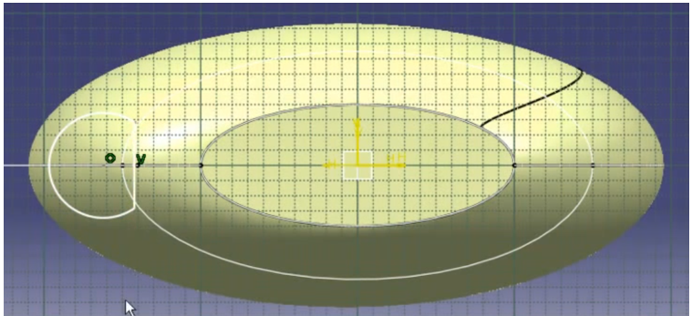
While the demo was pretty simple in terms of surface quality, three things stood out; Surface Control, Fillets and the Surfacing between the spout and the vessel, where the sketched circled needed to be trimmed with a line, so the spout wouldn’t overlap inside the vessel.
Surface Control
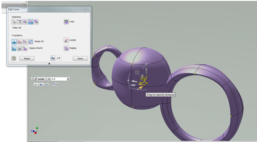
When you see the Surface Control in Inventor, especially after the design is done and I start playing around with control points, it’s obvious to see which has greater control and feedback. I am positive CATIA has some tools up its sleeve that Inventor could not do as easily too, but in this demo, nothing impressed me in CATIA.

Autodesk Inventor model in the Freeform Environment
CATIA has a reputation as being an advanced surface modeller, now, I don’t know if it’s because of all the surfacing options it has, or that because the add-on ICEM Surf is used in Automotive for surfacing and there’s confusion between the normal surfacing tools in CATIA or if people have never seen T-Splines in action.
Fillets
The fillets in the CATIA demo failed at 5mm and were adjusted to 10mm to make them work and they were only G1 fillets.

Dassualt Systemes CATIA model creating 5mm surface fillets

Dassualt Systemes CATIA model with 10mm G1 fillets
On top of that, it’s not the greatest fillet either with inconsistent continuity:

Dassault Systemes CATIA surface fillet quality
Autodesk Inventor could do fillets across all edges of 1mm and greater with G2 contiuity, which provides better surface continuity.

Autodesk Inventor model with 1mm G2 fillets

Autodesk Inventor model with Zebra line analysis of 1mm G2 fillets
Under Zebra Analysis, below is what 1mm G2 fillets look like compared to 10mm G1 fillets. You will notice more pronounced line breaks, resulting in a loss of continuity. That’s not taking into account the CATIA spout being modelled with sharp edges and inconsistent fillets either.

Autodesk Inventor model with 1mm G2 fillets on the left compared to 10mm G1 fillets on the right
The spout
The spout in the CATIA demo was created by sketching a circle, putting a line through it and trimming the circle across the line.

Dassault Systemes CATIA spout sketch
When the surface is extruded, it creates a sharp edge. This is what the edge in the CATIA model would look like under surface analysis:

Representation of Dassault Systemes CATIA model under zebra analysis
Now, this could be intentional for character styling for it’s really up to the designer. It’s debatable, but to me it looks more like a modeling limitation than creative styling.
Summary
I really liked what CATIA has to offer in terms of surfacing capabilities, however, a common thread seems to appear amongst MCAD surfacing tools and that is, you need to really know you’re CAD system, to produce quality surfaces, which is why many MCAD users shy away from Surfacing, because it’s not as user-friendly as solid-modeling.
You can take my views as bias, but look at the videos and the stats, Inventor was a pretty clear winner in my opinion. Inventor’s Freeform Surfacing tools are far easier to learn, easier to use, had less in the browser tree, provide better feedback when making modifications and produced a better quality surface, then on top of that CATIA is a much more expensive product. From my understanding you can buy an add-on in CATIA called Imagine and Shape module which is similar to the freeform tools in Inventor, but I have heard that it costs over $20k on top of CATIA. For an extra $20k with Autodesk you can buy Alias Surface and get some really amazing Class-A surfacing tools.
[polldaddy poll=8772218]

