1800 490 514 [email protected]

Autodesk Plant 3D vs Inventor: A Comprehensive Overview of DWG Workflows and Differences
autodesk inventor vs advance steel

Autodesk Plant 3D vs Inventor: A Comprehensive Overview of DWG Workflows and Differences

Autodesk Plant 3D vs Inventor

When it comes to CAD software, Autodesk offers a range of powerful tools tailored to specific industries. Two of the most popular among these are Autodesk Inventor and Plant 3D. Understanding the differences between these applications and their respective workflows is essential for professionals aiming to maximise their design efficiency.

This post provides a detailed comparison of Autodesk Inventor and Plant 3D, including a table that highlights their key differences, along with an in-depth analysis of their functionalities, workflows, and interoperability with other Autodesk tools.

Overview of Each Software

  • Inventor: Optimised for Small-Scale Mechanical Systems

Autodesk Inventor is ideal for projects involving detailed mechanical parts, assemblies, and compact systems. Its parametric 3D modelling capabilities allow engineers to create precise mechanical designs with intricate detail. The software’s tube and piping module is specifically designed for smaller piping projects, such as systems that can fit on the back of a truck.

However, while Inventor excels at mechanical design, it lacks built-in tools for process-specific tasks like P&ID creation. For projects that involve piping and instrumentation diagrams, users must create P&IDs manually, which can slow down the design process for larger, more complex systems.

  • Plant 3D: Designed for Large-Scale Process Plants

Autodesk Plant 3D is built for large, interconnected systems, particularly in industries like oil and gas, chemical processing, and water treatment. With its integrated AutoCAD P&ID tool, Plant 3D allows users to create P&IDs directly within the software. These P&IDs can be linked to 3D models, ensuring that any changes are reflected across the entire design, making the process more efficient and reducing the risk of errors.

Plant 3D also excels in plant-wide piping systems and isometric drawing generation essential for large-scale projects involving extensive piping runs and standardised equipment.

Key Differences Between Inventor and Plant 3D

The following table summarises the primary differences between Autodesk Inventor and Plant 3D:

FeatureAutodesk InventorAutodesk Plant 3D
Project SizeSmall mechanical systemsLarge plants, long pipe runs, extensive equipment layouts
Piping SystemsTube and Piping module for small-scale designsComprehensive plant-wide piping systems
P&ID IntegrationP&IDs must be created manuallyAutoCAD P&ID integrated, linked to 3D models
3D Equipment ModellingMechanical parts and compact assembliesPlant-scale equipment and piping systems
InteroperabilityExport 3D equipment to DWG, integrate with VaultSeamless catalogue management, isometrics generation
Collaboration ToolsAutodesk Vault for version controlIntegrated project management and collaboration tools
Isometric DrawingsNot natively supportedAutomatic generation from 3D models
Material ManagementFocused on mechanical parts and assembliesBOM for piping and equipment management
User InterfaceAdvanced 3D modelling environmentIntuitive interface for process design

DWG Workflows in Inventor and Plant 3D

DWG Workflows in Inventor:
  • File Creation: Users create 3D models in Inventor, which can be saved as DWG files for further editing in AutoCAD or for sharing with other stakeholders. This interoperability ensures that designs can be easily communicated and modified.
  • 2D Drawings: Inventor allows users to generate detailed 2D drawings from 3D models, ensuring that all views, dimensions, and annotations are accurately represented in DWG format. This feature is crucial for manufacturing processes where precise specifications are required.
  • Collaboration: The ability to export DWG files promotes collaboration with professionals who may not have access to Inventor but work within AutoCAD. This flexibility allows teams to work more efficiently, leveraging the strengths of each software.
DWG Workflows in Plant 3D:
  • P&ID Development: Plant 3D users can create P&IDs, which are saved as DWG files, serving as the blueprint for piping and instrumentation layouts. This foundational step is essential for any plant design project, as it establishes the functional layout of systems.
  • 3D Model Generation: The software allows users to create 3D models of piping systems and equipment that can be directly generated in DWG format. This feature streamlines the process of documentation and sharing, ensuring that all team members have access to the most up-to-date designs.
  • Isometric Drawings: Plant 3D supports the automatic generation of isometric drawings from 3D models, which are essential for piping layouts. This capability not only saves time but also reduces errors that can occur when manually creating these drawings.

Interoperability With Advance Steel and AutoCAD

Both Autodesk Plant 3D and Inventor offer interoperability with Advance Steel and AutoCAD, enhancing their usability across different engineering disciplines.

  • Advance Steel: While primarily for structural detailing, Advance Steel can take advantage of models created in Inventor and layouts from Plant 3D. This interoperability is beneficial for projects that require mechanical and structural components, enabling seamless integration of designs.
  • AutoCAD: As the foundational software, AutoCAD serves as a common platform for DWG files. Both Inventor and Plant 3D can export to and import from AutoCAD, allowing seamless collaboration across various teams. This interoperability ensures that design updates are easily shared and implemented, promoting efficiency in the overall workflow.

Integrating Inventor with Plant 3D: The Power of BIM

For projects that require mechanical equipment design and plant-wide piping systems, Autodesk provides a robust solution through BIM content publishing tools. With these tools, engineers can design 3D equipment in Inventor and seamlessly integrate that content into Plant 3D.

This integration is particularly valuable for professionals working on multidisciplinary projects. For example, custom-designed mechanical equipment created in Inventor can be published as BIM content and incorporated into the Plant 3D catalogue ensuring consistency and eliminating the need for rework between platforms.

Real-world Applications

Understanding the differences between Autodesk Plant 3D and Inventor also involves examining their applications in real-world scenarios.

  1. Manufacturing and product design: In industries such as automotive and aerospace, Autodesk Inventor is widely used to design mechanical components. Engineers leverage their parametric modelling capabilities to create complex assemblies, conduct simulations, and manage changes efficiently. The ability to export detailed 2D drawings in DWG format allows for effective communication with manufacturing teams.
  2. Process Plant Design: For industries like oil and gas, water treatment, and chemical processing, Autodesk Plant 3D is the go-to solution. The ability to create detailed P&IDs, generate 3D models of piping systems, and automatically produce isometric drawings streamlines the design process. Collaboration tools enable multidisciplinary teams to work cohesively, ensuring that every aspect of the plant design is accounted for.

Experience the Difference Between Autodesk Plant 3D and Inventor

Both Autodesk Inventor and Plant 3D are powerful tools, each designed for specific industries and applications. Inventor excels in mechanical design and manufacturing, while Plant 3D focuses on process and plant design. The choice between these two software options largely depends on the industry, project requirements, and desired workflows.

Understanding the differences in their DWG workflows, interoperability with other Autodesk products, and unique features is crucial for professionals aiming to enhance their design processes. By leveraging the strengths of each application, users can ensure that their designs are efficient, accurate, and tailored to their specific needs. Whether you are involved in mechanical design or plant engineering, choosing the right software is essential for success in today’s competitive landscape.

Get the best prices on Autodesk software.

Get skilled up and enroll in an Autodesk training course

Setup, libraries, programming and consulting services

Contact Us

Contact us to find out how we can help your business. Fill out the form below, by live chat, phone or email.

P: 1800 490 514 |  E: [email protected]

Connected Design

Design Consulting Autodesk Gold Partner
about design consulting Moving at the Speed of Business

VIEW MORE

Anisoprint Case Studies

Anisoprint kirsch kersch problem fiber steering composite 3D printing continuous fiber continuous fiber

Anisoprint Case Studies

Choose a case study below to learn more about the part material properties, print times and cost to print.

Wall Bracket

REINFORCEMENT SCHEME

2 COMPOSITE OUTER PERIMETERS, 40% COMPOSITE ISOGRID INFILL

PLASTIC

PETG

FIBER

COMPOSITE CARBON FIBER (CCF)

WEIGHT

25 G

PRINT TIME

6 HOURS

MATERIALS COST, PER CM³

~$0.68 AUD

MATERIALS COST, TOTAL

~$14.00 AUD

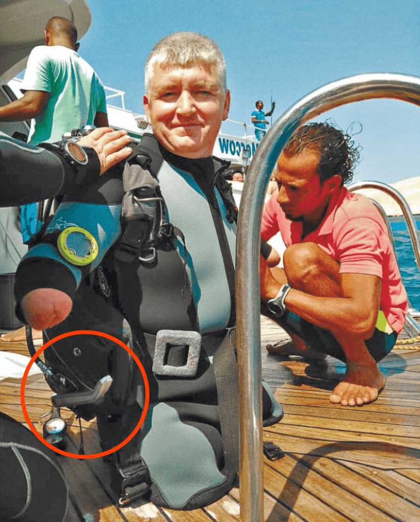
Level for Para-Athlete Driver

Para-athlete diver, Dimitry Pavlenko uses Anisoprint parts for an estimated 10x longer lifespan and superior strength.

Dmitry needed a lever to control air inflation and release for maintaining buoyancy and manoeuvrability. Usually, he used a spoon from steel as a lever. It was broken after the 10th dive.

He tried 3D printing and a new lever in ABS was printed, however, became defective also after the 10th dive and unusable.

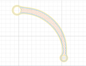
To increase the lifespan of the part, a new part was designed and printed on an Anisoprint Composer 3D printer from PETG and reinforced with Composite Carbon Fiber.

Anisoprint level para athlete 2 Moving at the Speed of Business
Anisoprint lever para athlete Moving at the Speed of Business
Anisoprint level para athlete 3 Moving at the Speed of Business

Using the Anisoprinted lever, Dimitry made a 40m deep, unassisted dive in open sea and set a new world record.

Anisoprint lever para athlete
Anisoprint level para athlete 5 Moving at the Speed of Business
Anisoprint level 8 aura Moving at the Speed of Business

REINFORCEMENT SCHEME

3 COMPOSITE OUTER PERIMETERS, 3 COMPOSITE INNER PERIMETERS

PLASTIC

PETG

FIBER

COMPOSITE CARBON FIBER (CCF)

WEIGHT

32 G

PRINT TIME

3.5 HOURS

MATERIALS COST, PER CM³

~$0.93 AUD

MATERIALS COST, TOTAL

~$21.00 AUD

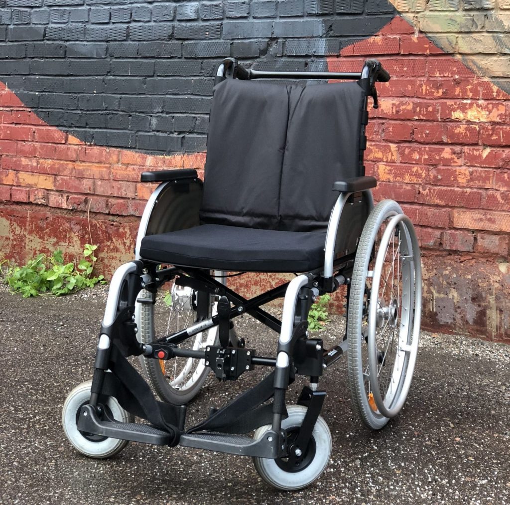
Electric Wheelchair Fixture

A fixture for an electric wheelchair was anisoprinted in-house 7x lighter, 12x faster and 3x cheaper than the original outsourced part from steel.

Supreme Motors produces UNA Wheel — an electric wheelchair for long distances. The original fixture was made from steel and was too expensive to manufacture it in small batches, with every unit costing over AUD$155.

The turned to 3D printing and found a high-performance plastic, Ultem. The part was 5x lighter, cheaper to make and the most importantly, the company could manufacture the fixtures in-house instead of outsourcing it and spending resources, however, the part 3D printed from Ultem failed stress tests and was not durable enough for application.

Supreme Motors looked for a stronger 3D printing solution and came across anisoprinting. The fixture was made from PETG plastic reinforced with Composite Carbon Fiber (CCF) was printed on an Anisoprint Composer continuous fiber 3D printer.

Anisoprint wheelchair fixture 2 Moving at the Speed of Business
Stress results, left to right: Anisoprinted, Ultem and Steel


Steel

Anisoprint (PETG + CONTINUOUS CARBON FIBRE)

Weight

300g

41g

Production time

48 hours

4 hours

Production stages

3

1

Price

AUD$150

AUD$40

Anisoprint fixture aura Moving at the Speed of Business

Under stress testing, the anisoprint withstood a dynamic load of 117kg, although being 7x lighter and 3x cheaper to produce than the traditional steel part. In addition to being able to print more durable parts, Supreme Motors can produce a part in 4 hours instead of 48 hours.

REINFORCEMENT SCHEME

3 COMPOSITE OUTER PERIMETERS, 3 COMPOSITE INNER PERIMETERS

PLASTIC

PETG

FIBER

COMPOSITE CARBON FIBER (CCF)

WEIGHT

41 G

PRINT TIME

4 HOURS

MATERIALS COST, PER CM³

~$1.27 AUD

MATERIALS COST, TOTAL

~$40.00 AUD

Anisoprint wheelchair fixture 3 Moving at the Speed of Business
Anisoprint wheelchair fixture 4 Moving at the Speed of Business

Self-Sensing Composite for Monitoring Critical Sructures

Brightlands Materials Center, a research center based in Netherlands, has developed 3D printed composite parts with self-sensing functionality using Anisoprint. Self-sensing provides the opportunity to monitor critical structures in aerospace, construction and healthcare industries.

What is Self-Sensing?

Self-sensing is the ability of a material to sense its own condition, whereby the material itself, is used as a sensor. Polymer-matrix composites, containing continuous carbon fiber, are known materials that have self-sensing capabilities based on measurable changes in electrical resistance of the continuous fibers. The practical importance of such products is in structural health monitoring in airplanes or critical parts in construction such as bridges.

Usually, self-sensing material is made with traditional composite manufacturing techniques that are complex and require several-stages and processes made with special equipment.

Brightlands Materials Center is combining the self-sensing of continuous fiber with the fabrication of composites by anisoprinting to make self-sensing more effective.

In their research, the results were discovered by monitoring deformation in a simple bending beam in a scale model of a pedestrian composite bridge.

For sensing it’s crucial to have full freedom that a carbon fiber layout gives because it has to stick out of the part to be able to make connections to the monitoring electronic hardware.

The Anisoprint open system gives the possibility of precise positioning and orientation of carbon fibers. The carbon fibers are placed at chosen locations inside the product that form an integral part of the structure. This means that the carbon fiber “sensors” are located where they are needed, and multiple fibers can form a range of sensors throughout the part.

Anisoprint self sensing 3 Moving at the Speed of Business
Anisoprint self sensing 5 Moving at the Speed of Business
Anisoprint self sensing 4 Moving at the Speed of Business

“As a materials research centre working on continuous fiber additive manufacturing we need flexibility with respect to the materials and fiber layouts that we can use on a 3D printer.

The Anisoprint Composers offer that flexibility enabling us to support our industrial customers to develop innovative fiber reinforced thermoplastic applications”.

– Richard Janssen, Business Developer of Brightlands Materials Center.

REINFORCEMENT SCHEME

2 COMPOSITE OUTER PERIMETERS

PLASTIC

PETG

FIBER

COMPOSITE CARBON FIBER (CCF)

PRINT TIME

35 HOURS

MATERIALS COST, PER CM³

~$1.10 AUD

MATERIALS COST, TOTAL

~$158.00 AUD

Anisoprint Filament Winding Machine Roller

REINFORCEMENT SCHEME

3 COMPOSITE OUTER PERIMETERS, 3 COMPOSITE INNER PERIMETERS

PLASTIC

PETG

FIBER

COMPOSITE CARBON FIBER (CCF)

WEIGHT

41 G

PRINT TIME

4 HOURS

MATERIALS COST, PER CM³

~$1.27 AUD

MATERIALS COST, TOTAL

~$40.00 AUD

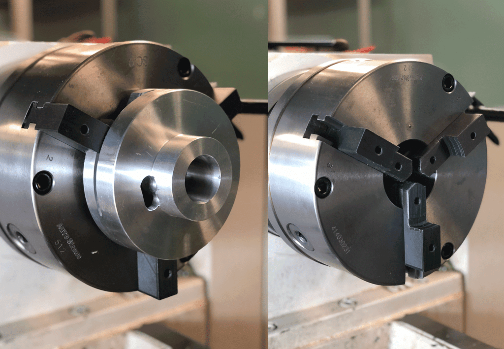
Continuous Carbon Fibre Reinforced Soft Jaws

Unique shapes with a 35% weight reduction and 40% lower manufacturing costs.

Operation on a lathe requires special attention to tooling. In cases when parts have complex shapes, thin walls, or are made of soft alloys, standard equipment can damage the surface and leave cracks on it.

Conventional tooling can crumple thin-walled parts because the clamping force is difficult to adjust. Parts such as asymmetrical profiles are very hard to clamp with standard jaws or cams: you either have to spoil and sharpen the cams or waste time and insert a row of liners, then centre the part in the machine.
To solve these problems, WEBER LABS turned to anisoprinting.

Anisoprint Soft Jaws Lathe

Weber Labs handles the full cycle of technological part production from model, development, calculations to manufacturing. Quite often these parts are small-scale and non-standard.

The soft-jaws produced need to have a specific purpose, in this case, turning a set of stator plates for an electric motor.

Anisoprint Soft Jaws Lathe 3 Moving at the Speed of Business

Weber Labs highlighted several advantages of Anisoprinted Tooling after testing:

  • Plastics jaws are more flexible than metal ones and when clamped, hold a workpiece more tightly, which helps control the clamping force more precisely and process parts that require careful handling.
  • On older machines, the placement of where the cams fit into wears out, and during operation, the tools leave noticeable traces on apart due to backlash and requires several finishing passes to clean up.
  • Due to its plasticity, soft jaws made from plastic provide better contact, not only minimises the number of finishing passes but also reduces vibration.


CNC METAL

ANISOPRINTING

Weight

600g

251g

Price

AUD$175.00

AUD$70.00

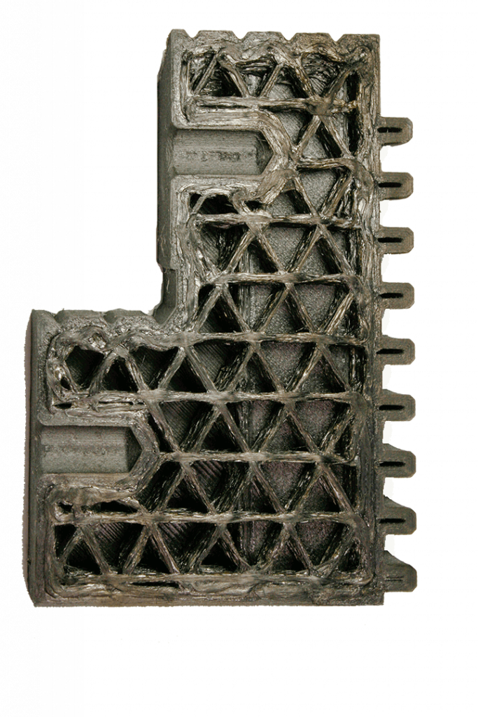
The composite jaws were printed on the Anisoprint Composer 3D printer from Smooth PA plastic reinforced with continuous fibers. Anisoprinted jaws are nearly three times as light as metal ones: 251g vs 600g.

The part is 40% cheaper and 35% lighter, than the metal equivalent. Such cams are less durable and cannot be used for holding large parts, however, this is non-standard tooling. Plastic jaws without reinforcement need to be changed after a few cycles of work, while reinforced 3D printed parts showed durability in more than 15 operation cycles.

Anisoprint Soft Jaws Lathe 4 Moving at the Speed of Business
Anisoprint Soft Jaws Lathe 5 Moving at the Speed of Business
Anisoprint Soft Jaws Lathe 6 Moving at the Speed of Business

Typically, production times for these cams is 29 hours. The outer plastic layer is 1.2mm thick, printed with SMOOTH PA, which is a carbon fiber filled plastic with excellent wear resistance.

REINFORCEMENT SCHEME

5 COMPOSITE OUTER PERIMETERS, 50% COMPOSITE ISOGRID INFILL

PLASTIC

SMOOTH PA

FIBER

COMPOSITE CARBON FIBER (CCF)

WEIGHT

251 G

PRINT TIME

29 HOURS

MATERIALS COST, PER CM³

~$1.55 AUD

MATERIALS COST, TOTAL

~$100.00 AUD

Composite Tool for Turbine Blade Production

8x weight reduction and 40% cost savings.

Shovel machines are used to convert mechanical motion into kinetic energy of a liquid or gas. They are used in impellers, turbines, turbopump units, fans, etc. It’s necessary to change the cross-section, thickness and inclination angle in different zones of the blade for higher efficiency. Metal stamps are traditionally used as tools for producing such blades since they have a complex shape. Different blade shapes require different stamps that in case of metal tools leads to a significant amount of cost and time..

Weight and cost of the tool can be dramatically reduced if it’s produced from composite materials using anisoprinting technology.

Anisoprint turbine blade tool 3 Moving at the Speed of Business

400 BAR PRESSURE

METAL

ANISOPRINTED COMPOSITE (Smooth PA + CBF)

SAVINGS

Weight

600g

251g

87%

Price

AUD$175.00

AUD$70.00

40%

Continuous fiber 3D printing decreases the tool’s weight 8xthat allows using cheaper equipment and operating it easier.

At the same time, there is a 40% cost reduction in comparison to the metal part withstanding the same strength.

Moreover, when printing tools on the Anisoprint Composer continuous composite 3D printer you know the exact date when you get the part without spending any time communicating with 3rd parties you outsource your machined parts to.

Anisoprint turbine blade tool 4 Moving at the Speed of Business


PLASTIC

SMOOTH PA

FIBER

COMPOSITE BASALT FIBER (CCF)

WEIGHT

3500 G

PRINT TIME

340 HOURS

MATERIALS COST, TOTAL

~$955.00 AUD

Composite Rocker for a Downhill Bike

40% reduction in manufacturing costs, 35% reduction in weight with smart load-orientated reinforcement.

Due to extremal operation conditions, downhill bikes should withstand significant loads, and one of the keys to this is a reliable suspension.

Anisoprint Downhill Bike Rocker 3 Moving at the Speed of Business
Downhill bike rocker made from metal using CNC

The rocker is an element in a suspension that obtains flexural loads while riding a bike. It’s often produced from metal by CNC technology (milling) that gives enough strength but is expensive. Continuous fiber 3D printing is a good opportunity to get the part of the same strength but reducing the cost and at th same time, the weight, which in sports, is always a good thing.

The composite rocker was printed on the Anisoprint Composer 3D printer from Smooth PA plastic reinforced with continuous fibers. The part withstands the same loads as metal one, however, is 40% cheaper to make and 35% lighter..

On this kind of bike, the components that could be also manufactured with anisoprinting are the front fork clamp and the pedal crank. Combining a 30% of weight reduction on each of these components, it’s possible to achieve at least a 1000g reduction, depending on the geometry of each part.

Anisoprint Downhill Bike Rocker 4 Moving at the Speed of Business


METAL

ANISOPRINTED COMPOSITE (SMOOTH PA + CBF)

Weight

500g

325g

Price

AUD$590.00

AUD$390.00

One of the most important advantages of anisoprinting is its capability to produce parts with the smart load-oriented reinforcement.

Anisoprint Downhill Bike Rocker 5 Moving at the Speed of Business

The rocker is reinforced in accordance with the expected loads using only the required amount of material. In contrast with milling, you get lots of waste that also has an impact on the overall manufacturing costs.

“One important aspect of using 3D printing in this business is to have the possibility to customize each frame on riders requirement.

It’s quite important because to be cost-competitive even if the frame is hand made, manufacturers need to keep some area of the CF frame standard and then adapt the frame on linear sections. In this way, bike manufacturers would have more flexibility in their bikes.”

— Filippo Pagnani, CEO of Prototipa Design, Italy

REINFORCEMENT SCHEME

10 COMPOSITE PERIMETERS, 80% COMPOSITE ISOGRID INFILL

PLASTIC

SMOOTH PA

FIBER

COMPOSITE CARBON FIBER (CCF)

WEIGHT

325 G

PRINT TIME

100 HOURS

MATERIALS COST, TOTAL

~$390.00 AUD

Clevis for Dairy Production Line

Production downtime reduced from 3 months to 6 hours. 3D Anisoprinted clevis has longer lifespan due to resistance to peroxide hydrogen.

A dairy brand company uses a clevis fixture at the production line. The clevis moves through, catches a yoghurt bottle and sends it to the washing area. The part is washed with peroxide hydrogen. The original part is made from milled polyamide, replacing a destroyed one takes 3 months due to ordering from a third-party. During this time, the production line fully stops: the company doesn’t get enough sales volume and suffers losses.

The part printed on Anisoprint Composer reduced production downtime from 3 months to 6 hours. It was made from PETG, which is resistant to peroxide plastic, and then reinforced with continuous carbon fiber by using anisoprinting technology. Due to the peroxide resistance, the lifespan of  the clevis’ increased.

Anisoprinting technology allows using any plastic as a matrix, so it’s possible to get composites with continuous fibers with the chemical properties you need for the application.

REINFORCEMENT SCHEME

3 COMPOSITE PERIMETERS

PLASTIC

PET G

FIBER

COMPOSITE CARBON FIBER (CCF)

WEIGHT

35.2 G

PRINT TIME

6 HOURS

MATERIALS COST, PER CC

~$1.12 AUD

MATERIALS COST, TOTAL

~$31.00 AUD

Legs for Mobile Robot used for Sensing, Inspection and Remote Operation

By Anisoprinting robotic legs, MSU were able to reduce weight by 70% and lower manufacturing costs by 40%.

In the Institute of Mechanics of MSU a mobile robot —  an analogue of BostonDynamics Spot was developed.

Autonomous operation requires energy which depends on the robot’s weight. Some of the components of the robot can be produced from composites with continuous fibers. It noticeably reduces the weight and allows robot to work longer without charge.

That’s the strategy the developers chose for their robot was to make it more functional.

For this robot as for any other innovative development, it’s very important to have flexibility in terms of design changes. Traditional manufacturing technologies can’t provide the freedom to change a prototype with many iterations without a significant time and money, however, with 3D printing, it can. 

With Anisoprint technology, you can easily set fiber laying paths and infill density in their special slicing software, Aura, to make the part more or less stronger according to results of the field tests.

With the possibility of changing prototypes anytime without spending a significant amount of time and money, the team reduced manufacturing costs by 40% in comparison to milling the part from Aluminium, which requires significantly more effort to redesign a part iteration.

To make the robot work longer, it’s necessary to reduce its weight as much as possible. Using anisoprinting it’s feasible to get the part of the same strength and stiffness characteristics but 70% lighter than the metal analogue.


ALUMINIUM

ANISOPRINTED COMPOSITE (SMOOTH PA + CCF)

SAVINGS

Weight

1225g

350g

70%

Price

AUD$715.00

AUD$400.00

40%

REINFORCEMENT SCHEME

3 OUTER COMPOSITE PERIMETERS, 3 INNER COMPOSITE PERMITERS, 50% COMPOSITE ISOGRID INFILL

PLASTIC

SMOOTH PA

FIBER

COMPOSITE CARBON FIBER (CCF)

WEIGHT

350 G

PRINT TIME

144 HOURS

MATERIALS COST, PER CC

~$3.42 AUD

MATERIALS COST, TOTAL

~$400.00 AUD

Parts with Holes (Kirsch Problem)

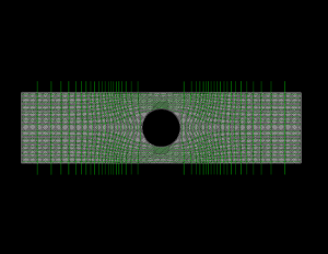
This experimental sample with a hole was reinforced without increasing its weight, while maintaining uniform stress distribution.

The fiber steering plate is an experimental demonstration of the method where anisoprinting an efficient reinforcement design of parts with the holes.

Holes are stress concentrators, significantly reducing the strength of structural elements. Traditionally, to increase the strength of an element, a part thickness is enhanced which leads to increasing the weight of the part.

Anisoprint kirsch problem 1 Moving at the Speed of Business

The part can be reinforced by using curvilinear trajectories that suit the load distribution and this type of reinforcement doesn’t require an increase in weight and only possible with a special approach to fiber laying from Anisoprint.


PLASTIC

PET G

FIBER

COMPOSITE CARBON FIBER (CCF)

WEIGHT

50 G

PRINT TIME

7 HOURS

MATERIALS COST, PER CC

~$0.62 AUD

MATERIALS COST, TOTAL

~$26.00 AUD

Aircraft Seat Support

An Airplanes lifetime cost was reduced through a 40% weight reduction of an anisoprinted aircraft seat support

Aircraft seat support bears 1.5 tons of load. The original part is made from aluminum and weighs 400g. We’ve anisoprinted a new part on Composer A4 3D printer with a 40% weight reduction.

With 100 such seat supports in an average single-aisle passenger plane, this weight reduction can add up to saving 25 kg per plane. In such fields as aerospace every kilo matters. Cost of fuel for every kilo in an airplane is $2000 a year and by just reducing the seat support, would save $50,000 a year, per plane.

REINFORCEMENT SCHEME

10 COMPOSITE PERIMETERS

PLASTIC

PETG

FIBER

COMPOSITE CARBON FIBER (CCF)

WEIGHT

250 G

PRINT TIME

40 HOURS

MATERIALS COST, PER CC

~$2.00 AUD

MATERIALS COST, TOTAL

~$412.00 AUD

Contact Us

If you would learn more about Anisoprinting, please contact us by calling on 1800 490 514, by filling out the form or clicking the live chat in the bottom right-hand corner.

VIEW MORE