It’s that time of year again to see what’s new in Autodesk’s Inventor 2017.Another pretty good release with new technology that are in line with where things are heading, a focus on cloud collaboration and enhancements that users have been requesting.

Below is a full list of what’s new, but here’s the top new things that I like and a short video of the Top Ten from Autodesk:
- AnyCAD: New STEP associativity and improvements to DWG associativity
- 3D sketching has been revamped
- Export to 3D pdf
- Improved mesh handling
- Shape Generator enhancements
- Share designs and design feeds within Inventor
- New presentation and exploded view features and enhancements
- Pattern enhancements
- Quantities based on design views and visibility
General – Enhancements and New Features
3D PDF
Autodesk Inventor now publishes 3D pdf files with the added option to attach files into the pdf
Inventor Connected Design
The new A360 connected design came out in Inventor 2016 R2 and the new 2017 release has significant performance and feature improvements and management tools:
- You could manage design share only on A360 drive, now there’s management tools to share designs inside Inventor.
- Move the positioning of teh Connected Design Entry button
- Design Share comments can sit inside Inventor
- Reporting on configuration issues
iFeatures – iFeatures can now modify multiple solid bodies in one operation

Guided Tutorials – You can create and publish your own Guided Tutorials

Content Centre – Libraries have been updated to the latest industry standards
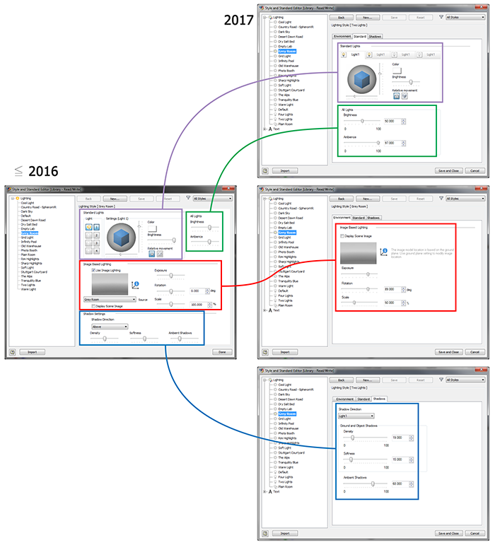
Lighting Styles Management – The Lighting Styles interface has been expanded into separate windows.

Shadow Settings – These settings are now individually managed based on each lighting style
New Keyboard Functions
These customisable options are now included:

Visual Conflict with Select Other – When you selected other in 2016 or earlier releases it would visually interfere with the area you were modifying, which has now been fixed.
Dialog Box Enhancements:
- Interference Dialog Box gets a new icon so you can zoom into the interference
- Customise Dialog Box – Ascending/Descending arrows have been added
- Parts List Dialog Box – Select one or more entries, right click and open the associated file
- BoM Dialog Box – Open a file from the drawing environment BoM Editor Dialog box
- iProperties Dialog Box – Sort iproperty values alphanumerically that are custom
- Resizeable Dialog Boxes:
- Interference Detected
- Insert iFeature
- Paste Features
- Custom tab in iproperties
- Custom dialog box in all tabs
Export to PDF – The system remembers when you modify a print range variable
Task Scheduler – Set defer update on Flat Patterns and Shrinkwrap Assemblies have been added
Recent Documents on My Home Tab – Set how many recent documents are displayed in memory
Graphics Display Enhancements – Luminence and brightness settings have been adjusted.

Graphics display enhancements
Parts – Enhancements and New Features
Patterns
- Circular Patterns – Set the orientation of the body or the feature set of the source, redefine the base point/feature set.
- Sketch Driven Pattern – New sketch driven pattern command to create patterns of features or bodies based on 2D/3D sketches. You can also redefine the base point or pick faces and re-orientate the pattern

Circluar pattern

Sketch driven pattern
Surfacing
- Boundary Patch – Guide rail is added so you can select curveshape the patch by electing points or curves.
- Ruled Surface – New angle option, Vector surface (aka Sweep) supports edge and sketch selections and you can alternate all faces or auto edge chain

Guide rails

Ruled surface

Boundary patch
Window Select Profiles – You can window select closed profiles when using the Extrude command
Parent Child relationship – Access the relationship through the model browser which include Sketches, Shared sketches, Axes, Planes and Points.

Parent child relationships
Part File Template – The template now has Master (locked), Isometric (default), Front, Top, Right view representations
Sheet Metal
Punch Representation Visibility – new controls to the representation display and flat pattern overrides to the Punch Tool dialog box such as show formed feature, sketch representation and centre mark
Corner Relief – Round (tangent), Round (vertex) and Square (Vertex) have been added

Compute Errors – Information icon has been added when there are computer errors and participates in the Design Doctor
Unfold iFeature – Some types of punch features can be unfolded
Sheet Metal Dialog Boxes – Apply button is now added to Corner Chamfer and Round and the Corner Round is resizable.
Defer Flat Pattern – You can defer the update on a flat pattern when opening a file or on a right click
Direct Edit Button – The Direct Edit button is added to the Sheet Metal ribbon instead of havingto go to the 3D model ribbon
Sketch
3D Sketching

The 3D sketch environment has been revamped making it easier to do 3D sketching with similar tools found in the Tube & Pipe routing module of Inventor.
New commands:
- Align to Plane
- Orient Z
- Orient to World
- Snap Intersection
New Controls:
- Ortho mode
- Dynamic dimension
- Snap object
- Infer constraints
Copy/Paste – You can copy/paste a 3D sketch entity in the same 3D sketch or between 3D sketches.
Drag Geometry – You can drag a 3D sketch by selecting any part of the sketch
New Constraints
- On Face
- Equal
- Parallel with X,Y or Z Axis
- Parallel to XY, YZ and XZ Planes

New 3D sketch constraints
Draw Curves on Face – By directly sketching it in place, you can create an interploated 3D spline on a parts face. The curve creation supports vertices, edges, constraints, point insertion, editing, curvature display and other options

Draw curves on face
3D Sketch Draw Tools
- Ortho mode, dynamic dimension and draw on plane
- 3D Transform

Assemblies
Make components transparent – Right click and select transparent or through iproperties > occurence

Cross-Part reference enhancements – additional controls and relationship details, open files from browser node

Tube & Pipe
- Find in browser – the context menu is enabled during a route and when placing flexible fittings
- Multi intermediate point creation – When modeling flexible hoses with fittings, you have two new options; offset point and intermediate point
- Show violations – message box displays when you check a bend radius with problems
- Dialog boxes – Styles, authoring, file names and field dialog boxes have been enhanced
- End treatment publishing – the last used end treatment setting populates when you add connections
- Change fitting diameter on flexible hose fittings is available
- When placing a fitting into an existing route there are new change size and edit connection options and a delete all option when selecting multiple tube and pipe components
- Spacebar flips fittings

Shape Generator
Shape Generator was added to Inventor 2016 R2 with the ability to assist in reducing weight in parts by producing a mesh based on your design and parameters to maximise the stiffness.

Preserve region
Inventor 2017’s Shape Generator allows you to:
- Target mass rather than a percentage reduction
- Preserve a region so when you run a study and the system gives you a mesh design, you can preserve a region not be meshed.
- Specify a minimum member size
- Symmetry

Minimum member size

Symmetry option
Presentations

New presentation interface
The Presentation section has been reworked to include Inventor Publisher features and existing IPN files can be migrated.
Presentation template – create a file based on a template or insert the model into an existing file.
Tweak components – tweaks can be saved as actions in an animation timeline
Add trail line – You can create trails from the tweak components mini toolbar
Component visibility and opacity – Right click to select visibility and to change opacity, select component > presentation tab > transform > opacity
Snapshot views – Create snapshots for animations in a timelilne and drawing views
Animations – Create an animation in a timeline by using snapshots or move/rotate component, change visibility/opacity and camera positions
Camera position – Update the camera view/position in a snapshot by editing the snapshot view
New publish options – publish video to AVI and WMV in HD or a raster image (BMP, GIF, JPEG, PNG & TIFF)
Drawings
- Jagged edges in section views
- Rectangular balloon style
- Drawing tables have automatic text wrapping in title and column headings
- Adjust QTY settings in Parts filter list

Jagged edges

Adjust quantity settings
Interoperability
AnyCAD
- Improved multi-threading – 2017 has had significant multi-threaded improvements when importing CATIA, Solidworks, NX and Pro-E/Creo files with more robustness when placed as a reference.
- Property overrides – Select property overrides or revert back to the values from the source file and the override vaules display in the BoM
- STEP Associativity
The AnyCAD functionality has extended to STEP files, so now if someone sends you a STEP file and modifies it, there is associativity and the changes will automatically update inside Inventor without having to re-import the file. This functionality not only works with STEP but 2D DWG, Autodesk Alias, Autodesk AutoCAD, Dassault Systemes Solidworks, Dassault Systemes CATIA V5 (I’m not aware of anything that is compatible to CATIA V6), PTC Creo, PTC Pro-Engineer and Siemens NX.
- 2D DWG Associativity Enhancements
With 2D DWG’s, the drawings in model space can be quite large and spanned in all sorts of directions within the coordinate system and can include borders, title blocks, attributes, dimensions and annotations. The new enhancements with DWG, allow the user to crop a section of the drawings and move that cropped section to a more manageable place in the Inventor environment (i.e. the origin 0,0,0).
The other enhancement is being able to place that dwg file in an Inventor part into an Inventor 2016 drawing as a view and maintain associativity between the dwg file and the Inventor drawing.
You can also add an instance of the same DWG in a part file.

Mesh Components
With more and more 3D printing and scanning, there have been significant improvements and new features when working with mesh files:
- Import/Export to OBJ – Great for 3ds Max interoperabilty
- Create faces from meshes
- Use constrain and assemble to create relationships between meshes and other mesh or part files
- Add work features such as workplanes, axes and points to meshes
- Measure distance and angle
- Load Express is now supported for meshes
- Visual styles are also supported for meshes

Translators
As mentioned under AnyCAD, you can insert a STEP file as a reference and maintain associativity.
Translators and supported file versions:


