Autodesk Advance Steel Training Fundamentals Course
Autodesk Advance Steel Training Fundamentals Course
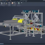
The Autodesk® Advance Steel software is a powerful 3D modelling application that streamlines the fabrication process through the use of a 3D model, which is used to create fabrication drawings, Bill of Materials (BOM) lists, and files for Numerical Control (NC) machines.
Since structural steel projects are extremely complex, the Autodesk Advance Steel software is also complex. The objective of the Autodesk® Advance Steel: Fundamentals training course is to enable you to create full 3D project models at a high level of detail and set them up in fabrication drawings.
This course focuses on the basic tools that the majority of users need. You begin by learning the user interface, basic 3D viewing tools, and the standard AutoCAD® tools that are routinely used.
Specific Autodesk Advance Steel objects, including structural columns, beams, bracing, plates, bolts, anchors, welds, and additional 3D objects are also covered. You will also learn about the powerful model verification tools. To complete the course, you will learn to edit and generate all of the required documentation files that enable your design to accurately and effectively communicate the final design.
- 16-Hours – 4 x 4-hour sessions
- Remote training over MS Teams
- Sessions are recorded and download links for each session are provide for future use
- Training for up to 1-3 People
- Sessions can start within 7 days upon ordering
- Flexible sessions (i.e. consecutive or Monday, Wednesday, Friday, etc.)
- Courses are private and topics can be customised to suit
- Includes Certificate of Completion
- Training manuals are additional $159 each for soft copy
Course Length: 16 Hours (4 x 4 Hour Sessions)
Topics Covered:
• Understand the process of 3D modelling and extracting 2D documentation from a model in the Autodesk Advance Steel software.
• Navigate the Autodesk Advance Steel interface.
• Work with 3D viewing tools.
• Review helpful AutoCAD tools.
• Work with the User Coordinate System (UCS).
• Use the Autodesk Advance Steel Modify commands.
• Add structural grids.
• Create levels.
• Model columns and beams and add bracing.
• Create connections using the Connection Vault.
• Create special parts.
• Verify models using Clash Checking tools.
• Modify a drawing prototype.
• Work within the Drawing Style Manager.
• Create custom connections.
• Create plates and add bolts, anchors, and welds.
• Add grating and cladding.
• Model ladders, stairs, and railings.
• Create concrete objects such as footings.
• Number objects.
• Extract 2D drawings from the model using Drawing Styles and Drawing Processes.
• Review and modify 2D drawings using the Document Manager.
• Modify 2D details with parametric dimensions.
• Revise models and drawings.
• Create BOM lists.
• Export data to .NC and .DXF files.
Contact Us
If you would to discuss Autodesk training courses, please contact us by calling on 1800 490 514, by filling out the form or clicking the live chat in the bottom right-hand corner.


