AutoCAD Vs AutoCAD Electrical
Many users who design electrical schematics and wiring diagrams use AutoCAD and AutoCAD LT as their tool of choice for 2D schematic and wiring design, however, Autodesk also has AutoCAD Electrical, a specialised product for electrical designers and engineers, available now with AutoCAD as a specialised toolset that can be downloaded and used if you have an AutoCAD Subscription.
What's the Difference?
AutoCAD Electrical has all the tools of AutoCAD plus specialised tools and catalog for electrical schematic design, reporting and panel layouts with integration with Autodesk Inventor which has electrical harnessing and nailboard drawing tools and BOM tables for wiring lengths and components.
In addition, Autodesk Vault Professional also has AutoCAD Electrical integration with additional options for working with electrical projects.
AutoCAD Electrical has these additional tools, not found if just using AutoCAD or AutoCAD LT:
- Project Tab
- SQL Database
- Schematic Components
- Circuits
- PLC
- Wire and Wire Numbers
- Terminals
- Catalog
- Panel Layout
- Reports
- Symbol Libraries
- Electromechanical Projects
- Integration for Vault Professional
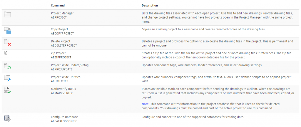
Project Tab
AutoCAD Electrical has a project manager tab, to manage all your electrical projects with tools to make projects active, customise, copy, delete and archive.
There are also buttons to refresh a drawing list, tasks list, update/retag and other file management tools.
Click here to learn more.
SQL Database
AutoCAD Electrical manages the catalog through a SQL database, giving users the ability to work with catalog database tables, with a detailed list of customisable Family Code/Table Names

Schematic Components
Using the schematic tools, an AutoCAD Electrical user can:
- Search for AutoCAD component
- Insert a component
- Insert at Fence Crossing Points
- Copy Data from One-line to Schematic
- Copy Component
- Copy Component at Fence Crossing Points
- Insert from User-Defined Pick List
- Insert from Equipment List
- Insert Components or Terminals from Panel Lists
- Cut, Copy, and Paste Electrical Objects
- Scoot Components/Wire Segments
- Align Components/Wire Numbers
- Stretch PLC Modules, Components, or Blocks
- Split PLC Modules/Components
- Reverse/Flip Components
- Swap Contact States
- Work With Cross-Referencing
- Surf on Cross-Reference Exception Reports
- Change Cross-Reference Visibility
- Insert a Location Box
- Retag Components
- Retrieve the Pinlist Values from a Peer Parent
- Check the Coil/Contact Count
Circuits
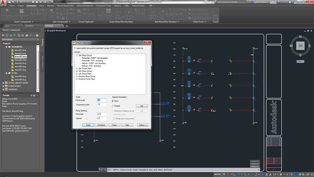
Circuits can be cut, copied and pasted and users can insert, configure single and dual circuits.
Using the circuit builder, the program builds dynamically and matches the rung spacing, adds wiring between components, and can annotate the circuit with calculated values based upon the assigned load amperage of the circuit. Circuit Builder extracts these annotation values from a database based on engineering standards, motor horsepower, and supply voltage.
PLC
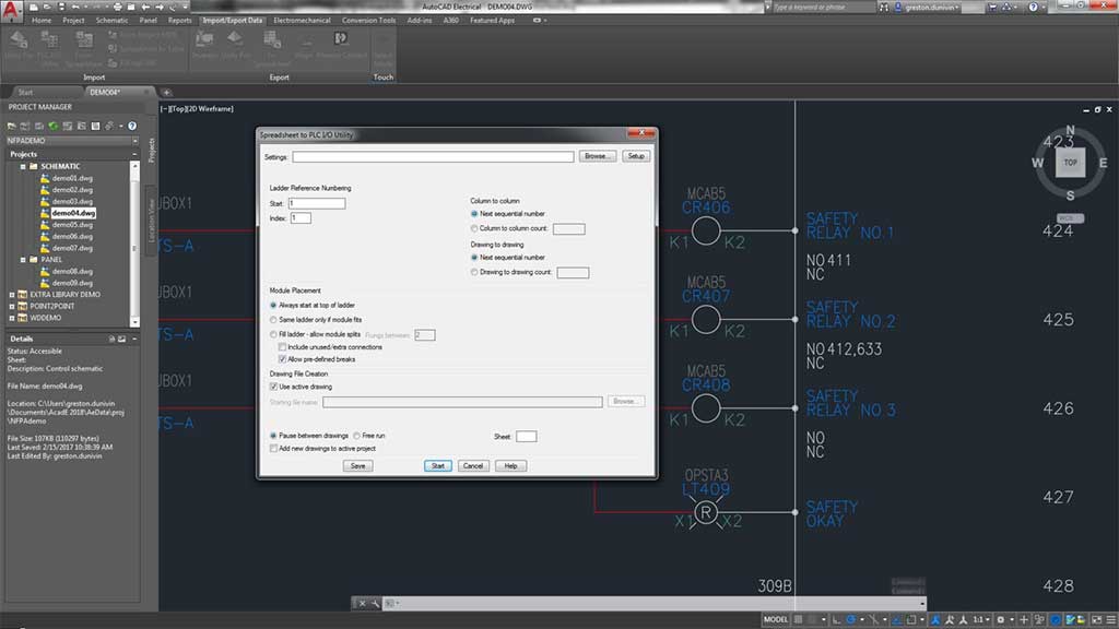
AutoCAD Electrical toolset can generate any number of different PLC I/O modules on demand and in various graphical styles. AutoCAD Electrical toolset generates the selected PLC I/O module through a parametric generation technique based on information in the PLC database (ACE_PLC.MDB).
Wires and Wire Numbers
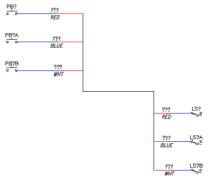
Create, import, select, and change wire types with AutoCAD Electrical using the schematic tab for:
- Different Wire Types
- Ladders
- Wire Gaps
- Single Arrows
- Tee MArkers
- Wire Sequence
- Internal Jumpers
- Wire Colour/Guage Labels
- In-Line Wire Labels
- Inserting Cable Markers
- Fan In/Out Source and Destination Markers
- Shield Symbols
- Inserting Wire Numbers
Terminals
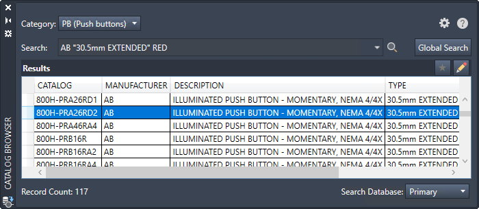
Terminals can be inserted from the Catalog browser and users of AutoCAD Electrical can define a Multi-Level Terminal by Catalog Value, by Terminal Block Properties, and associate Terminals on the same Drawing or across Drawings.
When selecting a terminal, the user can show terminal associations or break them apart.

Catalog
When working in the Catalog browser in AutoCAD Electrical, the user has a the ability to:
- Insert a Schematic Component From the Catalog
- Assign Catalog Information to a Component
- Predefine a Search Value for Catalog Browser Lookup Mode
- Copy Catalog Assignments
- Show Missing Catalog Assignments
- Update Components from the Catalog Database
- Work With Editing the Catalog Database Records
- Work With Catalog Database Tables
- Create a Project-Specific Catalog Database
- Define a Secondary Catalog Lookup File for a Project
- Move the Catalog Database File
- Edit or Add Manufacturer Content to the Catalog Database
- Search through the Catalog
Panel Layout
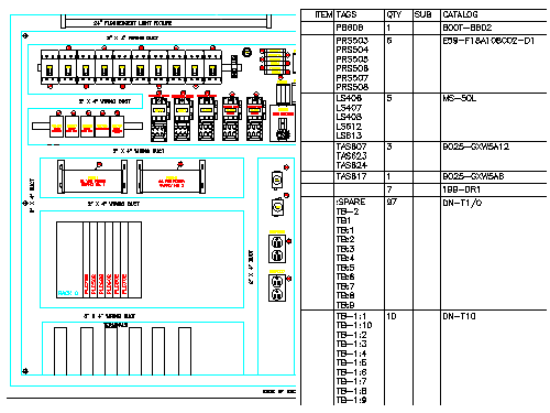
The Panel Layout tools create intelligent mechanical / panel layout drawings, whereby:
- Layouts can be driven from information carried on the AutoCAD Electrical toolset schematic wiring diagram drawings or they can be constructed independently of schematics.
- AutoCAD Electrical toolset places no requirements on special naming or attribute requirements on mechanical footprint symbols. Vendor-supplied footprint symbols, in AutoCAD format, can be used as is with AutoCAD Electrical toolset.
- Bi-directional update capabilities allow certain schematic wiring diagram edits to update the panel drawings automatically and vice versa.
- Wire number, wire color/gauge information, and connection sequencing data can be extracted directly from the schematics and annotated on to the panel footprint representations.
- AutoCAD Electrical toolset extracts various reports from these smart panel layout drawings including panel BOM, panel component/item lists, nameplate reports, and schematic versus panel exception reports.
Reports
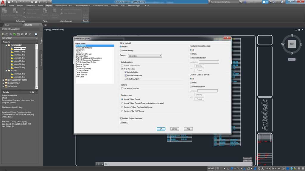
Users can generate reports based on the schematic design with the ability to:
- Generate a report
- Insert a report on to a drawing
- Change the format of a report
- Export the report to a spreadsheet
Symbol Libraries
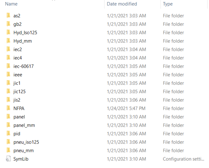
During a stand-alone installation of AutoCAD Electrical, all available symbol libraries are installed and users can remove any symbol libraries not required.
The symbol libraries and Symbol Builder template files are located at C:\Users\Public\Documents\Autodesk\Acade {version}\Libs. The symbol library subfolder, \Libs, carries various AutoCAD Electrical schematic and panel layout symbol libraries.
The following electrical schematic libraries are installed by default and multiple symbol libraries can be used within a project.
Electromechanical Projects
The Panel Layout tools create intelligent mechanical / panel layout drawings, whereby:
- Layouts can be driven from information carried on the AutoCAD Electrical toolset schematic wiring diagram drawings or they can be constructed independently of schematics.
- AutoCAD Electrical toolset places no requirements on special naming or attribute requirements on mechanical footprint symbols. Vendor-supplied footprint symbols, in AutoCAD format, can be used as is with AutoCAD Electrical toolset.
- Bi-directional update capabilities allow certain schematic wiring diagram edits to update the panel drawings automatically and vice versa.
- Wire number, wire color/gauge information, and connection sequencing data can be extracted directly from the schematics and annotated on to the panel footprint representations.
- AutoCAD Electrical toolset extracts various reports from these smart panel layout drawings including panel BOM, panel component/item lists, nameplate reports, and schematic versus panel exception reports.
Vault Professional Integration
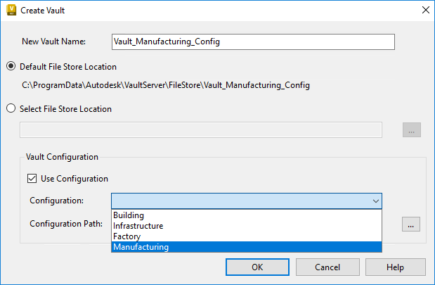
Vault Professional support AutoCAD Electrical .wdp project files where you can add and open an AutoCAD Electrical project to/from Vault using the .wdp file format and use the usual check in/out, revision/lifecycle and search features.
Autodesk Vault Professional allows you to:
- Keep a history of your design changes
- Review how your designs have progressed
- Rollback to a previous version
- Have a central shared secured repository of drawings and data
- Search for required information across multiple drawings and projects
What's new in AutoCAD Electrical 2023

Discover the Right CAD Tool for Your Engineering Needs
Choosing between AutoCAD and AutoCAD Mechanical? Our free eBook offers a detailed comparison to help you make the best choice for your design projects. Gain insights into key features, pricing, and real-world applications.
Download the eBook now to make an informed decision and optimise your workflow.
Get in Touch
DC is an authorised Autodesk Reseller providing products and services for the Architecture, Engineering, Construction, Infrastructure and Manufacturing Sectors.
Feel free to contact us on 1800 490 514, [email protected], by live chat or fill out the form below.
