Chat with us, powered by LiveChat

AutoCAD Map 3D: The Perfect Mapping Tool for Engineering and GIS Professionals

AutoCAD Map 3D is a powerful GIS software that allows CAD professionals to create, edit, and visualize geospatial data. It is a comprehensive toolset that includes everything you need to work with maps, 3D models, and other spatial data.
AutoCAD Map 3D GIS Mapping software

AutoCAD Map 3D: The Perfect Mapping Tool for Engineering and GIS Professionals

AutoCAD Map 3D is a powerful GIS software that allows CAD professionals to create, edit, and visualize geospatial data. It is a comprehensive toolset that includes everything you need to work with maps, 3D models, and other spatial data.

AutoCAD Map 3D is a geographic information system (GIS) software that is part of the AutoCAD family of products. It is designed for CAD professionals who need to work with geospatial data. AutoCAD Map 3D includes a comprehensive toolset for creating, editing, and visualizing maps, 3D models, and other spatial data.

Features and Benefits

AutoCAD Map 3D includes a wide range of features for working with geospatial data, including:

  • Data management tools for importing, exporting, and managing spatial data
  • 2D and 3D drafting tools for creating and editing maps and models
  • Visualisation tools for creating interactive maps and 3D models
  • Analysis tools for performing spatial analysis
  • Collaboration tools for sharing data and projects with others

There are many benefits to using AutoCAD Map 3D, including:

  • Increased productivity: AutoCAD Map 3D can help you save time and improve your workflow by providing a comprehensive toolset for working with geospatial data.
  • Improved accuracy: AutoCAD Map 3D can help you create more accurate maps and models by providing a variety of tools for data management, drafting, and visualisation.
  • Enhanced collaboration: AutoCAD Map 3D can help you collaborate with others more effectively by providing tools for sharing data and projects.
  • Increased flexibility: AutoCAD Map 3D is a flexible software that can be used for a variety of purposes, including engineering, construction, and environmental planning.

AutoCAD Map 3D Vs AutoCAD and AutoCAD LT

AutoCAD Map 3D is a more powerful and feature-rich version of AutoCAD than AutoCAD LT and AutoCAD. AutoCAD Map 3D includes all of the features of AutoCAD LT and AutoCAD, plus a number of additional features for working with geospatial data.

FeatureAutoCAD Map 3DAutoCAD LTAutoCAD
Data managementYesNoNo
2D and 3D draftingYesYesYes
VisualizationYesNoNo
AnalysisYesNoNo
CollaborationYesNoNo

The right version of AutoCAD for you depends on your specific needs. If you only need to:

  • Work with geospatial data, then AutoCAD Map 3D is the best choice.
  • Create basic 2D drawings, then AutoCAD LT is a good option.
  • Create basic 3D models or 2D drawings and don’t need any of the advanced features of AutoCAD Map 3D, then AutoCAD is the best choice.

Connecting AutoCAD Map 3D with other apps

AutoCAD Map 3D can be used with other Autodesk apps to create a more comprehensive and integrated workflow. For example, AutoCAD Map 3D can be used with AutoCAD Civil 3D to create 3D models of infrastructure projects. AutoCAD Map 3D can be used with Autodesk 3ds Max to create photorealistic renderings of maps and models.

AutoCAD Map 3D can be connected to a variety of GIS mapping data sources, including:

  • Shapefiles: Shapefiles are a common format for storing vector data. AutoCAD Map 3D can import and export shapefiles.
  • Geodatabases: Geodatabases are a powerful format for storing spatial data. AutoCAD Map 3D can connect to geodatabases hosted on a variety of platforms, including Microsoft SQL Server, Oracle, and IBM DB2.
  • Raster datasets: Raster datasets are a format for storing gridded data. AutoCAD Map 3D can import and export raster datasets.
  • Web services: Web services are a way to access spatial data over the internet. AutoCAD Map 3D can connect to web services that are hosted on a variety of platforms, including ArcGIS Online and Google Maps.

To connect AutoCAD Map 3D to a GIS mapping data source, you can use the following steps:

  1. Open AutoCAD Map 3D.
  2. Click the Map tab.
  3. In the Data Sources panel, click the Add button.
  4. Select the type of data source you want to connect to.
  5. Enter the connection information for the data source.
  6. Click the Connect button.

Once you have connected AutoCAD Map 3D to a GIS mapping data source, you can view and edit the data in AutoCAD Map 3D. You can also use AutoCAD Map 3D to perform spatial analysis on the data.

Here are some of the benefits of connecting AutoCAD Map 3D with GIS mapping data sources:

  • You can access a wider range of spatial data.
  • You can perform more complex spatial analysis.
  • You can share your work with others more easily.
  • You can collaborate with others more effectively.

If you need to work with geospatial data, then connecting AutoCAD Map 3D with GIS mapping data sources is a great way to improve your workflow and productivity.


Tailored Functionality

Organisations can customise AutoCAD for their industries, empowering teams to build and run discipline-specific routines and workflows.

Autodesk AutoCAD 2024 Specialised Toolset Moving at the Speed of Business

AutoCAD Map 3D 2024

Coordinate System Update

AutoCAD Map 3D 2024 supports the new coordinate systems in the following categories:

  • SnakeGrid EWR2
  • NAD83(CSRS) / Alberta 3TM

Refer to the 2024 Help file for further information 

Ready to get AutoCAD 2024?

Discover how Autodesk AutoCAD 2024 can streamline your workflow, increase productivity, and optimise your design process. 

Get up to 20% Off Software or Services!

Contact us to find out how much money you can save on software, training or other services. Fill out the form below, by live chat, phone or email.

P: 1800 490 514 |  E: info@designconsulting.com.au

Connected Design

Buy Autodesk AutoCAD 2024

AutoCAD 2024 Brochures

PDF Logo small Moving at the Speed of Business
AutoCAD 2024 Brochure
PDF Logo small Moving at the Speed of Business
AutoCAD LT 2024 Brochure
PDF Logo small Moving at the Speed of Business
AutoCAD vs AutoCAD LT 2024

VIEW MORE

AutoCAD Vs AutoCAD LT

AutoCAD vs Plant 3D: Which Software is Right For You?
AutoCAD vs AutoCAD LT Which product is right for you? Learn the differences between these two Autodesk products

Benefits of using AutoCAD vs. AutoCAD LT

AutoCAD® allows users to achieve a level of productivity for design creation that is not matched with AutoCAD LT®. 

Autodesk commissioned a study that explored the productivity and commercial differentiations between AutoCAD and AutoCAD LT when performing tasks ranging from creating geometry to creating plans and elevations, extracting object data, and applying and monitoring CAD standards.

Results showed that AutoCAD could allow a user to generate designs up to 3.9 times quicker* compared with AutoCAD LT, when these tasks were performed by an experienced AutoCAD user.

How AutoCAD Saves More Time Compared to AutoCAD LT

Parametric constraints – Time savings with AutoCAD up to 33%. AutoCAD offers complete geometric and dimensional constraint creation, editing, and management of parametric constraints.

Plans and elevations – Time savings with AutoCAD up to 46%. The 3D modeling tools in AutoCAD allow for easy manipulation to generate 2D plan and elevation objects.

Isometric drafting – Time savings with AutoCAD up to 61%. AutoCAD makes it easy to view 3D objects in isometric views and has visual styles that can be set to hide hidden detail.

Data extraction – Time savings with AutoCAD up to 90%. AutoCAD provides the functionality to extract data and create tables automatically, either in the drawing or in a Microsoft Excel® file.

CAD standards – Time savings with AutoCAD up to 81%. AutoCAD provides CAD standard functionality with a highly efficient method of checking standards against new and existing DWG files.

Text edting (Express Tools) – Time savings with AutoCAD up to 80%. AutoCAD includes Express Tools with advanced workflows when changing and manipulating text.

AutoLISP – Time savings with AutoCAD up to 50%. AutoLISP functionality is available in AutoCAD and AutoCAD LT. Direct access to AutoLISP editors only from AutoCAD
saves time when editing the application.

Markup Import and Markup Assist – Time savings with AutoCAD up to 71%. Using machine learning, AutoCAD can interpret handwritten annotation and suggest conversions to AutoCAD objects, saving time and reducing errors.

Smart Blocks: Placement and Replacement – Time savings with AutoCAD up to 40%.
The Smart Blocks: Replacement tool in AutoCAD provides a simple interface where multiple blocks can be selected and replaced by a chosen block in one operation.

Application programming interface (API) and
the app store – AutoCAD offers an API not available in AutoCAD LT that allows users to automate tedious and time-consuming tasks. AutoCAD users are also able to purchase and download apps in the Autodesk App Store and develop apps to benefit
AutoCAD users on your team.

Autodesk AutoCAD vs AutoCAD LT 2024 Highlights Video

Tailored Functionality

Organisations can customise AutoCAD for their industries, empowering teams to build and run discipline-specific routines and workflows.

Autodesk AutoCAD 2024 Specialised Toolset Moving at the Speed of Business
AutoLISP, a staple feature of AutoCAD desktop, now enables customizations to automate a sequence of commands in AutoCAD on the web 

AutoLISP

AutoCAD LT now includes AutoLISP

Leverage thousands of previously written programs created for use in AutoCAD-based programs. AutoCAD LT supports AutoLISP Source (LSP) files, compiled LSP files, Fast-load AutoLISP (FAS), and Visual LISP Applications (VLX) files.

Markup Import & Markup Assist

Faster cross-platform markup workflows through expanded machine learning capabilities & essential experience improvements 

Faster cross-platform markup workflows through expanded machine learning capabilities & essential experience improvements 

Markup Import Markup Assist​ Moving at the Speed of Business

AutoCAD 2024 Vs AutoCAD LT 2024

AutoCAD 2024 offers more advanced features for 3D modeling, customisation with add-on apps and APIs, rendering, and CAD standards, among other features, while AutoCAD LT 2024 is a more affordable version that still offers many of the essential features for 2D drafting, annotation, and automation. 

FeaturesAutoCAD 2024AutoCAD LT 2024
Find and replace blocks based on other blocks in your drawingYesNo
Stay informed of relevant file changes with details of multi-user activities in a DWG fileYesNo
Utilise AutoLISP programs to automate repetitive tasks and enhance workflowsYesYes
Extend AutoLISP programs with third-party automation libraries, and utilize specialised editors to write and debug programsYesNo
Create and edit 2D geometryYesYes
Annotate drawings with traces, text, dimensions, leaders & tablesYesYes
Customize the ribbon and tool palettesYesYes
Attach and import data from PDF filesYesYes
Share and use data from DGN files, Navisworks, & Bing MapsYesYes
Create and edit 3D models with solids, surfaces, & mesh objectsYesNo
Customize with add-on apps and APIsYesNo
Extract object data to tablesYesNo
Create renderings with lighting, materials, & visual stylesYesNo
Apply and monitor CAD standardsYesNo
Automate counting objects and blocksYesYes
Share drawings with colleagues directly from AutoCAD or AutoCAD LTYesYes
Import feedback and incorporate changes with a click of a buttonYesNo
Learn new features and workflows to work faster with My InsightsYesNo

What's New in Specialised Toolsets

AutoCAD Architecture and MEP 2024

AEC3DPRINT

With AEC3DPRINT command, you can natively export the AEC objects to an STL file format that’s compatible with 3D printing without converting to 3D solids.

Enhanced Design Center Content

New MVBlocks and block references are available in Design Center.

More than 200 new MVBlocks and block references are added to the AutoCAD Architecture (US Imperial) and AutoCAD Architecture (US Metric) content packs for Design Center. The added content is available in metric profile for non-English languages. The content includes external lighting, bathroom accessories, furniture, site, kitchen fittings, and more.

Enhanced Design Center Content Moving at the Speed of Business

Refer to the 2024 Help file for further information 

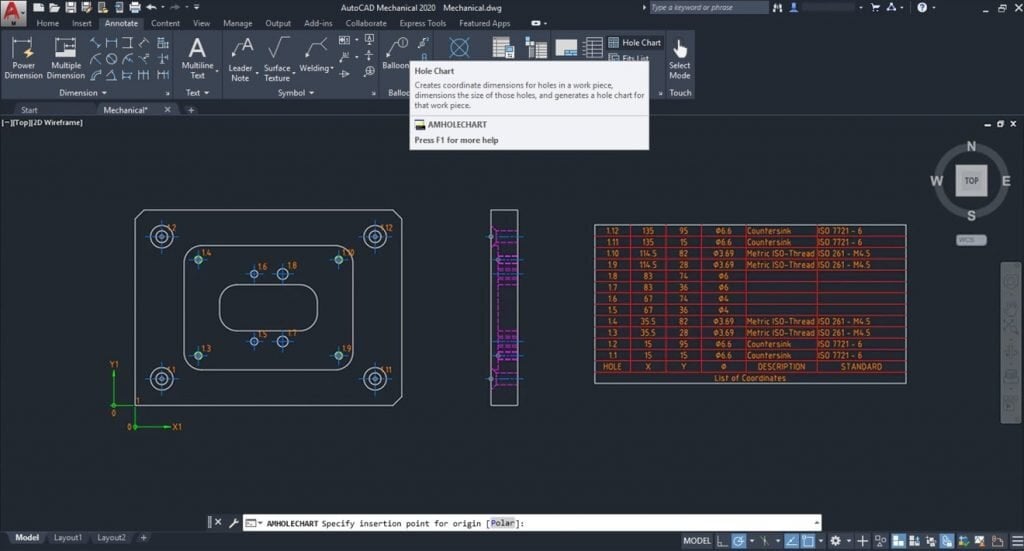
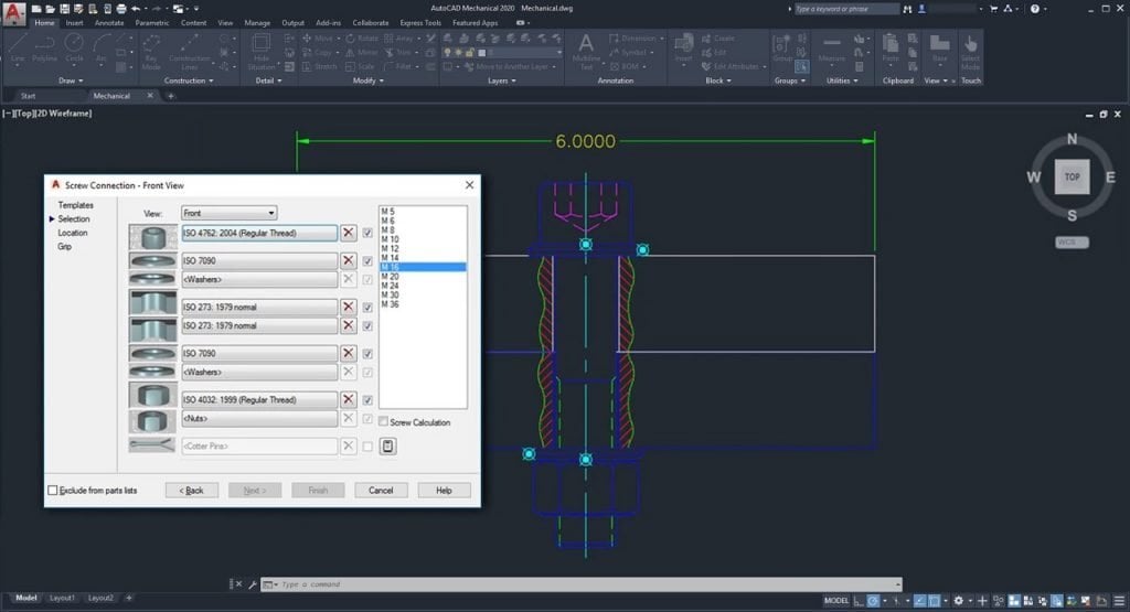
AutoCAD Mechanical 2024

ANSI/ASME Standard Revision Update

The section line symbol within AutoCAD Mechanical is updated to support the AWS Y14.3 – 2012 standard revision. To support AWS Y14.3 – 2012, all aspects of the section line symbol are revised to correspond with AWS Y14.3 – 2012.

AutoCAD Mechanical continues to support the AWS Y14.3 – 2003 standard revision to allow documents created in previous releases to be opened, edited, and saved without updating the section line symbol standard. By supporting AWS Y14.3 – 2012 and AWS Y14.3 – 2003, you can annotate new and as-built designs using the required standard revision.

ISO Standard Revision Update for Taper and Slope Symbols

The taper and slope symbol within AutoCAD Mechanical is updated to support the ISO 3040:2016(E) standard revision. To support the ISO 3040:2016(E), all aspects of the taper and slope symbol is revised to correspond with ISO 3040:2016(E).

AutoCAD Mechanical continues to support the ISO 3040:2009(E) standard revision to allow documents created in previous releases to be opened, edited, and saved without updating the taper and slot symbol standard. By supporting ISO 3040:2016(E) and ISO 3040:2009(E), you can annotate new and as-built designs using the required standard revision.

Refer to the 2024 Help file for further information 

AutoCAD Plant 3D 2024

Ortho Bill of Materials (BOM)

The Ortho Table Setup dialog box includes simplified options and more table capabilities for orthographic drawings. You can now add the Bill of Materials (BOM) for piping, equipment, steel, as well as nozzle and spool lists into ortho drawings.

Spec and Catalog Editor Enhancements

The Edit Parts and Edit Properties functions are enhanced in both Spec and Catalog Editors.

Edit parts within a selected parts family for inclusion in a spec sheet or catalog.

The Edit Parts and Edit Properties functions are enhanced in both Spec and Catalog Editors. Edit parts within a selected parts family for inclusion in a spec sheet or catalog.

Refer to the 2024 Help file for further information 

Pipe Spec Viewer Enhancements

View all parts available for a specific size in the selected spec. Use the search box to look for specific components in the Pipe Spec Viewer.

Any changes to the size and spec lists are both updated in Pipe Spec Viewer and the Part Insertion panel on the ribbon.

Ortho Single-Line Piping Enhancements

In this release, ortho single-line piping offers more enhancements including a new interface for some piping criteria providing better control when you display piping in a single-line representation in orthographic drawings.

AutoCAD Map 3D 2024

Coordinate System Update

AutoCAD Map 3D 2024 supports the new coordinate systems in the following categories:

  • SnakeGrid EWR2
  • NAD83(CSRS) / Alberta 3TM

Refer to the 2024 Help file for further information 

AutoCAD Electrical 3D 2024

Pipe Spec Viewer Enhancements

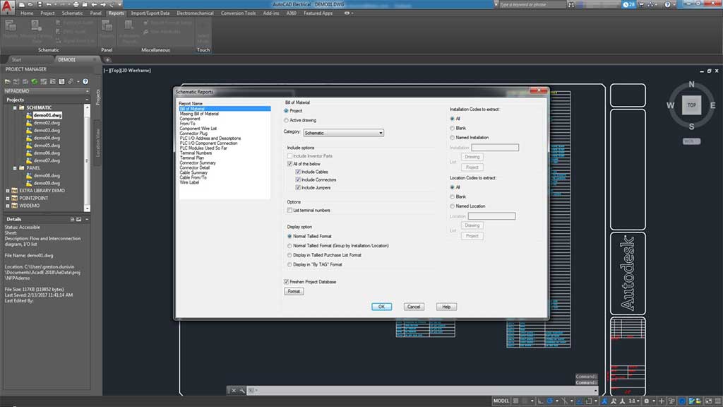
Create a schematic symbol table from schematic reports.

The schematic report lists the symbols used in the project along with its description in a table. You can also surf through a particular symbol that is used in various locations of the project.

Wire Type Synchronisation

Wire type can now be synchronized for all wires in the network with the same signal code across the drawings.

In previous releases, when you update the type of the wire connected to the source arrows, the destination wire type was not updated. In AutoCAD Electrical 2024 toolset, when the wire type is updated at the source arrow, all wires in the network are updated to the same wire type of the source. New wire layers are created along with its properties if the destination drawing doesn’t contain the new wire type.

Refer to the 2024 Help file for further information 

Ready to get AutoCAD 2024?

Discover how Autodesk AutoCAD 2024 can streamline your workflow, increase productivity, and optimise your design process. 

Get up to 20% Off Software or Services!

Contact us to find out how much money you can save on software, training or other services. Fill out the form below, by live chat, phone or email.

P: 1800 490 514 |  E: info@designconsulting.com.au

Connected Design

Buy Autodesk AutoCAD 2024

AutoCAD 2024 Brochures

PDF Logo small Moving at the Speed of Business
AutoCAD 2024 Brochure
PDF Logo small Moving at the Speed of Business
AutoCAD LT 2024 Brochure
PDF Logo small Moving at the Speed of Business
AutoCAD vs AutoCAD LT 2024

VIEW MORE

Whats New in Autodesk Vault 2024

Check out the latest in mechanical and product design and engineering in What's New in Autodesk Inventor Professional 2024
Check out what's new in the latest Autodesk Vault 2024 release

What's New in Autodesk Vault 2024

Autodesk Vault 2024 is out with a focus on enforcing standards, delivering intuitive tools and administrative enhancements

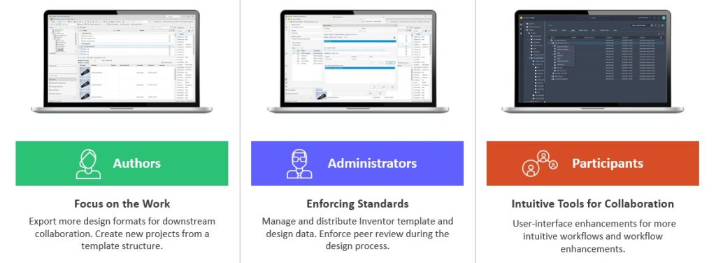
Autodesk Vault 2024 is out with a focus on enforcing standards, delivering intuitive tools and administrative enhancements. Focus on the Work Export more design formats for downstream collaboration. Create new projects from a template structure. Enforcing Standards Manage and distribute Inventor template and design data. Enforce peer review during the design process. Intuitive Tools for Collaboration User-interface enhancements for more intuitive workflows and workflow enhancements.

Authors: More features for CAD users in Vault 2024 to Focus on the Work

Job Processor: DXF and STEP

Users can export DXF and STEP files for manufacturing, suppliers, and subcontractors as part of the release process.

  • On-demand DXF/STEP publish
  • DXF/STEP publish on state transition
  • Sync LC state and revision on DXF/STEP files
  • DXF/STEP file getting created in vault to use Design Rep classification and PDF like workflow
  • DXF/STEP file publish options like PDF publish options

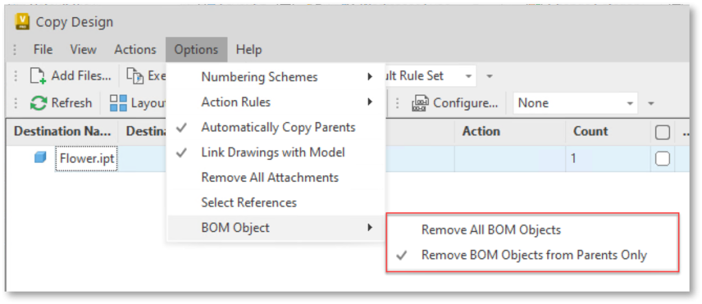
Copy Design Enhancements

Design re-use efficiency by reducing number of clicks to complete the workflow and pre-checks to prevent errors prior to creating a new design variation.

  • More usability by enabling Copy/Paste in the copy design numbering panel
  • Use the Copy/Paste functionality to edit multiple row values in and excel spreadsheet and then copy them to the Copy Design with one operation
  • More guidance through highlight restriction before copy operations start (property: –)
  • Export File list within the warning dialog

Copy Design BOM Enhancements

Newly copied parts can be assigned to an Item immediately after Copy Design is executed.

Copy Design updates the BOM information in part files without having to open them in Inventor first

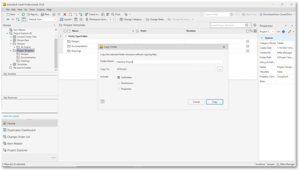
Copy Folder Structure

You can setup a new project quickly and start with a known folder structure.

  • Users can create a project folder from a template or previous folder structure
  • Copy Folder Structure permissions and Properties

Save up to 20% on Autodesk Vault Deployments

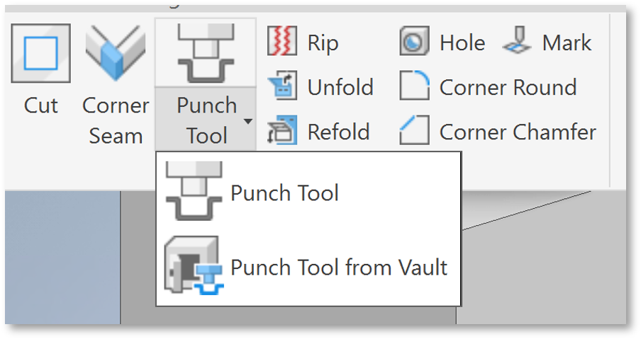
Insert Punch Tool from Vault

Users can select sheet metal punches from Vault when they are not in the local workspace.

Browse for 3D iFeature shapes from Vault to be inserted into the sheet metal face.

Administrators: Enforcing Vault Standards for Gratere Project Compliance

Inventor Design Data & Template Management

CAD Administrator can create and deploy template updates to users easily through Vault. Users remain up-to-date with templates and design data without manual updates.

The focus in 2024 is to create an Inventor\Vault integrated experience for the Template and Design Data Files with automatic updates of Templates and Design Data within specific workflows.

Peer Review

Control the lifecycle process by requiring a different user to transition to the next state. 

With this new user requirement, you can configure the Vault State transition to require Four Eyes Check and configure multiple rules for which files require Peer Review based on property values.

Job Processor

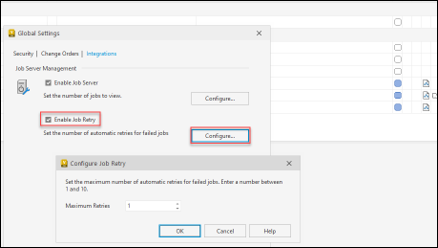
Apply retry strategy to visualization and custom jobs to reduce administration and user disruption to re-submit such jobs manually.

  • Automatic Retry capability for failed Job
  • Specify retry strategy between 1 and 10 attempts
  • The Job Processor will retry the failed jobs automatically without manual intervention

Thin Client Admin Settings

Administrators can set default columns for all Thin Client users in Autodesk Vault 2024.

Backup/Restore Enhancements

In Vault 2024, there is more flexibility in the Vault Server backup command to assist with backing up specified data components. This enhancement helps customers with large Vault environments that cannot use the existing backup command in the Vault Server.

Participants: Intuitive Vault Tools in 2024 for Project Collaboration

Thin Client – Enhancements

Select the Vault you need at the time of signing into the Thin Client and the Vault drop-down list shows the available Vault on the Server.

  • Improve interactions and control within the Thin Client interface with control for Expanding or Collapsing All for Objects with Structure.

Advanced Search capabilities paired with a modern UI for better experience:

  • Save searches as bookmarks in the browser
  • Search individual workspaces or multiple workspaces
  • Search workspaces of choice with search parameters
  • Search current folders and sub-folders
  • Find latest version only

Inventor Read-Only Vault Add-in

The Vault Add-in in Autodesk Vault Professional 2024 is available in Inventor Read-only, so users can open files and get access to Vault data directly from Inventor Read-only allowing users to review models efficiently without going between applications.

Learn More about Autodesk Vault 2024

Check out the Autodesk Vault 2024 Help

section for more information regarding the 2024 release.

Ready to get Autodesk Vault 2024?

Discover how Autodesk Vault 2024 can streamline your workflow, increase productivity, and optimise your design process. 

Vault is available from Design Consulting on-premise or cloud, so contact us to discuss which instance suits you best.

Get up to 20% Off Software or Services!

Contact us to find out how much money you can save on software, training or other services. Fill out the form below, by live chat, phone or email.

P: 1800 490 514 |  E: info@designconsulting.com.au

Connected Design

Check out what's new in the latest Autodesk Vault 2024 release

VIEW MORE

What’s New in Autodesk AutoCAD 2024

check out the latest ion AutoCAD 2024 with specialized toolsets. The essential software for industries such as manufacturing, engineering, construction, and infrastructure. Its industry-specific workflows, such as BIM and collaboration tools, help professionals to create accurate and efficient designs. Features like PDF import, DWG compare, data extraction, dynamic blocks, and layer management make AutoCAD a versatile and powerful tool for 2D drafting and 3D modeling.

What's New in Autodesk AutoCAD 2024

Autodesk AutoCAD 2024 is out with a focus on Accelerating Creativity, Tailored Functionality and a Connected Design Experience.

AutoCAD 2024 Categories Moving at the Speed of Business

Autodesk AutoCAD 2024 Overview

Accelerating Creativity

Focus on quickly creating and collaborating on innovative solutions using assistive machine learning technology to improve design workflows.

The performance enhancements in AutoCAD 2024 really stand out—both with how fast it opens and the speed of switching between models and view ports. It’s much faster than any previous versions.
Michael Shurgalla
Senior Design Technology Specialist, Merrick

Activity Insights

Bridge information gaps in collaborative AutoCAD workflows and stay connected to essential data throughout project lifecycles

My Insights Macro Advisor & Dashboard

Provides valuable information to you at the right time and in the right context to assist with steps that you can automate.

Count & Blocks Palette

Counting blocks is now up to 70% faster and reusing design content with blocks is up to 47% faster.

Autodesk AutoCAD 2024 Macro Advisor. Provides valuable information to you at the right time and in the right context to assist with steps that you can automate.
What's New in Autodesk AutoCAD 2024 - Automatically place blocks in your drawing based on where you’ve inserted the same ones thus far, reducing the number of clicks and saving you valuable time in the process.

Smart Blocks: Placement and Replacement

Automatically place blocks in your drawing based on where you’ve inserted the same ones thus far, reducing the number of clicks and saving you valuable time in the process.

Quickly find the blocks you need with machine learning powered functionality, delivering powerful time-saving automations.

Tailored Functionality

Organisations can customise AutoCAD for their industries, empowering teams to build and run discipline-specific routines and workflows.

Autodesk AutoCAD 2024 Specialised Toolset Moving at the Speed of Business

Ready to Get Connected?

Save up to 20% on Autodesk Software and Services

ACAD for Mac – M series chip

Added support for Apple Silicon increased AutoCAD for Mac’s overall performance by 2x*

Connected Design Experience

Autodesk creates an ecosystem of industry-leading design software and technology partners.

Web AutoLISP APIs

AutoLISP, a staple feature of AutoCAD desktop, now enables customisations to automate a sequence of commands in AutoCAD on the web 

AutoLISP, a staple feature of AutoCAD desktop, now enables customizations to automate a sequence of commands in AutoCAD on the web 

AutoLISP

AutoCAD LT now includes AutoLISP

Leverage thousands of previously written programs created for use in AutoCAD-based programs. AutoCAD LT supports AutoLISP Source (LSP) files, compiled LSP files, Fast-load AutoLISP (FAS), and Visual LISP Applications (VLX) files.

Markup Import & Markup Assist

Faster cross-platform markup workflows through expanded machine learning capabilities & essential experience improvements 

Markup Import & Markup Assist

Faster cross-platform markup workflows through expanded machine learning capabilities & essential experience improvements 

Markup Import Markup Assist​ Moving at the Speed of Business

Migrating Custom Settings

The CUI, tool palettes, and templates have undergone enhancements to facilitate the transfer of customised files and locations.

To utilise personalized configurations:

  1. Access the Autodesk AutoCAD <product and release> folder drop-down list from the Windows Start menu. Choose Migrate From a Previous Release.
  2. In the resulting Migrate Custom Settings dialog box, specify the release you wish to migrate from.
  3. Select the customized settings you want to transfer to the latest release.

Tab Improvements

The Start, File and Layout Tabs have been improved.

Trace Updates

Enhancements to the Trace environment continue, with the introduction of the COPYFROMTRACE command and additional settings controls on the toolbar.

Autodesk Docs Improvements

The following improvements have been made to Autodesk Docs:

  • Improved support and performance when viewing large files on Autodesk Docs.
  • Improved Desktop Connector resulting in improved performance displaying a drawing in the Start tab and opening a drawing from Autodesk Docs.
  • Improved navigation on the Start tab for drawings stored on Autodesk Docs

AutoCAD 2024 Vs AutoCAD LT 2024

AutoCAD 2024 offers more advanced features for 3D modeling, customisation with add-on apps and APIs, rendering, and CAD standards, among other features, while AutoCAD LT 2024 is a more affordable version that still offers many of the essential features for 2D drafting, annotation, and automation. 

FeaturesAutoCAD 2024AutoCAD LT 2024
Find and replace blocks based on other blocks in your drawingYesNo
Stay informed of relevant file changes with details of multi-user activities in a DWG fileYesNo
Utilise AutoLISP programs to automate repetitive tasks and enhance workflowsYesYes
Extend AutoLISP programs with third-party automation libraries, and utilize specialised editors to write and debug programsYesNo
Create and edit 2D geometryYesYes
Annotate drawings with traces, text, dimensions, leaders & tablesYesYes
Customize the ribbon and tool palettesYesYes
Attach and import data from PDF filesYesYes
Share and use data from DGN files, Navisworks, & Bing MapsYesYes
Create and edit 3D models with solids, surfaces, & mesh objectsYesNo
Customize with add-on apps and APIsYesNo
Extract object data to tablesYesNo
Create renderings with lighting, materials, & visual stylesYesNo
Apply and monitor CAD standardsYesNo
Automate counting objects and blocksYesYes
Share drawings with colleagues directly from AutoCAD or AutoCAD LTYesYes
Import feedback and incorporate changes with a click of a buttonYesNo
Learn new features and workflows to work faster with My InsightsYesNo

What's New in Specialised Toolsets

AutoCAD Architecture and MEP 2024

AEC3DPRINT

With AEC3DPRINT command, you can natively export the AEC objects to an STL file format that’s compatible with 3D printing without converting to 3D solids.

Enhanced Design Center Content

New MVBlocks and block references are available in Design Center.

More than 200 new MVBlocks and block references are added to the AutoCAD Architecture (US Imperial) and AutoCAD Architecture (US Metric) content packs for Design Center. The added content is available in metric profile for non-English languages. The content includes external lighting, bathroom accessories, furniture, site, kitchen fittings, and more.

Enhanced Design Center Content Moving at the Speed of Business

Refer to the 2024 Help file for further information 

AutoCAD Mechanical 2024

ANSI/ASME Standard Revision Update

The section line symbol within AutoCAD Mechanical is updated to support the AWS Y14.3 – 2012 standard revision. To support AWS Y14.3 – 2012, all aspects of the section line symbol are revised to correspond with AWS Y14.3 – 2012.

AutoCAD Mechanical continues to support the AWS Y14.3 – 2003 standard revision to allow documents created in previous releases to be opened, edited, and saved without updating the section line symbol standard. By supporting AWS Y14.3 – 2012 and AWS Y14.3 – 2003, you can annotate new and as-built designs using the required standard revision.

ISO Standard Revision Update for Taper and Slope Symbols

The taper and slope symbol within AutoCAD Mechanical is updated to support the ISO 3040:2016(E) standard revision. To support the ISO 3040:2016(E), all aspects of the taper and slope symbol is revised to correspond with ISO 3040:2016(E).

AutoCAD Mechanical continues to support the ISO 3040:2009(E) standard revision to allow documents created in previous releases to be opened, edited, and saved without updating the taper and slot symbol standard. By supporting ISO 3040:2016(E) and ISO 3040:2009(E), you can annotate new and as-built designs using the required standard revision.

Refer to the 2024 Help file for further information 

AutoCAD Plant 3D 2024

Ortho Bill of Materials (BOM)

The Ortho Table Setup dialog box includes simplified options and more table capabilities for orthographic drawings. You can now add the Bill of Materials (BOM) for piping, equipment, steel, as well as nozzle and spool lists into ortho drawings.

Spec and Catalog Editor Enhancements

The Edit Parts and Edit Properties functions are enhanced in both Spec and Catalog Editors.

Edit parts within a selected parts family for inclusion in a spec sheet or catalog.

The Edit Parts and Edit Properties functions are enhanced in both Spec and Catalog Editors. Edit parts within a selected parts family for inclusion in a spec sheet or catalog.

Refer to the 2024 Help file for further information 

Pipe Spec Viewer Enhancements

View all parts available for a specific size in the selected spec. Use the search box to look for specific components in the Pipe Spec Viewer.

Any changes to the size and spec lists are both updated in Pipe Spec Viewer and the Part Insertion panel on the ribbon.

Ortho Single-Line Piping Enhancements

In this release, ortho single-line piping offers more enhancements including a new interface for some piping criteria providing better control when you display piping in a single-line representation in orthographic drawings.

AutoCAD Map 3D 2024

Coordinate System Update

AutoCAD Map 3D 2024 supports the new coordinate systems in the following categories:

  • SnakeGrid EWR2
  • NAD83(CSRS) / Alberta 3TM

Refer to the 2024 Help file for further information 

AutoCAD Electrical 3D 2024

Pipe Spec Viewer Enhancements

Create a schematic symbol table from schematic reports.

The schematic report lists the symbols used in the project along with its description in a table. You can also surf through a particular symbol that is used in various locations of the project.

Wire Type Synchronisation

Wire type can now be synchronized for all wires in the network with the same signal code across the drawings.

In previous releases, when you update the type of the wire connected to the source arrows, the destination wire type was not updated. In AutoCAD Electrical 2024 toolset, when the wire type is updated at the source arrow, all wires in the network are updated to the same wire type of the source. New wire layers are created along with its properties if the destination drawing doesn’t contain the new wire type.

Refer to the 2024 Help file for further information 

Ready to get AutoCAD 2024?

Discover how Autodesk AutoCAD 2024 can streamline your workflow, increase productivity, and optimise your design process. 

Get up to 20% Off Software or Services!

Contact us to find out how much money you can save on software, training or other services. Fill out the form below, by live chat, phone or email.

P: 1800 490 514 |  E: info@designconsulting.com.au

Connected Design

Buy Autodesk AutoCAD 2024

AutoCAD 2024 Brochures

PDF Logo small Moving at the Speed of Business
AutoCAD 2024 Brochure
PDF Logo small Moving at the Speed of Business
AutoCAD LT 2024 Brochure
PDF Logo small Moving at the Speed of Business
AutoCAD vs AutoCAD LT 2024

VIEW MORE

Connected Design with the Autodesk Architecture Engineering and Construction Collection

The Autodesk Architecture, Engineering and Construction Collection streamlines design, analysis, and visualization for architecture, engineering, construction, infrastructure, and manufacturing industries. The suite of software programs improves efficiency, reduces errors and rework, and increases cost-effectiveness.
Design Consulting Architecture Engineering and Construction Collection logo Moving at the Speed of Business

Connected Design with the Autodesk Architecture Engineering and Construction Collection

In today’s fast-paced world, the construction industry is continuously evolving with new technology advancements. As technology advances, it becomes essential to have an efficient and connected design process that incorporates design, analysis, and visualization. The Autodesk Architecture, Engineering and Construction Collection is a comprehensive suite of software programs that facilitate this process. This blog post will discuss how the Autodesk Architecture, Engineering and Construction Collection can benefit various industries by connecting design, analysis, and visualization.

Connected Design Workflow: How Software Programs Work Together

The Autodesk Architecture, Engineering and Construction Collection consists of multiple software programs that allow for a connected design workflow. The software programs in the collection work together seamlessly, allowing for efficient design, analysis, and visualization. The collection includes software programs such as AutoCAD, Revit, Navisworks, and more. Each software program is designed to perform a specific task, and when used together, they create a comprehensive design workflow.

Designing with Precision: AutoCAD and Revit in the AEC Collection

The first step in any construction project is design. The Autodesk Architecture, Engineering and Construction Collection includes various software programs that aid in the design process. AutoCAD is a widely used software program that allows for 2D and 3D drafting. AutoCAD is used to create detailed drawings, and it is compatible with other software programs in the collection. Revit is another software program that is used in the design process. Revit allows for BIM (Building Information Modelling), which helps in creating a detailed 3D model of the building. By using Revit, the design process becomes more efficient, as the software program allows for collaboration between various stakeholders.

Revit and Civil 3D: Enhancing Infrastructure and Construction Projects with 3D Modeling and Efficient Design Collaboration

Revit and Civil 3D are commonly used in the AEC industry for infrastructure and construction projects. Revit creates 3D models of buildings, while Civil 3D designs infrastructure projects. Used together, they complement each other and improve the design process by identifying potential design issues in 3D models. Changes made in one software program are automatically updated in the other. This streamlines the design process and helps identify issues early in the design phase.

Ready to Get Connected?

Save up to 20% on Autodesk Software and Services

How Revit and Advance Steel Work Together to Streamline Steel Design and Fabrication

Revit and Advance Steel are two software programs that can be used together in the architecture, engineering, and construction (AEC) industry. Revit is a building information modeling (BIM) software that is used to create 3D models of buildings, while Advance Steel is a 3D modeling software that is used to design steel structures.

When used together, Revit and Advance Steel can improve the efficiency and accuracy of the design process. For example, an engineer can create a 3D model of a building in Revit and then export it to Advance Steel to design the steel structure. The engineer can then import the steel structure design back into Revit to ensure that it is compatible with the rest of the building design.

In addition, when changes are made in one software program, they are automatically updated in the other software program. This means that any changes made to the steel structure design in Advance Steel will be automatically reflected in the building design in Revit, and vice versa.

Using Revit and Advance Steel together can also help identify potential design issues early in the design phase. The 3D models created in Revit and Advance Steel can be used to identify clashes or conflicts that may have been missed in 2D design drawings. This can help save time and reduce the risk of errors and rework later in the project.

In conclusion, Revit and Advance Steel are powerful software programs that can be used together to improve the efficiency and accuracy of the design process in the AEC industry. The ability to export and import design elements between the two software programs and ensure that changes are automatically updated can streamline the design process and help identify potential issues early in the design phase.

Efficient Analysis with Navisworks and Autodesk Robot Structural Analysis Professional

The Autodesk Architecture, Engineering and Construction Collection includes software programs that aid in the analysis process. Navisworks is a software program that allows for coordination and simulation of construction projects. Navisworks helps in identifying clashes, reducing errors and rework, and creating more efficient designs. Additionally, Autodesk Robot Structural Analysis Professional is used to perform structural analysis of buildings. The software program helps in identifying structural deficiencies and optimizes the design process.

Bringing GIS Mapping and Connected Design Together: A Comprehensive Approach with Autodesk's AEC Collection

In today’s world, design and construction projects require a more comprehensive approach than ever before. With the Architecture Engineering and Construction (AEC) Collection from Autodesk, architects, engineers, and construction professionals have access to a suite of powerful tools that can help them collaborate and work more efficiently. One of the most valuable features of the AEC Collection is its ability to integrate with Geographic Information Systems (GIS) mapping, providing a more accurate and detailed view of project sites and landscapes.

AutoCAD Map 3D is a powerful software tool for GIS mapping, which allows users to access, manage and analyse spatial data. With AutoCAD Map 3D, users can easily import and export data from various sources, such as aerial imagery, satellite imagery, and other GIS data. This software also provides a wide range of tools for data analysis, visualization and editing, making it an essential tool for GIS professionals. Some of the key features of AutoCAD Map 3D include 3D modelling and visualisation, data query and analysis, and advanced geospatial analysis tools. By leveraging these features, users can create accurate and comprehensive maps and spatial data sets for a wide range of applications.

GIS mapping is a critical component of many construction projects, particularly those that involve large-scale developments or infrastructure. By overlaying geographic data such as topography, hydrology, and geology onto a digital map, project teams can better understand the context of their projects and make more informed decisions. The AEC Collection’s integration with GIS mapping tools allows architects, engineers, and construction professionals to access this data within their design software, creating a more seamless and connected workflow.

With the AEC Collection, design professionals can also collaborate with each other in real-time using tools such as Navisworks and Docs. Navisworks allows teams to integrate and coordinate models from multiple disciplines, while Docs enables document management and sharing across teams. By using these tools in conjunction with GIS mapping, project teams can ensure that all stakeholders have access to the most up-to-date information, reducing errors and improving overall project efficiency.

Enhancing Oil and Gas Plant Design with the AEC Collection and Plant 3D

The Architecture Engineering and Construction (AEC) Collection is a powerful suite of software programs designed to facilitate connected design for the architecture industry. One of the key software programs in this collection is Plant 3D, which is specifically designed for oil and gas plant design.

Plant 3D is a comprehensive software program that enables users to design, model, and analyze piping and instrumentation diagrams (P&ID) for oil and gas plants. With its intuitive interface and advanced tools, Plant 3D allows users to create accurate and detailed 3D models of plant layouts, equipment, and piping systems.

One of the key advantages of using the AEC Collection and Plant 3D for oil and gas plant design is the ability to collaborate with other disciplines in the industry, such as civil engineering and structural design. By working together in a connected design environment, designers and engineers can ensure that all aspects of the plant design are integrated seamlessly, from the initial concept through to construction and operation.

In addition, the AEC Collection and Plant 3D offer a range of powerful tools for data management and analysis, enabling users to track and monitor plant performance, optimize plant layouts, and identify potential safety hazards or operational issues.

Some of the key features of Plant 3D include:

  • Intelligent P&ID design and management tools
  • Comprehensive 3D modeling capabilities
  • Advanced piping and instrumentation analysis tools
  • Integration with other AEC Collection software programs, such as Navisworks and Docs

By leveraging these features, designers and engineers in the oil and gas industry can streamline their design processes, improve collaboration, and ensure that their plant designs are optimized for safety, efficiency, and performance.

Enhancing Visualisation with 3DS Max and InfraWorks

Visualisation is an essential part of any construction project. The Autodesk Architecture, Engineering and Construction Collection includes software programs that aid in the visualization process. 3DS Max is a software program that allows for rendering and animation of 3D models. 3DS Max helps in creating realistic visuals, which help in selling designs to clients. Autodesk InfraWorks is another software program that helps in creating visualizations of infrastructure projects. InfraWorks allows for collaboration between various stakeholders, and it helps in creating a more efficient design process.

Streamlining AEC Projects with Autodesk Docs

Autodesk Docs is a powerful document management tool that can help streamline AEC projects when used in conjunction with the Architecture Engineering and Construction Collection (AEC Collection) software. The AEC Collection includes several software programs that are essential for building design and construction, including Revit, Civil 3D, and Advance Steel.

By using Autodesk Docs to manage project documents, stakeholders can easily access and collaborate on project files from anywhere, at any time. This can improve project efficiency and communication, as all team members can stay up-to-date on project progress and changes.

Moreover, the AEC Collection software can be seamlessly integrated with Autodesk Docs, allowing users to store and manage their project files directly within Autodesk Docs. This integration makes it easier for teams to collaborate on project files and ensures that all project documentation is stored in one place, reducing the risk of lost or missing files.

For example, Revit models can be directly linked to Autodesk Docs, allowing team members to access and collaborate on the most up-to-date model at all times. Civil 3D designs can also be stored in Autodesk Docs, making it easy to share and collaborate on complex civil engineering projects.

Overall, by using Autodesk Docs in conjunction with the AEC Collection software, AEC professionals can streamline their project workflows, improve collaboration and communication, and ensure that project documentation is secure and easily accessible.

AEC Collection in Various Industries: Architecture, Engineering, Construction, Infrastructure, and Manufacturing

The Autodesk Architecture, Engineering and Construction Collection is beneficial to various industries. Here are a few examples:

Architecture: The Autodesk Architecture, Engineering and Construction Collection is used by architects to design and visualise buildings. The software programmes in the collection allow for efficient design, analysis, and visualisation.

Engineering: Engineers use the Autodesk Architecture, Engineering and Construction Collection to perform structural analysis and design. The software programmes in the collection help in identifying structural deficiencies, optimising designs, and creating efficient designs.

Construction: The Autodesk Architecture, Engineering and Construction Collection is used in the construction industry to coordinate and simulate construction projects. The software programmes in the collection help in identifying clashes, reducing errors and rework, and creating more efficient designs.

Infrastructure: The Autodesk Architecture, Engineering and Construction Collection is used in the infrastructure industry to design and visualise infrastructure projects. The software programmes in the collection, such as InfraWorks, help in creating visualisations of infrastructure projects. InfraWorks allows for collaboration between various stakeholders, including engineers, designers, and contractors. By using the Autodesk Architecture, Engineering and Construction Collection, infrastructure projects can be completed more efficiently and cost-effectively.

Manufacturing: The Autodesk Architecture, Engineering and Construction Collection is also used in the manufacturing industry. The collection includes software programmes that aid in the design of manufacturing equipment and machinery. Autodesk Inventor, for example, is used to design and test products before they are manufactured, reducing errors and costs.

Architecture Engineering and Construction Collection Connected Design Matrix

SoftwareDescriptionFile TypeCommandImport/ExportLink
AutoCAD2D and 3D computer-aided design software used for creating blueprints, schematics, and modelsDWG, DXF, DWFDRAWING, MODEL, VIEW, PLOTImport: DWG, DXF, DWF, PDF, STEP, SAT, IGES, STLExport: DWG, DXF, DWF, PDF, STL, OBJ, FBX
RevitBuilding information modeling (BIM) software used for creating detailed 3D models of buildings and structuresRVT, RFA, RTEOPEN, VIEW, EXPORT, PRINTImport: DWG, DXF, IFC, SAT, SKP, 3DM, STL, OBJ, FBXExport: DWG, DXF, DWF, PDF, IFC, SAT, SKP, 3DM, STL, OBJ, FBX
Civil 3DCivil engineering design and documentation software used for designing, analyzing, and documenting civil engineering projectsDWGCIVIL3D, C3DImport: DWG, LandXML, RevitExport: DWG, LandXML, Revit
InfraWorksInfrastructure design and engineering software used for creating 3D models of infrastructure projectsIAMOPEN, MODEL, VIEW, EXPORT, PUBLISHImport: DWG, DGN, GIS, SHP, KML, FBXExport: DWG, DGN, FBX, COLLADA, OBJ, IFC, KMZ
3ds Max3D modeling, animation, and rendering software used for creating visualizations of buildings and environmentsMAXOPEN, MODEL, RENDERImport: DWG, FBX, DAE, OBJ, 3DS, STLExport: DWG, FBX, DAE, OBJ, 3DS, STL
NavisworksProject review software used for 3D coordination, model analysis, and clash detectionNWD, NWFOPEN, APPEND, EXPORT, PUBLISHImport: DWG, DWF, DGN, IFC, SKP, FBX, 3DS, OBJExport: DWF, DWFx, NWC, NWF, FBX, 3DS, OBJ
Advance SteelSteel detailing software used for creating structural steel models and fabrication drawingsDWG, DSTVOPEN, MODEL, EXPORTImport: DWG, CIS/2, SDNF, IFC, STEP, SAT, SKPExport: DWG, DSTV, CIS/2, SDNF, IFC, STEP, SAT, SKP
Robot Structural Analysis ProfessionalStructural analysis software used for simulating and analyzing building structuresRST, RSA  

AEC Collection: A Valuable Tool for Cost-Effective Design Processes.

In conclusion, the Autodesk Architecture, Engineering and Construction Collection is a comprehensive suite of software programs that facilitates a connected design workflow. The software programs in the collection work together seamlessly, allowing for efficient design, analysis, and visualization. By using the Autodesk Architecture, Engineering and Construction Collection, various industries can benefit from a more efficient and cost-effective design process. The collection is beneficial to architects, engineers, construction professionals, infrastructure designers, and manufacturers. The collection is continuously evolving to meet the needs of these industries, and it remains a valuable tool in the construction industry.

Ready to get your Design Connected?

Discover how Autodesk Architecture Engineering and Construction Collection can streamline your workflow, increase productivity, and optimise your design process. 

Get up to 20% Off Software or Services!

Contact us to find out how much money you can save on software, training or other services. Fill out the form below, by live chat, phone or email.

P: 1800 490 514 |  E: info@designconsulting.com.au

Connected Design

The Autodesk Architecture, Engineering and Construction Collection streamlines design, analysis, and visualization for architecture, engineering, construction, infrastructure, and manufacturing industries. The suite of software programs improves efficiency, reduces errors and rework, and increases cost-effectiveness.

Connected Design with Architecture Engineering and Construction Collection

Click a link below to learn more about Connected Design using the Autodesk Product Design & Manufacturing Collection 

VIEW MORE

Connected Factory Design with Autodesk Product Design & Manufacturing Collection

Connected Factory Design Moving at the Speed of Business
Design Consulting Product Design Manufacturing Collection Moving at the Speed of Business

Connected Factory Design with Autodesk Product Design & Manufacturing Collection

The Benefits of Connected Factory Design with Autodesk Product Design & Manufacturing Collection

In today’s competitive manufacturing landscape, it’s crucial for companies to design and build factories that are efficient, cost-effective, and adaptable to changing market demands. With the help of advanced technology, such as Autodesk’s Product Design & Manufacturing Collection, Autodesk Inventor, AutoCAD Architecture, and Navisworks, manufacturers can streamline their factory design process, reduce errors, and improve productivity.

In this blog post, we’ll explore the benefits of using Autodesk’s Product Design & Manufacturing Collection, Inventor, AutoCAD Architecture, and Navisworks using the Factory Design Utilities and how these tools are connected. We’ll also discuss real-world applications of connected factory design and how it can empower manufacturers to stay ahead of the competition.

Introduction to Connected Factory Design with Autodesk

Connected factory design refers to the use of advanced software tools to create a cohesive, streamlined design process for factories. This approach involves integrating various design and simulation tools to create a single, unified workflow. Autodesk’s Product Design & Manufacturing Collection is a powerful suite of software tools that allows manufacturers to create a connected factory design process.

Benefits of Using Product Design & Manufacturing Collection for Factory Design

The Product Design & Manufacturing Collection includes several powerful tools that can help manufacturers design and simulate their factories with greater efficiency and accuracy. Here are some of the key benefits of using these tools for factory design:

  1. Streamlined Design Process: Autodesk’s tools allow manufacturers to create a connected factory design process that integrates various design and simulation tools. This approach can help reduce errors and streamline the design process, resulting in faster time-to-market.

  2. 3D Modeling: With Autodesk Inventor, manufacturers can create 3D models of their factories, allowing them to visualize and optimize their designs before construction begins. This can help reduce costs and ensure that the factory meets all functional requirements.

  3. Building Design Optimization: AutoCAD Architecture provides a suite of powerful tools for building design optimization. This includes features such as automated documentation, advanced rendering, and collaboration tools, which can help manufacturers create optimized building designs.

  4. Factory Design and Simulation: Navisworks allows manufacturers to create detailed simulations of their factories, including machinery, equipment, and workflows. This can help identify potential issues before construction begins and ensure that the factory operates efficiently once it’s up and running.

factory design suite 2 Moving at the Speed of Business

Enhancing Factory Design with Navisworks and Factory Design Utilities

Navisworks and Factory Design Utilities are two key tools within the Product Design & Manufacturing Collection that can help manufacturers enhance their factory design process. Navisworks allows for detailed factory simulation, while Factory Design Utilities provides a suite of tools specifically designed for factory design.

Some of the key features of these tools include:

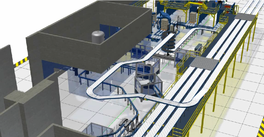
  1. Factory Design Utilities: This tool provides a suite of powerful tools specifically designed for factory design, including conveyor design, layout optimization, and factory equipment libraries.

  2. Navisworks: Navisworks allows manufacturers to create detailed simulations of their factories, including machinery, equipment, and workflows. This can help identify potential issues before construction begins and ensure that the factory operates efficiently once it’s up and running.

Factory Design Utilities AutoCAD Moving at the Speed of Business

Ready to Get Connected?

Save up to 20% on Autodesk Software and Services

Connecting the Tools for Seamless Factory Design

One of the key advantages of Autodesk’s Product Design & Manufacturing Collection is that it allows manufacturers to connect various tools within the suite to create a seamless factory design process. For example, manufacturers can use Navisworks to simulate their factory design, then use Factory Design Utilities to optimize the layout and equipment design, before using Inventor to create detailed 3D models of the factory.

Factory Design Utilities 1 Moving at the Speed of Business

Real-world Applications of Connected Factory Design

Connected factory design has numerous real-world applications across a wide range of industries. For example, automotive manufacturers can use these tools to design and build factories that are optimized for the production of electric vehicles. Pharmaceutical companies can use these

Top 5 Reasons to use Connected Factory Design with Product Design & Manufacturing Collection instead of only AutoCAD or Inventor

  1. Layout Optimization: One of the biggest advantages of using Factory Design Utilities is its ability to optimize the layout of a factory. This software enables users to create 3D factory models and simulate their operations, allowing them to test different layout configurations and optimize them for better productivity and efficiency.

  2. Equipment Design: Factory Design Utilities provides specialized tools for designing and placing factory equipment, including conveyors, robots, and other machinery. This software enables users to create accurate 3D models of equipment, test its functionality, and optimize its placement for maximum efficiency.

  3. Collaboration Tools: Factory Design Utilities also provides collaboration tools that allow multiple stakeholders to work on the same project simultaneously. This feature enables designers, engineers, and other team members to collaborate on designs, exchange feedback, and make changes in real-time, improving the overall quality of the design.

  4. Real-world Applications: Factory Design Utilities has been specifically designed for factory design and is widely used in real-world applications. This software has been used by manufacturers in various industries, including automotive, pharmaceutical, and consumer goods, to create efficient and effective factory designs.

  5. Time-to-Market: The use of Factory Design Utilities can help reduce the time-to-market of a product by enabling manufacturers to design and optimize their factories quickly and efficiently. This software allows manufacturers to test and optimize their designs before they are built, reducing the need for costly and time-consuming modifications during the construction phase.

Factory Design Utilities Commands

Command/ToolFactory Design UtilitiesAutoCADInventorNavisworks
LayoutFactory tab > Create Layout
Edit LayoutFactory tab > Edit Layout
Auto-RouteFactory tab > Auto-Route
Auto-PlaceFactory tab > Auto-Place
Factory ComponentsFactory tab > Factory Components
Insert DWG/DXFFactory tab > Insert DWG/DXF
Align and DistributeFactory tab > Align and DistributeModify tab > AlignAssemble tab > AlignModify tab > Align
Grounding and SurfaceFactory tab > Grounding and Surface
Place EquipmentFactory tab > Place Equipment
Factory AssetsFactory tab > Factory AssetsNavisworks Manage tab > Manage Assets
Assets from InventorFactory tab > Assets from InventorNavisworks Manage tab > Import Inventor
Asset PropertiesFactory tab > Asset PropertiesNavisworks Manage tab > Asset Properties
VisualizeFactory tab > VisualizeVisualize tab > RenderStudio tab > Create Studio RenderNavisworks Manage tab > Visualize
AnalyzeFactory tab > AnalyzeNavisworks Manage tab > Analyze
OptimizeFactory tab > OptimizeNavisworks Manage tab > Optimize
Sync to FactoryFactory tab > Sync to FactoryNavisworks Manage tab > Synchronize
Add to Factory AssetsFactory tab > Add to Factory AssetsNavisworks Manage tab > Add to Assets
Update from Factory AssetsFactory tab > Update from Factory AssetsNavisworks Manage tab > Update from Assets
Factory ReportsFactory tab > Factory ReportsNavisworks Manage tab > Report

Case Studies

Here are some case studies for Autodesk Factory Design Utilities and Factory Design Suite:

  1. FLSmidth: FLSmidth, a global supplier of cement and minerals processing equipment, used Autodesk Factory Design Suite to design and optimize a new manufacturing facility in China. The software allowed them to create a 3D model of the plant layout and simulate different scenarios to identify the most efficient design.

  2. Pratt & Whitney: Pratt & Whitney, a manufacturer of aircraft engines, used Autodesk Factory Design Suite to design a new production facility in Singapore. The software allowed them to visualize the facility in 3D and optimize the layout to reduce material handling and increase efficiency.

  3. Hekuma: Hekuma, a manufacturer of injection molding systems, used Autodesk Factory Design Suite to design a new factory in Germany. The software allowed them to create a 3D model of the facility and simulate different scenarios to optimize the layout for efficiency and safety.

  4. Sandvik Mining: Sandvik Mining, a global supplier of mining equipment and services, used Autodesk Factory Design Suite to design a new manufacturing facility in South Africa. The software allowed them to visualize the layout in 3D and optimize the design to reduce material handling and increase productivity.

  5. The Heinz Endowments: The Heinz Endowments, a nonprofit organization focused on environmental sustainability, used Autodesk Factory Design Utilities to design a new sustainable manufacturing facility in Pittsburgh. The software allowed them to create a 3D model of the facility and simulate different scenarios to optimize the design for energy efficiency and sustainability.

These case studies demonstrate the diverse range of industries and applications for Autodesk Factory Design Utilities and Factory Design Suite, and the software’s ability to improve efficiency, productivity, and sustainability in manufacturing and production facilities.

Ready to get your Factory Design Connected?

Discover how Autodesk Product Design & Manufacturing Collection can streamline your workflow, increase productivity, and optimise your design process. 

Get up to 20% Off Software or Services!

Contact us to find out how much money you can save on software, training or other services. Fill out the form below, by live chat, phone or email.

P: 1800 490 514 |  E: info@designconsulting.com.au

Connected Design

Connected Factory Design Moving at the Speed of Business

Connected Design with Product Design & Manufacturing Collection

Click a link below to learn more about Connected Design using the Autodesk Product Design & Manufacturing Collection 

VIEW MORE

Connected PCB Design with Autodesk Product Design & Manufacturing Collection

Smartphone exploded view showing the pcb Moving at the Speed of Business
Design Consulting Product Design Manufacturing Collection Moving at the Speed of Business

Connected PCB Design with Autodesk Product Design & Manufacturing Collection

Revolutionising Electronics Design: How Autodesk Inventor's PCB Interoperability Tools are Changing the Game

Autodesk Inventor is a powerful CAD software that offers a range of advanced features for mechanical and electrical design. One of the most valuable features for electronic designers is the ability to work with printed circuit boards (PCBs) directly in the software. With Autodesk Inventor’s PCB interoperability tools, users can streamline their design process and create more accurate designs

How to Achieve Connected Design with Autodesk Inventor and Eagle (Fusion 360)

Are you looking to streamline your printed circuit board (PCB) design workflow? Look no further than Autodesk’s connected design solution between Inventor and Eagle. This powerful combination allows for seamless collaboration between mechanical and electrical design teams. Autodesk Eagle, now a part of Fusion 360, is a popular PCB design tool that offers a range of powerful features to create schematics, layout designs, and manufacturing outputs. By integrating Eagle with Inventor, designers can easily incorporate PCBs into their mechanical assemblies and optimize the fit and function of their designs. 

One key advantage of using Inventor and Eagle together is the ability to maintain a “single source of truth” for your design data. With the integration, design changes in one tool can be automatically propagated to the other, reducing the risk of errors and ensuring consistency across the design process. 

Another benefit of this connected design approach is the ability to visualize the PCB and its components in a 3D mechanical assembly context. This allows designers to check for potential interferences, optimize the placement of the PCB and its components, and ultimately achieve a more efficient and cost-effective design.

To get started with connected design between Inventor and Eagle, simply import your Eagle board file into Inventor. From there, you can place the PCB into your assembly and start working on the integration with your mechanical components. Changes made to the PCB in Eagle will be reflected in Inventor, and vice versa.

Picture2 Moving at the Speed of Business

Inventor's PCB Interoperability Tools

Inventor offers a suite of tools for working with PCBs, including:

ECAD-MCAD Collaboration

This tool allows electrical and mechanical designers to work together seamlessly by importing 3D models of the PCB into Inventor. This tool eliminates the need for physical prototypes and enables designers to test the fit of the PCB in the mechanical assembly.

PCB layout import

Inventor can import and view PCB layouts from other software tools such as Eagle, Altium, and OrCAD. This feature allows designers to view their designs in a 3D environment and make any necessary changes before finalizing the design.

Design rule checking

Inventor offers a comprehensive design rule checking tool that allows designers to check their PCB designs against a set of predefined rules. This feature ensures that the design meets industry standards and helps identify any potential errors before the manufacturing process.

Export to Manufacturing

Once the design is complete, Inventor can export the PCB design to the manufacturing process. This feature ensures that the design is accurate and ready for production.

Picture1 Moving at the Speed of Business

Ready to Get Connected?

Save up to 20% on Autodesk Software and Services

Streamlining Design Workflows: Importing and Exporting Data Between Autodesk Inventor and Eagle (Fusion 360)

Importing and exporting data between Autodesk Inventor and Eagle is a critical function for any engineer working on a connected design project. Fortunately, the process is straightforward, thanks to the seamless integration between the two applications.

To import an Eagle board into Inventor, the first step is to create a new board assembly in Inventor. Next, click on the Eagle PCB Import command and select the .brd file. Inventor will then import all the PCB data, including the component placement and board outline.

Exporting data from Inventor to Eagle is equally easy. Simply open the board assembly in Inventor and select the Eagle PCB Export command. This will generate a .brd file that can be imported into Eagle, complete with all the board data and component placement.

One critical aspect of importing and exporting data between these two applications is ensuring that the design rules and constraints are consistent. Any discrepancies in the design rules can cause significant issues, including board failures or electrical shorts.

Fortunately, Autodesk has developed a comprehensive set of tools to ensure that data is accurately exchanged between Inventor and Eagle. For example, the Eagle board data is automatically translated into the Inventor format, ensuring that all dimensions and placement data are consistent.

Seamless Integration: How Autodesk Inventor and Fusion 360 Work Together for Streamlined PCB Design

Autodesk Inventor and Fusion 360 are both powerful design tools that can be used for a wide range of applications. While Inventor is known for its advanced 3D design capabilities, Fusion 360 is a comprehensive product development platform that allows designers and engineers to work together in a collaborative environment.

One of the ways that Inventor and Fusion 360 work together is through their interoperability with PCB design software. In particular, Fusion 360 includes an integrated PCB design tool called Eagle that can be used to create schematics and layouts for printed circuit boards. By leveraging the power of Eagle and the design capabilities of Inventor and Fusion 360, designers can create complex PCB designs with ease.

One of the key benefits of using Inventor and Fusion 360 for PCB design is the ability to work in a connected design environment. This means that designers can collaborate in real-time with other members of their team, including electrical engineers, mechanical engineers, and other stakeholders. This collaborative approach can help to streamline the design process and reduce errors, ensuring that the final product is of the highest quality.

Another advantage of using Inventor and Fusion 360 for PCB design is the ability to import and export data between the two platforms. This means that designers can easily move between the two tools, leveraging the strengths of each platform as needed. For example, designers can create a 3D model of a PCB in Inventor, then import the data into Fusion 360 to add electrical components and wiring.

To get started with using Inventor and Fusion 360 for PCB design, users should first become familiar with the basic workflows and tools of each platform. They should also explore the various integration points between the two tools, including the ability to import and export data, collaborate in a connected design environment, and use the integrated Eagle PCB design tool within Fusion 360.

Why Use Autodesk Inventor for PCB Design?

Autodesk Inventor’s PCB interoperability tools make it an ideal choice for electronic designers. The ability to work with both mechanical and electrical designs in the same software environment streamlines the design process and eliminates the need for multiple software tools. This feature also enables designers to test the fit of the PCB in the mechanical assembly, reducing the risk of errors and rework.

Additionally, Inventor’s ability to import and view PCB layouts from other software tools enables designers to work with existing designs and make any necessary changes in a 3D environment. This feature saves time and improves accuracy.

Finally, Inventor’s comprehensive design rule checking tool ensures that the design meets industry standards and identifies any potential errors before the manufacturing process. This feature reduces the risk of costly errors and ensures that the design is accurate and ready for production.

Conclusion

In conclusion, the interoperability between Autodesk Inventor and Fusion 360, along with the integrated Eagle PCB design tool, makes these tools an excellent choice for designers and engineers looking to create complex PCB designs. By working together in a connected design environment and leveraging the strengths of each platform, designers can create high-quality PCB designs in a fraction of the time it would take with other tools.

Ready to get your PCB Design Connected?

Discover how Autodesk Product Design & Manufacturing Collection can streamline your workflow, increase productivity, and optimise your design process. 

Get up to 20% Off Software or Services!

Contact us to find out how much money you can save on software, training or other services. Fill out the form below, by live chat, phone or email.

P: 1800 490 514 |  E: info@designconsulting.com.au

Connected Design

Smartphone exploded view showing the pcb Moving at the Speed of Business

Connected Design with Product Design & Manufacturing Collection

Click a link below to learn more about Connected Design using the Autodesk Product Design & Manufacturing Collection 

VIEW MORE

Connected Design with Autodesk Product Design & Manufacturing Collection

Product Design & Manufacturing Collection IC Commercial New Single-user ELD Annual Subscription
Design Consulting Product Design Manufacturing Collection Moving at the Speed of Business

Connected Design with Autodesk Product Design & Manufacturing Collection

Connecting Autodesk Inventor with Other Software Tools for Efficient Design

Are you looking for ways to streamline your product design and manufacturing process? Autodesk Product Design & Manufacturing Collection which includes Autodesk Inventor, a powerful 3D modelling software, can be a game-changer for your business. Not only can Inventor help you create complex designs with ease, but it can also connect with other Autodesk software tools for a more efficient and integrated design process.

Here’s how Product Design & Manufacturing Collection and Inventor can connect with other Autodesk software tools to improve your design workflow:

Connected Design with Product Design & Manufacturing Collection

Inventor can be used in conjunction with other Autodesk software tools such as Revit, 3ds Max, and AutoCAD. This “connected design” approach allows for seamless data exchange between software applications, improving collaboration and reducing the risk of errors and delays.

Using Inventor and AutoCAD to improve Design and Collaboration

Inventor and AutoCAD can be used together to create 2D drawings of 3D models. This integration streamlines the design process and allows for quick changes to be made to drawings as the design evolves.

Collaboration in Navisworks

Models can be imported into Navisworks for simulation and analysis. This integration allows designers to evaluate the performance of their designs and identify potential issues before production begins.

Navisworks Factory Moving at the Speed of Business
Editing Properties in Vault

Connected Design with 3ds Max

Export 3D models to 3ds Max for high-quality rendering and visualization. This integration allows designers to create photorealistic images and animations of their designs, making it easier to communicate their vision to stakeholders and customers.

Autodesk Revit

Connecting Product Design & Manufacturing Collection to Revit

Inventor can import Revit models to create detailed designs for mechanical and electrical components. Revit models can also be exported to Inventor for further refinement.

Revit interoperability Moving at the Speed of Business

Autodesk Shared Views: Collaborate Easily with Stakeholders

Autodesk Shared Views is a cloud-based tool that enables users to share their designs and models with stakeholders in real-time. It simplifies the review process by allowing users to share a link to the Shared View, where reviewers can access the design directly in their browser. Shared Views supports multiple reviewers and provides markup tools for collaboration. The tool also includes version control features for tracking changes and viewing previous versions. Being cloud-based, Shared Views requires no software or hardware installation, making it accessible from any device with an internet connection.

How Autodesk Inventor Helps You Achieve BIM Interoperability

Autodesk Inventor simplifies BIM workflows and enhances collaboration with other stakeholders by providing BIM interoperability tools. These tools allow you to create, import and export BIM data in various formats, enabling you to work more efficiently with software like Revit and Navisworks. Inventor’s BIM Content Creation, BIM Content Import, BIM Project Review and BIM-to-Fabrication tools provide accurate and consistent designs. These tools can be used in conjunction with the Product Design and Manufacturing Industry Collection, which includes additional software tools. Start using Inventor’s BIM interoperability tools today to streamline your workflow and deliver better projects.

Ready to Get Connected?

Save up to 20% on Autodesk Software and Services

Revolutionizing Electronics Design: How Autodesk Inventor's PCB Interoperability Tools are Changing the Game

Autodesk Inventor is a powerful CAD software that offers a range of advanced features for mechanical and electrical design. One of the most valuable features for electronic designers is the ability to work with printed circuit boards (PCBs) directly in the software. With Autodesk Inventor’s PCB interoperability tools, users can streamline their design process and create more accurate designs.

Inventor’s PCB Interoperability Tools

Inventor offers a suite of tools for working with PCBs, including:

  • ECAD-MCAD Collaboration
  • PCB layout import
  • Design rule checking
  • Export to Manufacturing

Additionally, Inventor’s ability to import and view PCB layouts from other software tools enables designers to work with existing designs and make any necessary changes in a 3D environment. This feature saves time and improves accuracy.

Finally, Inventor’s comprehensive design rule checking tool ensures that the design meets industry standards and identifies any potential errors before the manufacturing process. This feature reduces the risk of costly errors and ensures that the design is accurate and ready for production.

Product Design & Manufacturing Collection Connected Matrix

SoftwareDescriptionFile TypeCommandImport/ExportLink
Inventor3D mechanical design software used for creating detailed product designs and engineering documentationIPT, IAMOPEN, MODEL, DRAWING, PUBLISHImport: DWG, DXF, STEP, IGES, SAT, CATIA, SolidWorks, Pro/E, NXExport: DWG, DXF, STEP, IGES, SAT, CATIA, SolidWorks, Pro/E, NX
AutoCAD2D and 3D computer-aided design software used for creating blueprints, schematics, and modelsDWG, DXF, DWFDRAWING, MODEL, VIEW, PLOTImport: DWG, DXF, DWF, PDF, STEP, SAT, IGES, STLExport: DWG, DXF, DWF, PDF, STL, OBJ, FBX
Fusion 360Integrated CAD, CAM, and CAE software used for product development and manufacturingF3D, IPT, IAMOPEN, MODEL, DRAWING, CAMImport: DWG, DXF, STEP, IGES, SAT, SolidWorks, Pro/E, NXExport: DWG, DXF, STEP, IGES, SAT, SolidWorks, Pro/E, NX
Alias AutoStudioIndustrial design software used for creating and visualizing product designsOBJ, STLOPEN, MODEL, RENDERImport: IGES, STEP, STL, OBJ, SolidWorks, CATIA, Pro/EExport: IGES, STEP, STL, OBJ, SolidWorks, CATIA, Pro/E
NavisworksProject review software used for 3D coordination, model analysis, and clash detectionNWD, NWFOPEN, APPEND, EXPORT, PUBLISHImport: DWG, DWF, DGN, IFC, SKP, FBX, 3DS, OBJExport: DWF, DWFx, NWC, NWF, FBX, 3DS, OBJ
      
HSMWorksIntegrated CAM software used for programming CNC machinesIPT, IAMSETUP, TOOLPATH, POSTImport: DWG, DXF, STEP, IGES, SAT, SolidWorks, Pro/E, NXExport: DWG, DXF, STEP, IGES, SAT, SolidWorks, Pro/E, NX
Nastran In-CADFinite element analysis (FEA) software used for simulating and analyzing product designsNAS, OP2OPEN, ANALYSIS, RESULTSImport: IPT,

Interoperability between design and analysis software

Import/Export: Inventor supports a variety of file formats for import and export, including STEP, IGES, and SAT. This flexibility allows for easy data exchange between Inventor and other software tools, improving collaboration and reducing errors.

Collaboration

By connecting Inventor with other Autodesk software tools, designers can create complex designs with ease, reduce errors and delays, and streamline the design process. With improved collaboration and data exchange, the product design and manufacturing process can be more efficient and cost-effective.

In conclusion, Autodesk Inventor is a powerful tool that can be used in conjunction with other Autodesk software tools to improve the design workflow. By following the tips outlined in this article, you can optimize your design process, reduce errors and delays, and create high-quality designs that meet your business needs.

Ready to get your Design Connected?

Discover how Autodesk Product Design & Manufacturing Collection can streamline your workflow, increase productivity, and optimise your design process. 

Get up to 20% Off Software or Services!

Contact us to find out how much money you can save on software, training or other services. Fill out the form below, by live chat, phone or email.

P: 1800 490 514 |  E: info@designconsulting.com.au

Connected Design

Design Consulting Product Design Manufacturing Collection Moving at the Speed of Business

Connected Design with Product Design & Manufacturing Collection

Click a link below to learn more about Connected Design using the Autodesk Product Design & Manufacturing Collection 

VIEW MORE

Connected Electrical Design with Autodesk Product Design & Manufacturing Collection

Connected Electrical Design Moving at the Speed of Business
Design Consulting Product Design Manufacturing Collection Moving at the Speed of Business

Connected Electrical Design with Autodesk Product Design & Manufacturing Collection

Autodesk Inventor and AutoCAD Electrical are two of the most popular software applications used in engineering design, particularly in electrical and electronic design automation. While each has its own strengths, combining these two powerful tools can lead to even greater design efficiency and productivity. In this article, we will explore how Autodesk Inventor and AutoCAD Electrical work together, focusing on the EMX project, syncing files, and how they can be combined with Fusion 360 for advanced PCB design.

Autodesk Inventor and AutoCAD Electrical: Combining Forces for Better Schematic Design

Introduction to Autodesk Inventor and AutoCAD Electrical

Autodesk Inventor is a 3D modeling software used primarily for mechanical engineering design. It allows users to create precise 3D models of mechanical parts, assemblies, and even entire machines. On the other hand, AutoCAD Electrical is a specialized software used for electrical engineering design. It provides a comprehensive set of tools for creating and modifying electrical control systems, wiring diagrams, and other related documentation.

The EMX Project: Enhancing Design Efficiency and Productivity

The EMX Project is an add-on for AutoCAD Electrical that enables users to create 3D representations of their electrical schematics in Autodesk Inventor. This makes it possible to visualize the electrical components in 3D space, making it easier to detect potential design issues before fabrication. The EMX project also allows users to import Inventor models into AutoCAD Electrical, giving them a more realistic representation of the actual components used in their designs.

Syncing Files Between Inventor and AutoCAD Electrical

Another advantage of using Autodesk Inventor and AutoCAD Electrical together is the ability to sync files between the two applications. This allows users to transfer 3D electrical harness models from Inventor to Electrical or vice versa, as well as easily update changes made in one application to the other. This seamless integration not only saves time but also ensures accuracy and consistency in design documentation.

Combining with Fusion 360: Taking PCB Design to the Next Level

Fusion 360 is a cloud-based CAD/CAM platform that allows users to collaborate on projects in real-time. It integrates with both Autodesk Inventor and AutoCAD Electrical, enabling users to bring their schematic designs into the 3D modeling environment of Fusion 360 for more advanced PCB design. This integration streamlines the design process and helps eliminate errors by providing a seamless workflow from schematic design to PCB layout and manufacturing.

How to Get Started with Autodesk Inventor and AutoCAD Electrical

To get started with Autodesk Inventor and AutoCAD Electrical, users need to have a basic understanding of electrical engineering principles and practices. They also need to have access to both software applications, as well as the EMX Project add-on for AutoCAD Electrical. Additionally, users can benefit from online training resources, tutorials, and forums provided by Autodesk to help them master the software.

Connected Electrical Design AutoCAD Electrical Schematics - Connected Electrical Design

Revolutionizing Electronics Design: How Autodesk Inventor's PCB Interoperability Tools are Changing the Game

Autodesk Inventor is a powerful CAD software that offers a range of advanced features for mechanical and electrical design. One of the most valuable features for electronic designers is the ability to work with printed circuit boards (PCBs) directly in the software. With Autodesk Inventor’s PCB interoperability tools, users can streamline their design process and create more accurate designs.

Picture2 Moving at the Speed of Business

Ready to Get Connected?

Save up to 20% on Autodesk Software and Services

How to Achieve Connected Design with Autodesk Inventor and Eagle (Fusion 360)

Look no further than Autodesk’s connected design solution between Inventor and Eagle. This powerful combination allows for seamless collaboration between mechanical and electrical design teams. Autodesk Eagle, now a part of Fusion 360, is a popular PCB design tool that offers a range of powerful features to create schematics, layout designs, and manufacturing outputs. By integrating Eagle with Inventor, designers can easily incorporate PCBs into their mechanical assemblies and optimize the fit and function of their designs. 

One key advantage of using Inventor and Eagle together is the ability to maintain a “single source of truth” for your design data. With the integration, design changes in one tool can be automatically propagated to the other, reducing the risk of errors and ensuring consistency across the design process. Another benefit of this connected design approach is the ability to visualize the PCB and its components in a 3D mechanical assembly context.

This allows designers to check for potential interferences, optimize the placement of the PCB and its components, and ultimately achieve a more efficient and cost-effective design. To get started with connected design between Inventor and Eagle, simply import your Eagle board file into Inventor.

From there, you can place the PCB into your assembly and start working on the integration with your mechanical components. Changes made to the PCB in Eagle will be reflected in Inventor, and vice versa.

Inventor’s PCB Interoperability Tools

Inventor offers a suite of tools for working with PCBs, including:

ECAD-MCAD Collaboration

This tool allows electrical and mechanical designers to work together seamlessly by importing 3D models of the PCB into Inventor. This tool eliminates the need for physical prototypes and enables designers to test the fit of the PCB in the mechanical assembly.

PCB layout import

Inventor can import and view PCB layouts from other software tools such as Eagle, Altium, and OrCAD. This feature allows designers to view their designs in a 3D environment and make any necessary changes before finalizing the design.

 Design rule checking

Inventor offers a comprehensive design rule checking tool that allows designers to check their PCB designs against a set of predefined rules. This feature ensures that the design meets industry standards and helps identify any potential errors before the manufacturing process.

Export to Manufacturing

Once the design is complete, Inventor can export the PCB design to the manufacturing process. This feature ensures that the design is accurate and ready for production.

Seamless Integration: How Autodesk Inventor and Fusion 360 Work Together for Streamlined PCB Design

https://www.autodesk.com/redshift/pcb-design-with-fusion-360/Autodesk Inventor and Fusion 360 are both powerful design tools that can be used for a wide range of applications. While Inventor is known for its advanced 3D design capabilities, Fusion 360 is a comprehensive product development platform that allows designers and engineers to work together in a collaborative environment.

One of the ways that Inventor and Fusion 360 work together is through their interoperability with PCB design software. In particular, Fusion 360 includes an integrated PCB design tool called Eagle that can be used to create schematics and layouts for printed circuit boards. By leveraging the power of Eagle and the design capabilities of Inventor and Fusion 360, designers can create complex PCB designs with ease.

One of the key benefits of using Inventor and Fusion 360 for PCB design is the ability to work in a connected design environment. This means that designers can collaborate in real-time with other members of their team, including electrical engineers, mechanical engineers, and other stakeholders. This collaborative approach can help to streamline the design process and reduce errors, ensuring that the final product is of the highest quality.

Another advantage of using Inventor and Fusion 360 for PCB design is the ability to import and export data between the two platforms. This means that designers can easily move between the two tools, leveraging the strengths of each platform as needed. For example, designers can create a 3D model of a PCB in Inventor, then import the data into Fusion 360 to add electrical components and wiring.

To get started with using Inventor and Fusion 360 for PCB design, users should first become familiar with the basic workflows and tools of each platform. They should also explore the various integration points between the two tools, including the ability to import and export data, collaborate in a connected design environment, and use the integrated Eagle PCB design tool within Fusion 360.

Why Use Autodesk Inventor for PCB Design?

Autodesk Inventor’s PCB interoperability tools make it an ideal choice for electronic designers. The ability to work with both mechanical and electrical designs in the same software environment streamlines the design process and eliminates the need for multiple software tools. This feature also enables designers to test the fit of the PCB in the mechanical assembly, reducing the risk of errors and rework.

Additionally, Inventor’s ability to import and view PCB layouts from other software tools enables designers to work with existing designs and make any necessary changes in a 3D environment. This feature saves time and improves accuracy.

Finally, Inventor’s comprehensive design rule checking tool ensures that the design meets industry standards and identifies any potential errors before the manufacturing process. This feature reduces the risk of costly errors and ensures that the design is accurate and ready for production.

In conclusion, the interoperability between Autodesk Inventor and Fusion 360, along with the integrated Eagle PCB design tool, makes these tools an excellent choice for designers and engineers looking to create complex PCB designs. By working together in a connected design environment and leveraging the strengths of each platform, designers can create high-quality PCB designs in a fraction of the time it would take with other tools.

Connected Design with Product Design & Manufacturing Collection

Click a link below to learn more about Connected Design using the Autodesk Product Design & Manufacturing Collection 

Ready to get your Electrical Design Connected?

Discover how Autodesk Product Design & Manufacturing Collection can streamline your workflow, increase productivity, and optimise your design process. 

Get up to 20% Off Software or Services!

Contact us to find out how much money you can save on software, training or other services. Fill out the form below, by live chat, phone or email.

P: 1800 490 514 |  E: info@designconsulting.com.au

Connected Design

Connected Electrical Design Moving at the Speed of Business

VIEW MORE

Autodesk Access Replacing Autodesk Desktop Application (ADA)

Autodesk
Autodesk Banner

On March 15, 2023, Autodesk Desktop Application (ADA) will be replaced by Autodesk Access. This will provide a firm foundation  for future capabilities, making it simple to manage new Autodesk product updates.

The new Autodesk Access has been built with trust, security and choice in mind, providing many benefits, including:

  • Easy access to updates, new features, and defect fixes, keeping you productive without interfering with your workflows
  • Improved control over your user update experience
  • Enhanced security features while improving performance
  •  

How To Update To Autodesk Access

You will automatically receive Autodesk Access if you currently have the Autodesk Desktop App or if you install a new Autodek product on or after March 15, 2023.

Starting March 15, you can download Autodesk Access here

Important Notice: User Permissions

Please note that when Autodesk Access is installed, by default, users will have access to install updates if they have administrator rights. To prevent users from manually installing updates via the new Autodesk Access, use the following Registry Key. We recommend completing this step before March 15th. For more guidance on how to set this key for your users, please see this support article. See key details below:

  • Create a new key in the HKCU/Software/Autodesk/ODIS folder.
    • Key name: DisableManualUpdateInstall
    • DWORD value: 1

This is Autodesk’s first step in an exciting roadmap to give customers a simple, transparent update experience with full control and easy access to new product features.  Stay tuned for further updates from Design Consulting as Autodesk continue to release new features and improvements.

More Information

Contact us on 1800 490 514, info@designconsulting.com.au, by live chat or fill out the form below to get more information on how to best manage your Autodesk software.  Our team of experts have saved our clients thousands of dollars by helping them make smart decisions around how to best structure their investment in technology for maximum return on investment.   We’d be happy to audit your existing technology and recommend any changes that you could benefit from.


Contact Form Demo

VIEW MORE

Autodesk Portal Gets New Usage Reporting Features

Autodesk Portal New Usage Reports Side Bar Moving at the Speed of Business

NEW Autodesk Usage Report

Autodesk have announced that there are new usage reporting features within the Autodesk Account Management Portal for Autodesk accounts.

Coming soon, this new reporting tool will be found under Usage Report. Whether your users are on Autodesk subscriptions or Autodesk Flex licenses, you can now view the product usage details for all of your users on one single page with Usage Report. All admins on all Autodesk plans will have access to the new Usage Report.

Have a look in the reporting section of your account. When the new feature is activated, you will see a snapshot of important details for both subscriptions and Flex. The information available in the new reporting tool ncludes:

  • Total number of Autodesk subscriptions for your team(s)
  • The number of active or inactive users
  • The number of Flex tokens used and Flex tokens remaining
  • The monthly average Flex token usage

You now have easy access to all of this data at your fingertips with a single report showing usage across both Autodesk Flex and Autodesk Subscriptions.

Autodesk Portal New Usage Reports Moving at the Speed of Business

As you scroll down the report you will see a list of users with simple summaries showing:

  • Which Autodesk products they’re using
  • The average number of days they use each product per month
  • How many Flex tokens they’ve used.

You can use the report to differentiate between frequent and infrequent users to adjust and optimize licenses for your team.  For example, you can identify light users and assign them Flex licenses.

Clicking on a user, you can drill down for more detailed information on that particular user as shown below:

Autodesk Portal New Usage Reports User Moving at the Speed of Business

Additionally, you can use filters to arrange your data and identify specific information of interest. For example, you can filter by products, teams or access type. Any filters you apply will also be carried over to the export functionality if you choose to export your data for additional analysis and insights outside of Usage Report, in Microsoft Excel or a Google Sheet for example.

Autodesk Portal New Usage Reports Filter Moving at the Speed of Business

The new Usage Report provides a single view of how all of your Autodesk users are using their licenses. The new Usage Report will help you identify patterns and make better decisions.  For example, the new Usage Report can help you decide:

  • Which users might benefit from using Flex or subscription
  • When to buy more subscriptions or tokens,
  • Which inactive subscriptions you can reassign

Coming Soon

This new reporting feature is not available yet.  When it is launched, you will find it in the Reporting menu as shown below:

Autodesk Portal New Usage Reports Side Bar Moving at the Speed of Business

More Information

Contact us  on 1800 490 514, info@designconsulting.com.au, by live chat or fill out the form below to get more information on how to best manage your Autodesk licenses and tokens.  Our team of experts have saved our clients thousands of dollars by helping them make smart decisions around how to best structure their investment in technology for maximum return on investment.   We’d be happy to audit your existing license structure and recommend any changes that you could benefit from.


Contact Form Demo

VIEW MORE