Chat with us, powered by LiveChat

The Ultimate Guide to AutoCAD vs AutoCAD Architecture

The Ultimate Guide to AutoCAD vs AutoCAD Architecture Toolset for architects and building designers. AutoCAD Architecture vs Revit

The Ultimate Guide to AutoCAD vs AutoCAD Architecture

AutoCAD architecture Moving at the Speed of Business

AutoCAD and AutoCAD Architecture are both powerful CAD software programs that can be used for a variety of purposes, including architectural design, engineering, and manufacturing. However, there are some key differences between the two programs that can make one a better choice for your specific needs.

In this blog post, we will compare AutoCAD and AutoCAD Architecture in terms of their features, capabilities, and pricing. We will also discuss the factors you should consider when choosing between the two programs.

What is AutoCAD?

AutoCAD is a general-purpose CAD software program that can be used for a variety of purposes, including architectural, mechanical, and electrical design. It offers a wide range of features and tools, making it a versatile option for many different industries.

Some of the key features of AutoCAD include:

  • 2D and 3D drafting
  • Dimensioning
  • Annotation
  • Rendering
  • Sheet metal design
  • Manufacturing
  • Import and export of CAD files

AutoCAD Architecture vs AutoCAD

AutoCAD is a general-purpose CAD software program that can be used to create 2D and 3D drawings. It includes a wide range of features for drafting, editing, and annotating drawings. AutoCAD also supports a variety of file formats, making it easy to share your drawings with others.

AutoCAD Architecture is a specialized CAD software program that is designed for architectural design. It includes a number of features that are specifically designed for creating architectural drawings, such as intelligent walls, doors, and windows. AutoCAD Architecture also includes a library of pre-built architectural objects, which can save you time and effort when creating your drawings.

AutoCAD architecture vs AutoCAD

Both AutoCAD and AutoCAD Architecture are capable of creating high-quality drawings. However, AutoCAD Architecture has a number of features that make it specifically suited for architectural design. These features include:

  • Intelligent objects: AutoCAD Architecture objects are intelligent, which means that they can be manipulated as a whole rather than as individual lines and curves. This makes it easier to create accurate and realistic drawings.
  • Architectural features: AutoCAD Architecture includes a library of pre-built architectural objects, such as walls, doors, and windows. This can save you time and effort when creating your drawings.
  • Parametric modeling: AutoCAD Architecture supports parametric modeling, which allows you to create objects that can be modified by changing their parameters. This can be useful for creating complex architectural objects.

With AEC3DPRINT command, you can natively export the AEC objects to an STL file format that's compatible with 3D printing without converting to 3D solids.

AutoCAD Architecture vs AutoCAD vs AutoCAD LT 

FeatureAutoCAD ArchitectureAutoCADAutoCAD LT
Intelligent objectsYesNoNo
Architectural featuresYesNoNo
Parametric modelingYesNoNo
2D drafting toolsYesYesYes
3D modeling toolsYesYesNo
Annotation toolsYesYesYes
Rendering toolsYesYesNo
SchedulesYesNoNo
Documentation toolsYesYesNo
Standards complianceYesNoNo
Collaboration toolsYesYesNo
Cloud integrationYesYesNo

AutoCAD Architecture has a number of unique commands that are specifically designed for architectural design. These commands include:

  • AECWALL: This command creates a wall object. Wall objects are intelligent, which means that they can be manipulated as a whole rather than as individual lines and curves. This makes it easier to create accurate and realistic walls.
  • AECDOOR: This command creates a door object. Door objects are also intelligent, and they can be customized to fit your specific needs.
  • AECWINDOW: This command creates a window object. Window objects are also intelligent, and they can be customized to fit your specific needs.
  • AECROOF: This command creates a roof object. Roof objects are also intelligent, and they can be customized to fit your specific needs.
  • AECSCHEDULE: This command creates a schedule. Schedules can be used to track the quantities of materials, labor, and equipment used in a project.
  • AECDOCUMENT: This command creates a document. Documents can be used to create drawings, reports, and presentations.
  • AECSTANDARDS: This command ensures that your drawings comply with industry standards.
  • AECCOLLABORATE: This command allows you to collaborate with other users on projects.
  • AECCLOUD: This command allows you to access your drawings and projects from anywhere.

In addition to these unique commands, AutoCAD Architecture also includes a number of other features that are specifically designed for architectural design. These features include:

  • A library of pre-built architectural objects
  • A number of parametric tools
  • A number of tools for creating and managing schedules
  • A number of tools for creating and managing documentation
  • A number of tools for ensuring that your drawings comply with industry standards
  • A number of tools for collaborating with other users on projects
  • Integration with the Autodesk cloud

Tailored Functionality

Organisations can customise AutoCAD for their industries, empowering teams to build and run discipline-specific routines and workflows.

Download the Study here to learn how you can save over 60% in productivity using AutoCAD with Specialised Toolsets.

pdf icon

Autodesk AutoCAD 2024 Specialised Toolset Moving at the Speed of Business

Ready to get AutoCAD with the Architecture Toolset?

Get up to 20% Off Software or Services!

Contact us to find out how much money you can save on software, training or other services. Fill out the form below, by live chat, phone or email.

P: 1800 490 514 |  E: info@designconsulting.com.au

Connected Design

Buy Autodesk AutoCAD 2024

AutoCAD 2024 Brochures

PDF Logo small Moving at the Speed of Business
AutoCAD 2024 Brochure
PDF Logo small Moving at the Speed of Business
AutoCAD LT 2024 Brochure
PDF Logo small Moving at the Speed of Business
AutoCAD vs AutoCAD LT 2024

autocad architecture vs autocad lt, AutoCAD LT vs AutoCAD architecture

VIEW MORE

AutoCAD Map 3D: The Perfect Mapping Tool for Engineering and GIS Professionals

AutoCAD Map 3D is a powerful GIS software that allows CAD professionals to create, edit, and visualize geospatial data. It is a comprehensive toolset that includes everything you need to work with maps, 3D models, and other spatial data.
AutoCAD Map 3D GIS Mapping software

AutoCAD Map 3D: The Perfect Mapping Tool for Engineering and GIS Professionals

AutoCAD Map 3D is a powerful GIS software that allows CAD professionals to create, edit, and visualize geospatial data. It is a comprehensive toolset that includes everything you need to work with maps, 3D models, and other spatial data.

AutoCAD Map 3D is a geographic information system (GIS) software that is part of the AutoCAD family of products. It is designed for CAD professionals who need to work with geospatial data. AutoCAD Map 3D includes a comprehensive toolset for creating, editing, and visualizing maps, 3D models, and other spatial data.

Features and Benefits

AutoCAD Map 3D includes a wide range of features for working with geospatial data, including:

  • Data management tools for importing, exporting, and managing spatial data
  • 2D and 3D drafting tools for creating and editing maps and models
  • Visualisation tools for creating interactive maps and 3D models
  • Analysis tools for performing spatial analysis
  • Collaboration tools for sharing data and projects with others

There are many benefits to using AutoCAD Map 3D, including:

  • Increased productivity: AutoCAD Map 3D can help you save time and improve your workflow by providing a comprehensive toolset for working with geospatial data.
  • Improved accuracy: AutoCAD Map 3D can help you create more accurate maps and models by providing a variety of tools for data management, drafting, and visualisation.
  • Enhanced collaboration: AutoCAD Map 3D can help you collaborate with others more effectively by providing tools for sharing data and projects.
  • Increased flexibility: AutoCAD Map 3D is a flexible software that can be used for a variety of purposes, including engineering, construction, and environmental planning.

AutoCAD Map 3D Vs AutoCAD and AutoCAD LT

AutoCAD Map 3D is a more powerful and feature-rich version of AutoCAD than AutoCAD LT and AutoCAD. AutoCAD Map 3D includes all of the features of AutoCAD LT and AutoCAD, plus a number of additional features for working with geospatial data.

FeatureAutoCAD Map 3DAutoCAD LTAutoCAD
Data managementYesNoNo
2D and 3D draftingYesYesYes
VisualizationYesNoNo
AnalysisYesNoNo
CollaborationYesNoNo

The right version of AutoCAD for you depends on your specific needs. If you only need to:

  • Work with geospatial data, then AutoCAD Map 3D is the best choice.
  • Create basic 2D drawings, then AutoCAD LT is a good option.
  • Create basic 3D models or 2D drawings and don’t need any of the advanced features of AutoCAD Map 3D, then AutoCAD is the best choice.

Connecting AutoCAD Map 3D with other apps

AutoCAD Map 3D can be used with other Autodesk apps to create a more comprehensive and integrated workflow. For example, AutoCAD Map 3D can be used with AutoCAD Civil 3D to create 3D models of infrastructure projects. AutoCAD Map 3D can be used with Autodesk 3ds Max to create photorealistic renderings of maps and models.

AutoCAD Map 3D can be connected to a variety of GIS mapping data sources, including:

  • Shapefiles: Shapefiles are a common format for storing vector data. AutoCAD Map 3D can import and export shapefiles.
  • Geodatabases: Geodatabases are a powerful format for storing spatial data. AutoCAD Map 3D can connect to geodatabases hosted on a variety of platforms, including Microsoft SQL Server, Oracle, and IBM DB2.
  • Raster datasets: Raster datasets are a format for storing gridded data. AutoCAD Map 3D can import and export raster datasets.
  • Web services: Web services are a way to access spatial data over the internet. AutoCAD Map 3D can connect to web services that are hosted on a variety of platforms, including ArcGIS Online and Google Maps.

To connect AutoCAD Map 3D to a GIS mapping data source, you can use the following steps:

  1. Open AutoCAD Map 3D.
  2. Click the Map tab.
  3. In the Data Sources panel, click the Add button.
  4. Select the type of data source you want to connect to.
  5. Enter the connection information for the data source.
  6. Click the Connect button.

Once you have connected AutoCAD Map 3D to a GIS mapping data source, you can view and edit the data in AutoCAD Map 3D. You can also use AutoCAD Map 3D to perform spatial analysis on the data.

Here are some of the benefits of connecting AutoCAD Map 3D with GIS mapping data sources:

  • You can access a wider range of spatial data.
  • You can perform more complex spatial analysis.
  • You can share your work with others more easily.
  • You can collaborate with others more effectively.

If you need to work with geospatial data, then connecting AutoCAD Map 3D with GIS mapping data sources is a great way to improve your workflow and productivity.


Tailored Functionality

Organisations can customise AutoCAD for their industries, empowering teams to build and run discipline-specific routines and workflows.

Autodesk AutoCAD 2024 Specialised Toolset Moving at the Speed of Business

AutoCAD Map 3D 2024

Coordinate System Update

AutoCAD Map 3D 2024 supports the new coordinate systems in the following categories:

  • SnakeGrid EWR2
  • NAD83(CSRS) / Alberta 3TM

Refer to the 2024 Help file for further information 

Ready to get AutoCAD 2024?

Discover how Autodesk AutoCAD 2024 can streamline your workflow, increase productivity, and optimise your design process. 

Get up to 20% Off Software or Services!

Contact us to find out how much money you can save on software, training or other services. Fill out the form below, by live chat, phone or email.

P: 1800 490 514 |  E: info@designconsulting.com.au

Connected Design

Buy Autodesk AutoCAD 2024

AutoCAD 2024 Brochures

PDF Logo small Moving at the Speed of Business
AutoCAD 2024 Brochure
PDF Logo small Moving at the Speed of Business
AutoCAD LT 2024 Brochure
PDF Logo small Moving at the Speed of Business
AutoCAD vs AutoCAD LT 2024

VIEW MORE

AutoCAD Mechanical vs AutoCAD: A Comparison for Mechanical Engineers

AutoCAD Mechanical vs AutoCAD. AutoCAD and AutoCAD Mechanical are both powerful CAD software programs, but they have different strengths and weaknesses. AutoCAD Mechanical is better for mechanical engineering design, while AutoCAD is a more versatile option for general engineering and design.

AutoCAD Mechanical vs AutoCAD: A Comparison for Mechanical Engineers

Design Consulting AutoCAD Mechanical document 3D CAD models Moving at the Speed of Business

AutoCAD and AutoCAD Mechanical are both powerful CAD software programs that can be used for a variety of purposes. However, there are some key differences between the two programs that may make one a better fit for your needs than the other.

In this blog post, we will compare AutoCAD and AutoCAD Mechanical in detail. We will discuss the features, interface, pricing, and best uses of each program. By the end of this post, you will be able to decide which CAD software is right for you.

What is AutoCAD?

AutoCAD is a general-purpose CAD software program that can be used for a variety of purposes, including architectural, mechanical, and electrical design. It offers a wide range of features and tools, making it a versatile option for many different industries.

Some of the key features of AutoCAD include:

  • 2D and 3D drafting
  • Dimensioning
  • Annotation
  • Rendering
  • Sheet metal design
  • Manufacturing
  • Import and export of CAD files

What is AutoCAD Mechanical?

AutoCAD Mechanical is a specialised CAD software program that is specifically designed for mechanical engineering design. It includes a number of features and tools that are specifically useful for mechanical engineers, such as tools for creating and dimensioning parts, as well as tools for generating bills of materials.

Some of the key features of AutoCAD Mechanical include:

  • A library of standard parts and components
  • Tools for creating and dimensioning parts
  • Tools for generating bills of materials
  • Tools for 3D printing
  • Tools for analysis and simulation

Design Consulting AutoCAD Mechanical content centre Moving at the Speed of Business

Differences Between AutoCAD Mechanical vs AutoCAD 

There are a number of key differences between AutoCAD and AutoCAD Mechanical. These differences include:

  • Features: AutoCAD Mechanical includes a number of features and tools that are specifically useful for mechanical engineers, such as tools for creating and dimensioning parts, as well as tools for generating bills of materials. AutoCAD does not include these specialized features for mechanical engineering design.
  • Interface: AutoCAD Mechanical has a more specialized interface that is designed to be more intuitive for mechanical engineers. AutoCAD has a more general-purpose interface that is designed to be more accessible to users from a variety of engineering disciplines.
  • Pricing: AutoCAD Mechanical is typically more expensive than AutoCAD.
  • Best uses: AutoCAD is a good choice for general engineering and design projects. AutoCAD Mechanical is a good choice for mechanical engineering design projects.
 

AutoCAD LT vs AutoCAD Mechanical

AutoCAD LT and AutoCAD Mechanical are both CAD software programs that can be used for drafting, designing, and documenting. However, there are some key differences between the two programs.

AutoCAD LT is a 2D drafting and design software program that is designed for general engineering and drafting purposes. It includes a wide range of features and tools for creating and editing 2D drawings, as well as for dimensioning, annotating, and rendering drawings. AutoCAD LT is a less expensive option than AutoCAD Mechanical, and it is a good choice for users who need a 2D drafting and design software program for general engineering and drafting purposes.

AutoCAD Mechanical is a 2D and 3D drafting, designing, and documentation software program that is specifically designed for mechanical engineering. It includes a wide range of features and tools for creating and editing 2D and 3D drawings, as well as for dimensioning, annotating, and rendering drawings. AutoCAD Mechanical also includes a library of standard parts and components, as well as tools for creating bills of materials, generating 3D printing files, and performing analysis and simulation. AutoCAD Mechanical is a more expensive option than AutoCAD LT, but it is a good choice for users who need a 2D and 3D drafting, designing, and documentation software program for mechanical engineering.

AutoCAD mechanical AutoCAD vs AutoCAD mechanical AutoCAD LT vs AutoCAD mechanical

FeatureAutoCAD LTAutoCAD Mechanical
Features2D drafting and design2D and 3D drafting, designing, and documentation
InterfaceGeneral-purpose interfaceSpecialized interface designed for mechanical engineers
PricingLess expensiveMore expensive
Best forGeneral engineering and draftingMechanical engineering

Unique Tools in AutoCAD Mechanical

  • AutoCAD Mechanical Sheet Metal Tools: These tools are specifically designed for sheet metal design, and they include features such as the ability to create flanges, bends, and hems.
  • AutoCAD Mechanical Weldments Tools: These tools are specifically designed for weldment design, and they include features such as the ability to create weld symbols, weld beads, and weld joints.
  • AutoCAD Mechanical Electrical Tools: These tools are specifically designed for electrical design, and they include features such as the ability to create wire routings, connectors, and switches.
  • AutoCAD Mechanical Fluid Power Tools: These tools are specifically designed for fluid power design, and they include features such as the ability to create pipes, valves, and cylinders.
  • AutoCAD Mechanical Geometric Tolerance Tools: These tools are specifically designed for creating geometric tolerances, and they include features such as the ability to create datums, tolerances, and modifiers.
  • AutoCAD Mechanical Surface Modeling Tools: These tools are specifically designed for surface modeling, and they include features such as the ability to create surfaces, solids, and blends.
  • AutoCAD Mechanical Advanced Rendering Tools: These tools are specifically designed for creating advanced renderings, and they include features such as the ability to create realistic shadows, reflections, and materials.

AutoCAD Mechanical and Autodesk Inventor Professional Integration

Inventor to AutoCAD Mechanical

There are two ways to import 3D models into AutoCAD Mechanical:

  1. Import a 3D model from a file: You can import a 3D model from a file that is saved in a supported format, such as STEP, IGES, or Parasolid. To do this, follow these steps:
    1. Click the Insert tab.
    2. In the Import panel, click Import.
    3. In the Import File dialog box, select the file that you want to import.
    4. Click Open.
    5. In the Import Options dialog box, select the options that you want to use for the import.
    6. Click OK.
  2. Create a 3D model in Inventor and then import it into AutoCAD Mechanical: You can create a 3D model in Inventor and then import it into AutoCAD Mechanical. To do this, follow these steps:
    1. Create the 3D model in Inventor.
    2. Save the 3D model in a supported format, such as STEP, IGES, or Parasolid.
    3. Open AutoCAD Mechanical.
    4. Click the Insert tab.
    5. In the Import panel, click Import.
    6. In the Import File dialog box, select the file that you want to import.
    7. Click Open.
    8. In the Import Options dialog box, select the options that you want to use for the import.
    9. Click OK.

If the model changes in Inventor, the changes will be updated in AutoCAD Mechanical if the following conditions are met:

  • The model is saved in a supported format.
  • The model is imported into AutoCAD Mechanical using the Import command.
  • The Update Links option is selected in the Import Options dialog box.

If these conditions are not met, the changes will not be updated in AutoCAD Mechanical.

Here are some additional things to keep in mind when importing 3D models into AutoCAD Mechanical:

  • The model may need to be scaled or positioned correctly in AutoCAD Mechanical.
  • The model may need to be converted to a different type of object, such as a block or a sketch.
  • The model may need to be edited or modified in AutoCAD Mechanical.

By following these steps, you can import 3D models into AutoCAD Mechanical and keep the models up to date with changes made in Inventor.

DWG Anycad workflow Moving at the Speed of Business

AutoCAD Mechanical to Inventor

Inventor has a feature called AnyCAD that allows you to import and work with 2D DWG files in Inventor part, assembly, and drawing environments. AnyCAD is a powerful tool that can help you to save time and improve the efficiency of your design workflow.

To import a 2D DWG file into Inventor, follow these steps:

  1. Click the File menu.
  2. Select Import > 2D DWG.
  3. In the Import DWG File dialog box, select the DWG file that you want to import.
  4. Click Open.

The DWG file will be imported into Inventor as a Reference Model. Reference Models are special types of Inventor models that are linked to the original DWG file. Any changes that you make to the DWG file will be automatically updated in the Reference Model in Inventor.

Here are some additional things to keep in mind when importing 2D DWG files into Inventor:

  • The DWG file must be saved in a supported format, such as DWG or DXF.
  • The DWG file must be opened in read-only mode.
  • The DWG file must be placed on a Reference Plane in Inventor.
  • The DWG file must be updated regularly to reflect the latest changes.

By following these steps, you can import 2D DWG files into Inventor and keep the files up to date with changes made to the original DWG file.

Here are some additional benefits of using AnyCAD:

  • You can use Inventor tools to modify and edit 2D DWG files.
  • You can create 3D models from 2D DWG files.
  • You can create assemblies that contain both 2D DWG files and 3D Inventor models.
  • You can create drawings that contain both 2D DWG files and 3D Inventor models.

AnyCAD is a powerful tool that can help you to save time and improve the efficiency of your design workflow. If you are working with 2D DWG files, I encourage you to try using AnyCAD in Inventor.

Which CAD Software is Right for You?

The best CAD software for you depends on your specific needs. If you are a mechanical engineer who needs specialized tools for mechanical engineering design, then AutoCAD Mechanical is the better choice. If you are a general engineer or designer who needs a more versatile CAD software program, then AutoCAD is the better choice.

Advantages of AutoCAD Plant 3D over Mechanical CAD Software

Mechanical CAD software is designed for the design of mechanical parts and assemblies. It does not offer the same level of features as AutoCAD Plant 3D for plant design, such as:

  • Industry-standard symbols
  • Piping and instrumentation diagrams (P&IDs)
  • Electrical diagrams
  • Structural drawings
  • Integrated reporting and documentation tools


Tools: AutoCAD Plant 3D and P&ID vs Autodesk Inventor and SolidWorks

AutoCAD Plant 3D and P&ID tools:

  • Industry-standard symbols: AutoCAD Plant 3D and P&ID include a comprehensive library of industry-standard symbols for pipes, valves, fittings, instruments, and other plant equipment. This makes it easy to create accurate and consistent drawings.
  • Powerful 3D modeling tools: AutoCAD Plant 3D and P&ID offer powerful 3D modeling tools that allow you to create accurate and realistic models of piping systems.
  • Advanced design automation features: AutoCAD Plant 3D and P&ID include advanced design automation features that can help you to speed up the design process and reduce errors.
  • Integrated reporting and documentation tools: AutoCAD Plant 3D and P&ID include integrated reporting and documentation tools that can help you to create accurate and professional documentation.

Autodesk Inventor and SolidWorks Pipe and Tubing Tools:

  • Parametric modeling: Autodesk Inventor and SolidWorks use parametric modeling, which means that the properties of pipe and tubing components are linked to each other. This can be helpful for maintaining consistency in pipe and tubing designs.
  • Clash detection: Autodesk Inventor and SolidWorks include clash detection tools that can help you to identify potential conflicts between pipe and tubing and other components in a design. This can help to avoid costly errors during manufacturing or assembly.
  • Generative design: Autodesk Inventor and SolidWorks include generative design tools that can help you to explore different pipe and tubing design options. This can be helpful for finding the most efficient and cost-effective pipe and tubing solutions.

Tailored Functionality

Organisations can customise AutoCAD for their industries, empowering teams to build and run discipline-specific routines and workflows.

Autodesk AutoCAD 2024 Specialised Toolset Moving at the Speed of Business

Ready to get AutoCAD with the Mechanical Toolset?

Get up to 20% Off Software or Services!

Contact us to find out how much money you can save on software, training or other services. Fill out the form below, by live chat, phone or email.

P: 1800 490 514 |  E: info@designconsulting.com.au

Connected Design

Buy Autodesk AutoCAD 2024

AutoCAD 2024 Brochures

PDF Logo small Moving at the Speed of Business
AutoCAD 2024 Brochure
PDF Logo small Moving at the Speed of Business
AutoCAD LT 2024 Brochure
PDF Logo small Moving at the Speed of Business
AutoCAD vs AutoCAD LT 2024

VIEW MORE

Plant 3D Vs AutoCAD: Piping Design and P&ID Schematics

AutoCAD vs Plant 3D: Which Software is Right For You?

Better Piping and P&ID's Designs with the AutoCAD Plant 3D Toolset​

AutoCAD Plant 3D Toolset AutoCAD lt vs AutoCAD Plant 3D, AutoCAD vs AutoCAD Plant 3D Toolset Autodesk Inventor vs AutoCAD Plant 3D, Solidworks vs AutoCAD Plant 3D, Revit vs AutoCAD Plant 3D. AutoCAD Plant 3D training course, AutoCAD P&ID training course, AutoCAD Plant 3D course, AutoCAD P&ID course, Collaboration for Plant 3D

AutoCAD Plant 3D is a powerful toolset for plant design. It offers a wide range of features that are specifically designed for the needs of plant designers and engineers. These features include:

  • A comprehensive library of industry-standard symbols
  • Powerful 3D modeling tools
  • Advanced design automation features
  • Integrated reporting and documentation tools

In this blog we’ll explore the differences in using the AutoCAD Plant 3D Toolset over:

  • AutoCAD LT and AutoCAD 
  • MCAD software such as Autodesk Inventor and Dassault Systemes Solidworks
  • BIM software such as Revit

Advantages of AutoCAD Plant 3D over AutoCAD LT

AutoCAD LT is a less expensive version of AutoCAD that is designed for 2D drafting and design. It does not offer the same level of features as AutoCAD Plant 3D, including:

  • Industry-standard symbols
  • 3D modeling tools
  • Design automation features
  • Integrated reporting and documentation tools

Advantages of AutoCAD Plant 3D over AutoCAD

AutoCAD is a more powerful version of AutoCAD LT that offers a wider range of features. However, it does not offer the same level of specialization for plant design as AutoCAD Plant 3D. AutoCAD Plant 3D includes features that are specifically designed for plant design, such as:

  • A comprehensive library of industry-standard symbols
  • Advanced 3D modeling tools
  • Design automation features
  • Integrated reporting and documentation tools

Advantages of AutoCAD Plant 3D over Mechanical CAD Software

Mechanical CAD software is designed for the design of mechanical parts and assemblies. It does not offer the same level of features as AutoCAD Plant 3D for plant design, such as:

  • Industry-standard symbols
  • Piping and instrumentation diagrams (P&IDs)
  • Electrical diagrams
  • Structural drawings
  • Integrated reporting and documentation tools


Tools: AutoCAD Plant 3D and P&ID vs Autodesk Inventor and SolidWorks

AutoCAD Plant 3D and P&ID tools:

  • Industry-standard symbols: AutoCAD Plant 3D and P&ID include a comprehensive library of industry-standard symbols for pipes, valves, fittings, instruments, and other plant equipment. This makes it easy to create accurate and consistent drawings.
  • Powerful 3D modeling tools: AutoCAD Plant 3D and P&ID offer powerful 3D modeling tools that allow you to create accurate and realistic models of piping systems.
  • Advanced design automation features: AutoCAD Plant 3D and P&ID include advanced design automation features that can help you to speed up the design process and reduce errors.
  • Integrated reporting and documentation tools: AutoCAD Plant 3D and P&ID include integrated reporting and documentation tools that can help you to create accurate and professional documentation.

Autodesk Inventor and SolidWorks Pipe and Tubing Tools:

  • Parametric modeling: Autodesk Inventor and SolidWorks use parametric modeling, which means that the properties of pipe and tubing components are linked to each other. This can be helpful for maintaining consistency in pipe and tubing designs.
  • Clash detection: Autodesk Inventor and SolidWorks include clash detection tools that can help you to identify potential conflicts between pipe and tubing and other components in a design. This can help to avoid costly errors during manufacturing or assembly.
  • Generative design: Autodesk Inventor and SolidWorks include generative design tools that can help you to explore different pipe and tubing design options. This can be helpful for finding the most efficient and cost-effective pipe and tubing solutions.

Advantages of AutoCAD Plant 3D over BIM Software

BIM software is designed for the design and construction of buildings. It offers a wide range of features for 3D modeling, clash detection, and quantity takeoff. However, it does not offer the same level of features as AutoCAD Plant 3D for plant design, such as:

  • Industry-standard symbols
  • P&IDs
  • Electrical diagrams
  • Structural drawings
  • Integrated reporting and documentation tools

Advantages of AutoCAD Plant 3D over BIM Software

BIM software such as Revit is designed for the design and construction of buildings. It offers a wide range of features for 3D modeling, clash detection, and quantity takeoff. However, it does not offer the same level of features as AutoCAD Plant 3D for plant design, such as:

  • Industry-standard symbols
  • P&IDs
  • Electrical diagrams
  • Structural drawings
  • Integrated reporting and documentation tools

Tools: AutoCAD Plant 3D Vs Revit

AutoCAD Plant 3D Piping Tools

  • Industry-standard symbols: AutoCAD Plant 3D includes a comprehensive library of industry-standard piping symbols. This makes it easy to create accurate and consistent piping drawings.
  • Powerful 3D modeling tools: AutoCAD Plant 3D offers powerful 3D modeling tools that allow you to create accurate and realistic piping models.
  • Advanced design automation features: AutoCAD Plant 3D includes advanced design automation features that can help you to speed up the design process and reduce errors.
  • Integrated reporting and documentation tools: AutoCAD Plant 3D includes integrated reporting and documentation tools that can help you to create accurate and professional documentation.
  • P&ID Tools: AutoCAD Plant 3D also includes P&ID (Piping and Instrumentation Diagrams) tools that allow you to create accurate and consistent P&ID drawings.

Revit MEP Piping Tools:

  • BIM integration: Revit MEP is a BIM (Building Information Modeling) software, which means that it integrates with other BIM software, such as Revit Architecture and Revit Structure. This can be helpful for coordinating piping designs with other aspects of a building design.
  • Parametric modeling: Revit MEP uses parametric modeling, which means that the properties of piping components are linked to each other. This can be helpful for maintaining consistency in piping designs.
  • Generative design: Revit MEP includes generative design tools that can help you to explore different piping design options. This can be helpful for finding the most efficient and cost-effective piping solutions.

Autodesk Revit and Fabrication Products (Estmep, CADmep and CAMduct) Integration

Revit MEP can connect to Autodesk fabrication products such as ESTmep, CADmep, and CAMduct:

  • ESTmep: ESTmep is a software that can be used to generate fabrication drawings and bills of materials for Revit MEP models. It can be used to generate drawings for a variety of HVAC components, such as pipes, valves, and fittings. ESTmep can also be used to generate bills of materials for these components.
  • CADmep: CADmep is a software that can be used to create 3D models of HVAC components. These models can then be used to create fabrication drawings and bills of materials. CADmep can also be used to simulate the flow of fluids through HVAC systems.
  • CAMduct: CAMduct is a software that can be used to create CNC machine tool paths for HVAC components. These paths can then be used to cut HVAC components from sheet metal. CAMduct can also be used to generate bills of materials for the CNC machine tools.

The Revit MEP can connect to these Autodesk fabrication products through the Autodesk Fabrication Connector. The Autodesk Fabrication Connector is a plugin that allows Revit MEP to export models and data to ESTmep, CADmep, and CAMduct. This allows Revit MEP users to take advantage of the fabrication capabilities of these products.

Here are some of the benefits of connecting Revit MEP to Autodesk fabrication products:

  • Increased efficiency: The Autodesk fabrication products can automate many of the tasks involved in fabrication, such as generating drawings and bills of materials. This can help to increase the efficiency of the fabrication process.
  • Improved accuracy: The Autodesk fabrication products can help to ensure that fabrication drawings and bills of materials are accurate. This can help to reduce errors and rework during the fabrication process.
  • Improved communication: The Autodesk fabrication products can help to improve communication between engineers and fabricators. This can help to ensure that the fabrication process meets the engineer’s specifications.

Plant 3D Setup and Training

To get the most out of Plant 3D, it is recommended to setup Plant 3D and P&ID templates, catalogs and specs and do training. Whether it’s software, training, setup or something custom, Design Consulting has the capabilities to achieve your objectives.

Tailored Functionality

Organisations can customise AutoCAD for their industries, empowering teams to build and run discipline-specific routines and workflows.

Autodesk AutoCAD 2024 Specialised Toolset Moving at the Speed of Business

AutoCAD Plant 3D 2024

Ortho Bill of Materials (BOM)

The Ortho Table Setup dialog box includes simplified options and more table capabilities for orthographic drawings. You can now add the Bill of Materials (BOM) for piping, equipment, steel, as well as nozzle and spool lists into ortho drawings.

Spec and Catalog Editor Enhancements

The Edit Parts and Edit Properties functions are enhanced in both Spec and Catalog Editors.

Edit parts within a selected parts family for inclusion in a spec sheet or catalog.

The Edit Parts and Edit Properties functions are enhanced in both Spec and Catalog Editors. Edit parts within a selected parts family for inclusion in a spec sheet or catalog.

Refer to the 2024 Help file for further information 

Pipe Spec Viewer Enhancements

View all parts available for a specific size in the selected spec. Use the search box to look for specific components in the Pipe Spec Viewer.

Any changes to the size and spec lists are both updated in Pipe Spec Viewer and the Part Insertion panel on the ribbon.

Ortho Single-Line Piping Enhancements

In this release, ortho single-line piping offers more enhancements including a new interface for some piping criteria providing better control when you display piping in a single-line representation in orthographic drawings.

Ready to get AutoCAD with the Plant 3D and P&ID Toolset?

Get up to 20% Off Software or Services!

Contact us to find out how much money you can save on software, training or other services. Fill out the form below, by live chat, phone or email.

P: 1800 490 514 |  E: info@designconsulting.com.au

Connected Design

Buy Autodesk AutoCAD 2024

AutoCAD 2024 Brochures

PDF Logo small Moving at the Speed of Business
AutoCAD 2024 Brochure
PDF Logo small Moving at the Speed of Business
AutoCAD LT 2024 Brochure
PDF Logo small Moving at the Speed of Business
AutoCAD vs AutoCAD LT 2024

VIEW MORE

AutoCAD Vs AutoCAD LT

AutoCAD vs Plant 3D: Which Software is Right For You?
AutoCAD vs AutoCAD LT Which product is right for you? Learn the differences between these two Autodesk products

Benefits of using AutoCAD vs. AutoCAD LT

AutoCAD® allows users to achieve a level of productivity for design creation that is not matched with AutoCAD LT®. 

Autodesk commissioned a study that explored the productivity and commercial differentiations between AutoCAD and AutoCAD LT when performing tasks ranging from creating geometry to creating plans and elevations, extracting object data, and applying and monitoring CAD standards.

Results showed that AutoCAD could allow a user to generate designs up to 3.9 times quicker* compared with AutoCAD LT, when these tasks were performed by an experienced AutoCAD user.

How AutoCAD Saves More Time Compared to AutoCAD LT

Parametric constraints – Time savings with AutoCAD up to 33%. AutoCAD offers complete geometric and dimensional constraint creation, editing, and management of parametric constraints.

Plans and elevations – Time savings with AutoCAD up to 46%. The 3D modeling tools in AutoCAD allow for easy manipulation to generate 2D plan and elevation objects.

Isometric drafting – Time savings with AutoCAD up to 61%. AutoCAD makes it easy to view 3D objects in isometric views and has visual styles that can be set to hide hidden detail.

Data extraction – Time savings with AutoCAD up to 90%. AutoCAD provides the functionality to extract data and create tables automatically, either in the drawing or in a Microsoft Excel® file.

CAD standards – Time savings with AutoCAD up to 81%. AutoCAD provides CAD standard functionality with a highly efficient method of checking standards against new and existing DWG files.

Text edting (Express Tools) – Time savings with AutoCAD up to 80%. AutoCAD includes Express Tools with advanced workflows when changing and manipulating text.

AutoLISP – Time savings with AutoCAD up to 50%. AutoLISP functionality is available in AutoCAD and AutoCAD LT. Direct access to AutoLISP editors only from AutoCAD
saves time when editing the application.

Markup Import and Markup Assist – Time savings with AutoCAD up to 71%. Using machine learning, AutoCAD can interpret handwritten annotation and suggest conversions to AutoCAD objects, saving time and reducing errors.

Smart Blocks: Placement and Replacement – Time savings with AutoCAD up to 40%.
The Smart Blocks: Replacement tool in AutoCAD provides a simple interface where multiple blocks can be selected and replaced by a chosen block in one operation.

Application programming interface (API) and
the app store – AutoCAD offers an API not available in AutoCAD LT that allows users to automate tedious and time-consuming tasks. AutoCAD users are also able to purchase and download apps in the Autodesk App Store and develop apps to benefit
AutoCAD users on your team.

Autodesk AutoCAD vs AutoCAD LT 2024 Highlights Video

Tailored Functionality

Organisations can customise AutoCAD for their industries, empowering teams to build and run discipline-specific routines and workflows.

Autodesk AutoCAD 2024 Specialised Toolset Moving at the Speed of Business
AutoLISP, a staple feature of AutoCAD desktop, now enables customizations to automate a sequence of commands in AutoCAD on the web 

AutoLISP

AutoCAD LT now includes AutoLISP

Leverage thousands of previously written programs created for use in AutoCAD-based programs. AutoCAD LT supports AutoLISP Source (LSP) files, compiled LSP files, Fast-load AutoLISP (FAS), and Visual LISP Applications (VLX) files.

Markup Import & Markup Assist

Faster cross-platform markup workflows through expanded machine learning capabilities & essential experience improvements 

Faster cross-platform markup workflows through expanded machine learning capabilities & essential experience improvements 

Markup Import Markup Assist​ Moving at the Speed of Business

AutoCAD 2024 Vs AutoCAD LT 2024

AutoCAD 2024 offers more advanced features for 3D modeling, customisation with add-on apps and APIs, rendering, and CAD standards, among other features, while AutoCAD LT 2024 is a more affordable version that still offers many of the essential features for 2D drafting, annotation, and automation. 

FeaturesAutoCAD 2024AutoCAD LT 2024
Find and replace blocks based on other blocks in your drawingYesNo
Stay informed of relevant file changes with details of multi-user activities in a DWG fileYesNo
Utilise AutoLISP programs to automate repetitive tasks and enhance workflowsYesYes
Extend AutoLISP programs with third-party automation libraries, and utilize specialised editors to write and debug programsYesNo
Create and edit 2D geometryYesYes
Annotate drawings with traces, text, dimensions, leaders & tablesYesYes
Customize the ribbon and tool palettesYesYes
Attach and import data from PDF filesYesYes
Share and use data from DGN files, Navisworks, & Bing MapsYesYes
Create and edit 3D models with solids, surfaces, & mesh objectsYesNo
Customize with add-on apps and APIsYesNo
Extract object data to tablesYesNo
Create renderings with lighting, materials, & visual stylesYesNo
Apply and monitor CAD standardsYesNo
Automate counting objects and blocksYesYes
Share drawings with colleagues directly from AutoCAD or AutoCAD LTYesYes
Import feedback and incorporate changes with a click of a buttonYesNo
Learn new features and workflows to work faster with My InsightsYesNo

What's New in Specialised Toolsets

AutoCAD Architecture and MEP 2024

AEC3DPRINT

With AEC3DPRINT command, you can natively export the AEC objects to an STL file format that’s compatible with 3D printing without converting to 3D solids.

Enhanced Design Center Content

New MVBlocks and block references are available in Design Center.

More than 200 new MVBlocks and block references are added to the AutoCAD Architecture (US Imperial) and AutoCAD Architecture (US Metric) content packs for Design Center. The added content is available in metric profile for non-English languages. The content includes external lighting, bathroom accessories, furniture, site, kitchen fittings, and more.

Enhanced Design Center Content Moving at the Speed of Business

Refer to the 2024 Help file for further information 

AutoCAD Mechanical 2024

ANSI/ASME Standard Revision Update

The section line symbol within AutoCAD Mechanical is updated to support the AWS Y14.3 – 2012 standard revision. To support AWS Y14.3 – 2012, all aspects of the section line symbol are revised to correspond with AWS Y14.3 – 2012.

AutoCAD Mechanical continues to support the AWS Y14.3 – 2003 standard revision to allow documents created in previous releases to be opened, edited, and saved without updating the section line symbol standard. By supporting AWS Y14.3 – 2012 and AWS Y14.3 – 2003, you can annotate new and as-built designs using the required standard revision.

ISO Standard Revision Update for Taper and Slope Symbols

The taper and slope symbol within AutoCAD Mechanical is updated to support the ISO 3040:2016(E) standard revision. To support the ISO 3040:2016(E), all aspects of the taper and slope symbol is revised to correspond with ISO 3040:2016(E).

AutoCAD Mechanical continues to support the ISO 3040:2009(E) standard revision to allow documents created in previous releases to be opened, edited, and saved without updating the taper and slot symbol standard. By supporting ISO 3040:2016(E) and ISO 3040:2009(E), you can annotate new and as-built designs using the required standard revision.

Refer to the 2024 Help file for further information 

AutoCAD Plant 3D 2024

Ortho Bill of Materials (BOM)

The Ortho Table Setup dialog box includes simplified options and more table capabilities for orthographic drawings. You can now add the Bill of Materials (BOM) for piping, equipment, steel, as well as nozzle and spool lists into ortho drawings.

Spec and Catalog Editor Enhancements

The Edit Parts and Edit Properties functions are enhanced in both Spec and Catalog Editors.

Edit parts within a selected parts family for inclusion in a spec sheet or catalog.

The Edit Parts and Edit Properties functions are enhanced in both Spec and Catalog Editors. Edit parts within a selected parts family for inclusion in a spec sheet or catalog.

Refer to the 2024 Help file for further information 

Pipe Spec Viewer Enhancements

View all parts available for a specific size in the selected spec. Use the search box to look for specific components in the Pipe Spec Viewer.

Any changes to the size and spec lists are both updated in Pipe Spec Viewer and the Part Insertion panel on the ribbon.

Ortho Single-Line Piping Enhancements

In this release, ortho single-line piping offers more enhancements including a new interface for some piping criteria providing better control when you display piping in a single-line representation in orthographic drawings.

AutoCAD Map 3D 2024

Coordinate System Update

AutoCAD Map 3D 2024 supports the new coordinate systems in the following categories:

  • SnakeGrid EWR2
  • NAD83(CSRS) / Alberta 3TM

Refer to the 2024 Help file for further information 

AutoCAD Electrical 3D 2024

Pipe Spec Viewer Enhancements

Create a schematic symbol table from schematic reports.

The schematic report lists the symbols used in the project along with its description in a table. You can also surf through a particular symbol that is used in various locations of the project.

Wire Type Synchronisation

Wire type can now be synchronized for all wires in the network with the same signal code across the drawings.

In previous releases, when you update the type of the wire connected to the source arrows, the destination wire type was not updated. In AutoCAD Electrical 2024 toolset, when the wire type is updated at the source arrow, all wires in the network are updated to the same wire type of the source. New wire layers are created along with its properties if the destination drawing doesn’t contain the new wire type.

Refer to the 2024 Help file for further information 

Ready to get AutoCAD 2024?

Discover how Autodesk AutoCAD 2024 can streamline your workflow, increase productivity, and optimise your design process. 

Get up to 20% Off Software or Services!

Contact us to find out how much money you can save on software, training or other services. Fill out the form below, by live chat, phone or email.

P: 1800 490 514 |  E: info@designconsulting.com.au

Connected Design

Buy Autodesk AutoCAD 2024

AutoCAD 2024 Brochures

PDF Logo small Moving at the Speed of Business
AutoCAD 2024 Brochure
PDF Logo small Moving at the Speed of Business
AutoCAD LT 2024 Brochure
PDF Logo small Moving at the Speed of Business
AutoCAD vs AutoCAD LT 2024

VIEW MORE

Whats New in Autodesk Revit 2024

Check out the latest BIM features for architectural, structural and MEP design in What's New for Autodesk Revit 2024

What's New in Autodesk Revit 2024

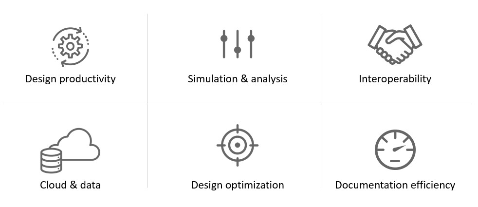
The new features in Autodesk Revit 2024 fall under these six categories:

  • Design productivity
  • Simulation & analysis
  • Interoperability
  • Cloud & data
  • Design optimization
  • Documentation efficiency
Whats New in Autodesk Revit 2024 Categories Moving at the Speed of Business

Design Productivity

General

My Insights in Revit Home

A new My Insights panel has been added to the Revit Home.

By aggregating usage data and finding trends in your workflows, Revit helps you quantify your most common commands and keystrokes, and offers suggestions for how you can optimize and save time when completing design tasks.

It provides information, recommendations, hints and tips to make your work in Revit more effective.

The page displays cards, you can react to these cards and click the Learn more button to access additional online content.

Dark Theme

Revit supports now the Dark Theme for first level user interface, including Properties Palette, Project Browser, Option Bar, Status Bar, View Control Bar. You can also set the drawing area (canvas) theme to Dark or Light both from the ribbon and the Options dialog.

New Sample Model and Project Templates

Use the sample model to learn about features and workflows. The sample model is an example of a mixed use project created using Revit. The model shows examples of how many elements are used to create a project. Examples of construction documents as well as coordinated structural, MEP, site, and point cloud files are included in order to provide a complete model.

Use the Help icons located through the model to learn about specific elements and workflows demonstrated with the model. Track your progress learning about the sample model with the “How Do I?” schedule included in the model. The updated project templates make starting projects and developing your own templates easier.

New Imperial and Metric English “All Discipline” templates are included in a standard installation. The templates include a new starting view, updated fonts, and families loaded for each category.

Modernised Project Browser with New Search

A search function is now available at the top of the Project Browser.

The search starts automatically and updates relevant results as you type. The matched keywords are highlighted in the filtered list on all levels of the hierarchy in the Project Browser.

Save up to 20% on Autodesk Revit and AEC Industry Collection

Colour Books Browser

Improve design deliverables by applying consistent color standards. The new colour books browser replaces how you can select Pantone colors. 

  • Access new color books in dialogs, including Pantone & RAL. 
  • Provides access to Pantone and RAL color books, and the ability to add custom-made color books. 
  • Use the Autodesk Color Book editor to create your custom color book files at
  • Store your custom .acb file under the file path C:\ProgramData\Autodesk\RVT XXXX\ColorBooks

Visit: https://download.autodesk.com/global/acb/index.html to download.

Textures Visual Style

Expand your ability to create impactful representations using the new Textures visual style to apply the texture of render materials without lighting effects.

This style maintains a consistent textural appearance so that a material is always displayed in the same way no matter how it is oriented to the light source.

Revit 2024 to Twinmotion Enhancements

Expedite your renderings updates with the Auto Sync link in Twinmotion with Revit 2024.

  • The Auto Sync functionality has been added to the Twinmotion drop-down menu.
  • Auto Sync supports automatic synchronisation of changes from the active Revit model to the direct link connection in Twinmotion or Unreal Engine.
  • A 3D view needs to be active in order to enable Auto Sync, which is then associated to that 3D view.

Once Auto Sync is enabled while in a 3D view, all visible geometry in this view is automatically kept in sync.

Parameters Sorting in Type/Instance Properties

Project parameters were previously sorted by the date/time of creation, now project parameters are sorted alphabetically in type and instance properties dialogs

Export ‘Family Type’ Parameter

Once you have built your family and defined your family types, you can use the “Family Types” export tool to generate a text file.

In Revit 2024, family type parameter data gets included in the export, helping create a family type catalog with less efforts.

Height Parameter in Scope Box

Get more flexibility when modifying scope box parameters. With the scope box feature, you can control the extents of levels, grids, reference plans, and even the views themselves in plan views.

Height and name parameters have been moved from the Options bar to the Properties palette when creating a scope box in Revit 2024. After a scope box is created, you can edit its height value directly in the Properties palette.

Site Design

Site Design - Toposolids

Improve the quality of your site design with the Toposolid capabilities in Autodesk Revit 2024.

Toposolids represent topography as solid geometry and replaces the Toposurface functionality in previous releases with new icons under the Massing and Site ribbon reflect these new capabilities.

There are two methods to create a Toposolid:

1) Sketch the boundary and and defining elevation points

2) Create it from an import file, either a CAD import or a point file in CSV format.

Existing Toposurfaces upgraded from previous versions can be converted into Toposolids with the “Generate Toposolids” contextual tool. Here you can access the legacy Toposurface settings. Linked topography generated from Civil 3D and hosted in Autodesk Docs will be automatically converted into a Toposolid. The Property Line Data settings is  now available as a stand-alone drop-down menu of the Model Site ribbon panel.

Site Design - Toposolid Properties

Improve the site documentation with expanded surface types by building Toposolids as system families with different instance and type properties, to represent different types of surface sections such as roads and sidewalks, soil infills, grade slabs, sport fields, water bodies, etc.

In Autodesk Revit 2024, each Toposolid type can display different compound layer configurations and different ways of representing contour line intervals.

Toposolids can be set up as a room bound element, suitable for open space programming. The instance properties of a toposolid report a myriad of dimensional parameters, including slope, perimeter, area, volume, elevation, and thickness, among others.

Site Design – Solid Subdivisions

Another Site Design feature in Revit 2024 allows you to design topography features faster and deliver better site plans by defining an area of a toposolid to offset from the original toposolid surface.

For example, you can use sub-divisions to draw parking lots roads, or islands on a toposolid. Creating a sub-division does not result in separate surfaces. Use the split tool to achieve that. Use the instance properties of the sub-division to assign another material to the toposolid.

The sub-division is positively offset from the original surface and must have a thickness > 0. Inherit Contours toggle will display contours from the parent toposolid on the sub-division.

Site Design – Cut and Split Toposolids

Building pads are now retired in Autodesk Revit 2024. Existing pads present in upgraded models can still be edited, but you won’t have the ability to create new ones. To represent an excavation or a tunnel, use cut tools using in-place void-mass families to perform boolean operations. 

In addition, you can cut a Toposolid with elements of multiple categories, including other Toposolids, Ceilings, Floors, Slab Edges, Roofs, Fascia, Gutter, Roof Soffits, Structural Foundations, Walls, Wall Sweeps, Mass Void Forms. Use the Split Tool to freely Split Toposolids in separate element, using sketch lines as the cutting edges. Annotations such as Spot Elevation and Dimensions will remain in place after the split operation. The Split portion with the larges volume will inherit the original ElementID. ​

Site Design – Graded Regions

Reduce your site construction cost with balanced cut and fill analysis. Revit 2024 can report cut and fill volumes on a site to aid in determining the costs of landscape modification during site development.

Apply cut and fill volume analysis to Toposolids using Graded Regions. The grading tool marks an existing Toposolid as demolished and makes a copy with a matching boundary in the current phase .

Grade areas of the topography using the point shape-editor, where you can add, delete, or change the elevation of points. Report the cut and fill volumes of a graded region with a Toposolid schedule. 

Site Design – Show Shape-Edit Control Points

You can preview the display of a Toposolid control points during pre-highlight and selection. Turn off the display of points toggle if you experience performance issues.

The toggle is available as a drop-down panel of the Shape Editing tool. The points will be always accessible when to edit the Toposolid using the Modify sub-element tool.

Site Design – Additional Functionality

Enjoy your site modeling experience with the expanded functionality of Toposolids with it now being easier than ever to model fences that follow the surface of a topography.

Railing now are hosted by Toposolids. In addition, it can host elements from the categories of Site, Parking, Floor Based Elements. Slab edge families can be applied to the edge of a toposolid. For example a slab edge might be used to model a curb edge on your site.

For program developers, Revit 2024 has added APIs for Toposolid-related functions: Toposolid Creations, Generate Toposolid from Toposurface, simplifying Toposolid Points, Subdivision Creations, and Contour Settings.

Rebar

New Path Alignment Options for Freeform Rebar

These new alignment options for the freeform rebar in Revit 2024, increase 3D rebar modeling versatility and help you define the accurate reinforcement for standard and non-standard shapes of concrete elements.

You can now choose how to align the bars in the rebar set and also you can make the bars in the set to be parallel to the planar face selected in the Align/Close constraint. You can also set the alignment options for free form rebar sets, using the Bar Alignment parameter in the Properties palette of the structural rebar or using the in-canvas toggle.

Stirrup Orientation for Aligned Freeform Rebar

Increase 3D rebar modelling versatility by greater control over free form rebars in Revit 2024. You can now toggle the stirrup orientation for the aligned distribution free form rebar by pressing Space bar, however, only applies only for the closed stirrups in the set.

MEP

MEP Fabrication Ductwork Stiffener

Create stiffeners on ductwork with dedicated features with the new MEP Fabrication Ductwork Stiffener command in Autodesk Revit 2024 under the system tab.

This command enables manual placement of loaded stiffener families. Currently stiffener families can be placed and hosted onto straight segments of Fabrication Ductwork. After placement, the hosted stiffener instances would move and resize with the duct segments as users make modifications.

A new family category MEP Ancillary Framing has been added for the basic components used in creating MEP supporting elements such as duct stiffeners, hangers and supports, or equipment racks. Revit 2024 comes with typical Ancillary Framing families used to construct duct stiffeners, including angle irons, struts, rods, angle rings and more.

You can create a schedule with MEP Fabrication Ductwork Stiffener embedded into a Fabrication Ductwork schedule. This allows to more clearly report stiffener data such as stiffener type and their relative location on the duct along with their hosting duct segments, helping with quantification in the fabrication process. Internal stiffeners can be created by constraining internal supporting members such as threaded rods families or conduits families to either side of a duct connector. A built-in parameter is used to differentiate the classification of stiffeners. By setting the parameter value as Internal Stiffeners, Revit creates holes on the stiffener’s hosting ductwork based on shared ancillary framing components.

When you export the fabrication ductwork in a project to a maj. File, hole information will be generated based on internal stiffeners’ locations and shared sub-components. This allows to generate more accurate cut patterns in legacy fabrication products such as Autodesk CAMduct.

Elevation Parameters in Visibility Filters

In Revit 2024, you can easily and accurately control the display of MEP components with visibility filters with access to additional elevation parameters to control the visibility of MEP components in your views.

These improvements to elevation parameters will help you document for installation on sloped MEP segments more efficiently in Revit 2024.

Pipe Wall Thickness as a Built-in Parameter

Revit 2024 has wall thickness as a built-in parameter for pipes to more efficiently create documentation for pipes based on the information available in the model. 

This wall thickness parameter is available for pipe tagging and scheduling. You can also use this wall thickness parameter in view filters to control the appearance of pipes in a view.

Hide Insulation With Hosting Duct and Pipe

Improve efficiency when hiding ducts with insulation. In previous releases of Revit, the insulation remained visible when hiding duct and pipe with insulation, however, now in Revit 2024, the insulation gets hidden regardless the method you use to hide the insulation on duct or pipe elements.

Height Parameter in Scope Box

Get more flexibility when modifying scope box parameters. With the scope box feature, you can control the extents of levels, grids, reference plans, and even the views themselves in plan views.

Height and name parameters have been moved from the Options bar to the Properties palette when creating a scope box in Revit 2024. After a scope box is created, you can edit its height value directly in the Properties palette.

Simulation & Analysis

Solar Study Enhancements

Better visualise the impact of sunlight and shadows. You can access the Sun Settings dialog directly from the ribbon.

Smaller time intervals measured in seconds are now available for single-day solar studies. Study shadows with a higher precision using 15, 30, 45, or 60-second intervals. Drag the sun along its path when using perspective view.

Generate Energy Model by View

Toggle this functionality on or off in the Energy Settings dialog and select a 3D view to create the EAM from to create a faster and more accurate Energy Analytical Model for use in Insight, Systems Analysis and 3rd party tools (via gbXML export). New capabilities for Energy Analysis provide workflow simplification especially when working with linked Architectural models. 3D views can now be chosen to more selectively define what elements are used in Energy Analytical Model creation. This essentially provides an additional means of controlling what elements are used in EAM creation that’s independent from the room bounding setting.

Enhanced Structural Analytical Loads

In Revit 2024, there’s more versatile and accurate definition of structural loads, to improve analytical modeling flexibility. Structural engineers can now apply hosted loads to specific areas of panels and members. Additionally, you can now copy loads to other hosts.

Structural Area Loads With Color Coding

Now in Revit 2024, structural area loads can be presented using color-coding to differentiate load natures which results more clear documentation of the analytical model.

Custom Physical-Analytical Association

Now you can create multiple associations between structural elements to better coordinate updates across the physical and analytical models. 

You can associate multiple analytical panels or members to a single physical object (or vice versa). For example, several analytical panels to represent a single physical floor, several beams associated to a single multi-span analytical member, etc. This new feature helps better coordinate updates across physical and analytical models.

Structural Area Loads With Color Coding

Now in Revit 2024, structural area loads can be presented using color-coding to differentiate load natures which results more clear documentation of the analytical model.

Cloud Data & Interoperability

Link coordination models from Autodesk Docs

The new Link Coordination Model feature with Revit and Autodesk Docs makes it easier for project teams to evolve work together.

  • Keep project files light and your work in synch with your collaborators.
  • Link directly into Revit models and views from any of the 60+ formats supported by Docs and the Autodesk Construction Cloud.
  • Underlay the coordination model as visual reference when designing in Revit and reduce the need for interpretation when coordinating design deliverables with partners and project teams.

Properties of Coordination Model Objects

You can select individual coordination objects by pressing the TAB key until it highlights the element you want to select and get properties of this object displayed in the Properties palette.

These properties are in read-only mode and therefore cannot be edited.

Point Snaps for Coordination Model Objects

Enable fast and convenient snap on coordination model objects. When linking a coordination model into your Revit project, you can snap to coordination model objects.

This is controlled by a new “Snap to Coordination Models” option located in the “Snaps” dialog box.

For example, you can use the “Measure” tool to get a distance between an object in your current Revit project and another object hosted in a linked coordination model.

Properties of Coordination Model Objects

You can select individual coordination objects by pressing the TAB key until it highlights the element you want to select and get properties of this object displayed in the Properties palette.

These properties are in read-only mode and therefore cannot be edited.

Design Optimisation

Dynamo for Revit 2.17 Upgrade

Dynamo 2.17 includes the following features: node recommendations powered by machine learning, settings import and export, graph import to workspace, and more. There are several improvements to Node Autocomplete:

  • Node Recommendations, a new ranking method powered by machine learning and based on graph practices in thousands of training graphs. This method is able to provide more accurate and meaningful node suggestions. This ranking method causes network traffic. If you notice network issues, try switching to the Node Type Match ranking method.
  • When using the Node Recommendations method, each recommended node is shown with a confidence rating, which indicates the algorithm’s confidence that the node is a good choice for the port.
  • The existing Object Type ranking method continues to be available as an option and has been renamed Node Type Match.
  • Node Autocomplete settings are available in Preferences Features  Node Autocomplete.

You can import and export Dynamo settings from the Preferences panel. Settings will be exported as an XML file.

  • When importing, existing settings will be overwritten. To maintain a copy of the current settings, first export your existing settings.
  • For any settings that are not available in the Preferences panel, you’ll need to restart Dynamo (and any host program you may be running) before the imported settings take effect.

Insert graphs into the workspace by going to File Insert and selecting a DYN file. If you already have nodes or a graph in the workspace, the inserted file content will appear below the existing content. To avoid potential issues, Manual run mode will be changed to Automatic.

Also, there are several improvements to the Documentation Browser:

  • Content is reordered and organised into three expandable and collapsible sections: Node Information, Node Issue Help (when applicable), and Inputs and Outputs.
  • Example files in the Node Information section can be navigated using mouse controls or the new control buttons.
  • Visual hierarchy and a modernised look and feel have been implemented.

Dynamo Player & Generative Design Updates

Achieve better design outcomes more efficiently, with these enhancements to Generative Design and Dynamo Player, in Revit 2024. View graph issues and dependencies, add image outputs, and try out new sample graphs in Dynamo Player for Revit 2024.

  • Improvements include: The new Issue Viewer allows you to examine graph issues, including errors and warnings, within Dynamo Player. You can access Issue Viewer from the footer of the Player application after running a graph with at least one error or warning, or from the Options menu.
  • You can examine each graph’s dependencies in Player through the new Graph Dependencies dialog. This dialog provides a quick way to see which packages, external files, or other dependencies your graph needs in order to run properly, enabling you to identify missing dependencies and install them in Dynamo.
  • Two new sample graphs are available: Random Family Instance Placement and Warnings – Isolate Elements.
  • Images are available as outputs in Dynamo Player. The image will update when you make a change and re-run the graph. You can save the image from Player by right-clicking.

Documentation Efficiency

Place Multiple Views and Schedules on a Sheet

Save time when placing views and schedules on sheets. You can place multiple views and schedules on a sheet at the same time, either by dragging them onto the sheet in the drawing area or using the Place View command for views.

The Select View dialog contains a search functionality.

When dragging views (and schedules) onto the sheet, they are positioned tiled on the cursor to make selection and arrangement on the sheet easier.

Move Aligned to Sheet Enhancements

Move multiple elements between sheets while keeping their original positions. The ‘Move View Aligned to Sheet’ command has been generalized to ‘Move Aligned to Sheet’ and expanded to support moving the following sheet-based elements:

  • Views
  • Schedules
  • Panel Schedules
  • Detail Groups
  • Annotation elements
  • Detail elements
  • Revision Clouds and Tags
  • Images

Views, Schedules and Panel Schedules can be moved aligned between sheets directly from the Project Browser.

Views, Schedules, Panel Schedules and all additional sheet-based elements can be moved aligned together directly from the sheet drawing area too.

Open Sheet Directly From Drawing Area

The Open Sheet command allows you to open a sheet from the drawing area.

If you select multiple views from the Project Browser and use this Open sheet command, a confirmation dialog gets displayed with the number of sheets that will be opened.

Schedule Revision Clouds

More easily track and call out changes to document sets with a new Revision Clouds category available now for schedules. You can use fields from Views, Sheets and Revision Clouds to create your Revit schedule. This schedule may also contain schedules key and shared parameters.

Learn More about Autodesk Revit 2024

Check out the Autodesk Revit 2024 Help section for more information regarding the 2024 release.

Ready to get Autodesk Revit 2024?

Discover how Autodesk Vault 2024 can streamline your workflow, increase productivity, and optimise your design process. 

Vault is available from Design Consulting on-premise or cloud, so contact us to discuss which instance suits you best.

Get up to 20% Off Software or Services!

Contact us to find out how much money you can save on software, training or other services. Fill out the form below, by live chat, phone or email.

P: 1800 490 514 |  E: info@designconsulting.com.au

Connected Design

Check out the latest BIM features for architectural, structural and MEP design in What's New for Autodesk Revit 2024

VIEW MORE

February 2023 Autodesk Update: What’s New

Autodesk
Autodesk Banner

Discover the latest news and new features from Autodesk, Click the links below for more information.

 AutoCAD and AutoCAD LT

 Architecture, Engineering & Civil Engineering

 Design & Manufacturing

 Media & Entertainment

 Admin resources and more

 More Information

Contact us on 1800 490 514, info@designconsulting.com.au, by live chat or fill out the form below to get more information on how to best manage your Autodesk software.  Our team of experts have saved our clients thousands of dollars by helping them make smart decisions around how to best structure their investment in technology for maximum return on investment.   We’d be happy to audit your existing technology and recommend any changes that you could benefit from.


Contact Form Demo

VIEW MORE

Autodesk Portal Gets New Usage Reporting Features

Autodesk Portal New Usage Reports Side Bar Moving at the Speed of Business

NEW Autodesk Usage Report

Autodesk have announced that there are new usage reporting features within the Autodesk Account Management Portal for Autodesk accounts.

Coming soon, this new reporting tool will be found under Usage Report. Whether your users are on Autodesk subscriptions or Autodesk Flex licenses, you can now view the product usage details for all of your users on one single page with Usage Report. All admins on all Autodesk plans will have access to the new Usage Report.

Have a look in the reporting section of your account. When the new feature is activated, you will see a snapshot of important details for both subscriptions and Flex. The information available in the new reporting tool ncludes:

  • Total number of Autodesk subscriptions for your team(s)
  • The number of active or inactive users
  • The number of Flex tokens used and Flex tokens remaining
  • The monthly average Flex token usage

You now have easy access to all of this data at your fingertips with a single report showing usage across both Autodesk Flex and Autodesk Subscriptions.

Autodesk Portal New Usage Reports Moving at the Speed of Business

As you scroll down the report you will see a list of users with simple summaries showing:

  • Which Autodesk products they’re using
  • The average number of days they use each product per month
  • How many Flex tokens they’ve used.

You can use the report to differentiate between frequent and infrequent users to adjust and optimize licenses for your team.  For example, you can identify light users and assign them Flex licenses.

Clicking on a user, you can drill down for more detailed information on that particular user as shown below:

Autodesk Portal New Usage Reports User Moving at the Speed of Business

Additionally, you can use filters to arrange your data and identify specific information of interest. For example, you can filter by products, teams or access type. Any filters you apply will also be carried over to the export functionality if you choose to export your data for additional analysis and insights outside of Usage Report, in Microsoft Excel or a Google Sheet for example.

Autodesk Portal New Usage Reports Filter Moving at the Speed of Business

The new Usage Report provides a single view of how all of your Autodesk users are using their licenses. The new Usage Report will help you identify patterns and make better decisions.  For example, the new Usage Report can help you decide:

  • Which users might benefit from using Flex or subscription
  • When to buy more subscriptions or tokens,
  • Which inactive subscriptions you can reassign

Coming Soon

This new reporting feature is not available yet.  When it is launched, you will find it in the Reporting menu as shown below:

Autodesk Portal New Usage Reports Side Bar Moving at the Speed of Business

More Information

Contact us  on 1800 490 514, info@designconsulting.com.au, by live chat or fill out the form below to get more information on how to best manage your Autodesk licenses and tokens.  Our team of experts have saved our clients thousands of dollars by helping them make smart decisions around how to best structure their investment in technology for maximum return on investment.   We’d be happy to audit your existing license structure and recommend any changes that you could benefit from.


Contact Form Demo

VIEW MORE

Plant 3D Toolset Now Included With AutoCAD

Plant 3D Toolset

The 2023 Plant 3D Toolset Is Now Included With AutoCAD

The 2023 Plant 3D Toolset allows you to create and edit P&IDs and 3D models and extract piping orthographics and isometrics. You can now get access to this industry-specific toolset for plant design with your AutoCAD subscription.

With the 2023 Plant 3D toolset, you can:

  • Collaborate securely in a cloud based common data environment 
  • Automate and speed up P&ID drafting and 3D modelling with in-context commands 
  • Automate creation of piping isometric drawings directly from the 3D model  


Plant 3D Toolset Features

See how you can improve efficiency and achieve more with the following AutoCAD Plant 3D toolset features:T


COLLABORATION & P&ID TOOLS

Collaboration For Plant 3D

Collaborate on plant design models across project teams and maintain compliance requirements – all in a cloud-based common data environment.

AutoCAD Plant 3D training course, AutoCAD P&ID training course, AutoCAD Plant 3D course, AutoCAD P&ID course, Collaboration for Plant 3D

Quick P&ID Drafting

Make P&ID drafting easier with in context AutoCAD commands. View the video to learn more.

Industry Standard Symbol Libraries

The Plant 3D toolset is delivered with standard symbol libraries in the tool palettes. These symbol libraries include PIP, ISA, ISO/DIN and JIS libraries.

symbol libraries
data validation large 1920x1080 1 Moving at the Speed of Business

Data Validation

Quickly identify possible errors by scanning P&IDs for data consistency according to user-definable rules.


3D MODELLING TOOLS

Rapid Plant Modelling In 3D

Watch the video to see how you can quickly create 3D plant models using parametric equipment modelling, structural steel libraries and project specific piping specifications using industry standard piping catalogues.

Parametric Equipment Templates

Parametric Equipment Templates

You can create and edit equipment with parametric templates, allowing you to build plant layouts more efficiently.

Structural Modelling

Lay out structures, stairs, ladders and railings using industry-standard steel sections including AISC, CISC and DIN.

Structural Modeling
project specfiic piping specs large 1920x1080 1 Moving at the Speed of Business

Create Project Specific Piping Specs

Customise your piping specifications to meet project specific requirements. You can include industry standard components as well as include customised components.


PIPING DOCUMENTATION

Create And Edit Piping Orthographic Drawings

Extract piping orthographic drawings directly out of your 3D model and update them as the 3D model is being updated.

Piping Orthographic Drawings
Automated production of piping isometrics

Automated Production Of Piping Isometrics

Create industry standard / project standard piping isometric drawings directly out of your 3D model.

Automated Project Specific Reporting

You can define the required report formats for your project and automatically populate the data directly out of your 3D model.

Automated project-specific reporting
BIM model documentation

BIM Model Documentation

Collaborate other industry disciplines to create Building Information Modeling (BIM) models for the entire plant.

Get A Free Consultation

Book a free appointment with one of our Plant 3D experts. Discover how Design Consulting can help your organisation solve problems and take advantage of opportunities with seamless integration of the latest technology into your workflows.  

Contact us  on 1800 490 514, info@designconsulting.com.au, by live chat or fill out the form below to book in a free consultation. We have a team of experts ready to help improve your workflows for maximum return on your technology investment.


Contact Form Demo

VIEW MORE

Free Digital Twin Solution from Autodesk

Tandem 1 Moving at the Speed of Business
Tandem 2.jpg Moving at the Speed of Business

Free Digital Twin Solution from Autodesk

Harnessing BIM to realise Digital Twins Transforming the Built Asset Lifecycle.

Autodesk Tandem is a Digital Twin cloud solution to provide a digital replica of built assets to provide the necessary operation and behavioural awareness to simulate, predict and make informed decisions based on real world conditions.

Autodesk Tandem helps AEC firms harness BIM (Building Information Modelling) data throughout the project lifecycle to create and handover a digital twin. Autodesk Tandem helps owners connect operational systems to the digital twin turning fragmented data into business intelligence.

Tandem 3 Moving at the Speed of Business
Tandem 4 Moving at the Speed of Business

Autodesk Tandem provides flexible and configurable building blocks that will enable AEC firms and owners to create and manage data-rich digital twins that mirror the built environment they represent. This allows for a more integrated workflow, whereby specifying, capturing and verifying the data—and collaboration between owners and project teams—will help achieve the desired operational outcomes.

Get in Touch

DC is an authorised Autodesk Reseller providing products and services for the Architecture, Engineering, Construction, Infrastructure and Manufacturing Sectors.

Feel free to contact us on 1800 490 514, info@designconsulting.com.au, by live chat or fill out the form below.

Contact Form Demo

VIEW MORE

Industry Capabilities Benchmark Report

benchmark capabilities report Moving at the Speed of Business

Industry Capabilities Benchmark Report

Autodesk is continuously working to help businesses as they adapt to an increasingly digital, data-driven, and automated world. A critical component of helping companies thrive, now and in the future, is understanding what capabilities they need to be successful. They collected feedback from over 1000 business leaders and professionals, from 617 companies, across the Building Design, Civil Engineering, Construction, and Manufacturing industries.

Download the report below.

Get in Touch

DC is an authorised Autodesk Reseller providing products and services for the Architecture, Engineering, Construction, Infrastructure and Manufacturing Sectors.

Feel free to contact us on 1800 490 514, info@designconsulting.com.au, by live chat or fill out the form below.

Contact Form Demo

VIEW MORE

Architecture Engineering and Construction Collection

Autodesk Architecture Engineering and Construction Collection - Autodesk AEC Collection

Autodesk Architecture Engineering and Construction Collection

A complete set of BIM tools for the design, analysis, visualisation and documentation of buildings and infrastructure designs and projects.
Revit
Cutting edge BIM software for Architectural, Structural, Mechanical and Electrical 3D modelling, documentation and drafting.
Learn More
AutoCAD
Specialised toolsets for Architecture, Mechanical, Plant, Electrical,GIS design and drafting.
Learn More
Civil 3D
Civil engineering design and analysis
Learn More
Infraworks
Civil infrastructure concept and analysis
Learn More
Advance Steel
Parametric structural steel design and drafting
Learn More
Navisworks Manage
Model coordination, project review, 2D/3D quantity take off, 5D scheduling and clash detection
Learn More
Estore
Get the Architecture Engineering and Construction Collection on an Annual Subscription
Buy Now
Previous slide
Next slide

Overview

What is the Architecture Engineering and Construction Collection?

Compare

Compare the AEC Collection to Revit and Revit LT.

Included Software

See what software is included in the AEC Industry Collection.

Add-ons

Programs and plug-ins to boost productivity.

Pricing

Subscription pricing and comparison to standalone subscriptions.

Blog

Learn about products, workflows and related products.

Overview

The Autodesk AEC Industry Collection is a compilation of software titles for the architecture, engineering, construction and infrastructure industries which give the ability to 3D model, design, visualise, animate, coordinate, simulate, document and draft designs in 2D.

Create high-quality, detailed designs for building and infrastructure projects.
Optimise designs with analysis, generative design, visualisation and simulation tools.
Improve predictability in the field by coordinating and simulating projects and schedules.

The Autodesk AEC Industry Collection is a compilation of software titles for the architecture, engineering, construction and insfrastructure industries which give the ability to 3D model, design, visualise, animate, coordinate, simulate, document and draft designs in 2D.

  • Create high-quality, detailed designs for building and infrastructure projects.
  • Optimise designs with analysis, generative design, visualisation and simulation tools.
  • Improve predictability in the field by coordinating and simulating projects and schedules.

Architectural BIM Workflows

Combine Revit and Insight to improve environmental performance to guide you towards better outcomes using robust analytical tools.
Model in Revit and visualise analysis in Insight such as indicators, benchmark, ranges and specifications on factors such as infiltration, operating schedule, building orientation, lighting efficiency, HVAC, plug load efficiency, payback limit, surface coverage, panel efficiency and effect on construction materials.
Once you have viewed results, you can make design changes in Revit to optimise the building performance using comparison scenarios and viewing the results through the analytical model and produce a calculation summary report to validate design choices.


Infrastructure BIM Workflows

Combine Revit, Civil 3D and Infraworks for bridge analysis and design. Use Civil 3D road geometry to create the initial bridge and develops the design further in Infraworks using parametric rules to change the characteristics of the bridge by individually changing parameters or automate by connecting parameters to a spreadsheet to layout the bridge. Run integrated analysis and design tools to provide feedback during the optioneering phase.
 
Any changes in Civil 3D can be updated in Infraworks thereby providing connected design tools. The bridge structure can be publish to Revit and design work can continue concurrently using 3D structural design tools and 2D documentation.

Generative Design

Create generative design studies to quickly view alternate designs

Structral Design and Analysis Workflows

Combine Revit, Advance Steel and Robot to design, engineer and fabricate structural projects.

3D Scanning BIM Workflows

Pre-process point cloud data for Revit and import 3D scans and work in a hybrid reality capture BIM environment.

Design Automation Workflows

Automate routine tasks that normally take hours into minutes by running Dynamo scripts with applications such as Revit, Civil 3D, FormIT and Advance Steel .

MEP Fabrication Workflows

Connect Revit and CADmep to reduce duplication in designs allowing fabricators to create production designs and documentaion..