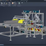
Better Piping and P&ID's Designs with the AutoCAD Plant 3D Toolset

AutoCAD Plant 3D is a powerful toolset for plant design. It offers a wide range of features that are specifically designed for the needs of plant designers and engineers. These features include:
- A comprehensive library of industry-standard symbols
- Powerful 3D modeling tools
- Advanced design automation features
- Integrated reporting and documentation tools
In this blog we’ll explore the differences in using the AutoCAD Plant 3D Toolset over:
- AutoCAD LT and AutoCAD
- MCAD software such as Autodesk Inventor and Dassault Systemes Solidworks
- BIM software such as Revit
Advantages of AutoCAD Plant 3D over AutoCAD LT
AutoCAD LT is a less expensive version of AutoCAD that is designed for 2D drafting and design. It does not offer the same level of features as AutoCAD Plant 3D, including:
- Industry-standard symbols
- 3D modeling tools
- Design automation features
- Integrated reporting and documentation tools
Advantages of AutoCAD Plant 3D over AutoCAD
AutoCAD is a more powerful version of AutoCAD LT that offers a wider range of features. However, it does not offer the same level of specialization for plant design as AutoCAD Plant 3D. AutoCAD Plant 3D includes features that are specifically designed for plant design, such as:
- A comprehensive library of industry-standard symbols
- Advanced 3D modeling tools
- Design automation features
- Integrated reporting and documentation tools
Advantages of AutoCAD Plant 3D over Mechanical CAD Software
Mechanical CAD software is designed for the design of mechanical parts and assemblies. It does not offer the same level of features as AutoCAD Plant 3D for plant design, such as:
- Industry-standard symbols
- Piping and instrumentation diagrams (P&IDs)
- Electrical diagrams
- Structural drawings
- Integrated reporting and documentation tools
Tools: AutoCAD Plant 3D and P&ID vs Autodesk Inventor and SolidWorks
AutoCAD Plant 3D and P&ID tools:
- Industry-standard symbols: AutoCAD Plant 3D and P&ID include a comprehensive library of industry-standard symbols for pipes, valves, fittings, instruments, and other plant equipment. This makes it easy to create accurate and consistent drawings.
- Powerful 3D modeling tools: AutoCAD Plant 3D and P&ID offer powerful 3D modeling tools that allow you to create accurate and realistic models of piping systems.
- Advanced design automation features: AutoCAD Plant 3D and P&ID include advanced design automation features that can help you to speed up the design process and reduce errors.
- Integrated reporting and documentation tools: AutoCAD Plant 3D and P&ID include integrated reporting and documentation tools that can help you to create accurate and professional documentation.
Autodesk Inventor and SolidWorks Pipe and Tubing Tools:
- Parametric modeling: Autodesk Inventor and SolidWorks use parametric modeling, which means that the properties of pipe and tubing components are linked to each other. This can be helpful for maintaining consistency in pipe and tubing designs.
- Clash detection: Autodesk Inventor and SolidWorks include clash detection tools that can help you to identify potential conflicts between pipe and tubing and other components in a design. This can help to avoid costly errors during manufacturing or assembly.
- Generative design: Autodesk Inventor and SolidWorks include generative design tools that can help you to explore different pipe and tubing design options. This can be helpful for finding the most efficient and cost-effective pipe and tubing solutions.
Advantages of AutoCAD Plant 3D over BIM Software
BIM software is designed for the design and construction of buildings. It offers a wide range of features for 3D modeling, clash detection, and quantity takeoff. However, it does not offer the same level of features as AutoCAD Plant 3D for plant design, such as:
- Industry-standard symbols
- P&IDs
- Electrical diagrams
- Structural drawings
- Integrated reporting and documentation tools
Advantages of AutoCAD Plant 3D over BIM Software
BIM software such as Revit is designed for the design and construction of buildings. It offers a wide range of features for 3D modeling, clash detection, and quantity takeoff. However, it does not offer the same level of features as AutoCAD Plant 3D for plant design, such as:
- Industry-standard symbols
- P&IDs
- Electrical diagrams
- Structural drawings
- Integrated reporting and documentation tools
Tools: AutoCAD Plant 3D Vs Revit
AutoCAD Plant 3D Piping Tools
- Industry-standard symbols: AutoCAD Plant 3D includes a comprehensive library of industry-standard piping symbols. This makes it easy to create accurate and consistent piping drawings.
- Powerful 3D modeling tools: AutoCAD Plant 3D offers powerful 3D modeling tools that allow you to create accurate and realistic piping models.
- Advanced design automation features: AutoCAD Plant 3D includes advanced design automation features that can help you to speed up the design process and reduce errors.
- Integrated reporting and documentation tools: AutoCAD Plant 3D includes integrated reporting and documentation tools that can help you to create accurate and professional documentation.
- P&ID Tools: AutoCAD Plant 3D also includes P&ID (Piping and Instrumentation Diagrams) tools that allow you to create accurate and consistent P&ID drawings.
Revit MEP Piping Tools:
- BIM integration: Revit MEP is a BIM (Building Information Modeling) software, which means that it integrates with other BIM software, such as Revit Architecture and Revit Structure. This can be helpful for coordinating piping designs with other aspects of a building design.
- Parametric modeling: Revit MEP uses parametric modeling, which means that the properties of piping components are linked to each other. This can be helpful for maintaining consistency in piping designs.
- Generative design: Revit MEP includes generative design tools that can help you to explore different piping design options. This can be helpful for finding the most efficient and cost-effective piping solutions.
Autodesk Revit and Fabrication Products (Estmep, CADmep and CAMduct) Integration
Revit MEP can connect to Autodesk fabrication products such as ESTmep, CADmep, and CAMduct:
- ESTmep: ESTmep is a software that can be used to generate fabrication drawings and bills of materials for Revit MEP models. It can be used to generate drawings for a variety of HVAC components, such as pipes, valves, and fittings. ESTmep can also be used to generate bills of materials for these components.
- CADmep: CADmep is a software that can be used to create 3D models of HVAC components. These models can then be used to create fabrication drawings and bills of materials. CADmep can also be used to simulate the flow of fluids through HVAC systems.
- CAMduct: CAMduct is a software that can be used to create CNC machine tool paths for HVAC components. These paths can then be used to cut HVAC components from sheet metal. CAMduct can also be used to generate bills of materials for the CNC machine tools.
The Revit MEP can connect to these Autodesk fabrication products through the Autodesk Fabrication Connector. The Autodesk Fabrication Connector is a plugin that allows Revit MEP to export models and data to ESTmep, CADmep, and CAMduct. This allows Revit MEP users to take advantage of the fabrication capabilities of these products.
Here are some of the benefits of connecting Revit MEP to Autodesk fabrication products:
- Increased efficiency: The Autodesk fabrication products can automate many of the tasks involved in fabrication, such as generating drawings and bills of materials. This can help to increase the efficiency of the fabrication process.
- Improved accuracy: The Autodesk fabrication products can help to ensure that fabrication drawings and bills of materials are accurate. This can help to reduce errors and rework during the fabrication process.
- Improved communication: The Autodesk fabrication products can help to improve communication between engineers and fabricators. This can help to ensure that the fabrication process meets the engineer’s specifications.
Plant 3D Setup and Training
To get the most out of Plant 3D, it is recommended to setup Plant 3D and P&ID templates, catalogs and specs and do training. Whether it’s software, training, setup or something custom, Design Consulting has the capabilities to achieve your objectives.
Discover the Right CAD Tool for Your Engineering Needs
Choosing between AutoCAD and AutoCAD Mechanical? Our free eBook offers a detailed comparison to help you make the best choice for your design projects. Gain insights into key features, pricing, and real-world applications.
Download the eBook now to make an informed decision and optimise your workflow.
Tailored Functionality
Organisations can customise AutoCAD for their industries, empowering teams to build and run discipline-specific routines and workflows.

AutoCAD Plant 3D 2024
Ortho Bill of Materials (BOM)
The Ortho Table Setup dialog box includes simplified options and more table capabilities for orthographic drawings. You can now add the Bill of Materials (BOM) for piping, equipment, steel, as well as nozzle and spool lists into ortho drawings.
Spec and Catalog Editor Enhancements
The Edit Parts and Edit Properties functions are enhanced in both Spec and Catalog Editors.
Edit parts within a selected parts family for inclusion in a spec sheet or catalog.

Refer to the 2024 Help file for further information
Pipe Spec Viewer Enhancements
View all parts available for a specific size in the selected spec. Use the search box to look for specific components in the Pipe Spec Viewer.
Any changes to the size and spec lists are both updated in Pipe Spec Viewer and the Part Insertion panel on the ribbon.
Ortho Single-Line Piping Enhancements
In this release, ortho single-line piping offers more enhancements including a new interface for some piping criteria providing better control when you display piping in a single-line representation in orthographic drawings.
Ready to get AutoCAD with the Plant 3D and P&ID Toolset?
Get up to 20% Off Software or Services!
Contact us to find out how much money you can save on software, training or other services. Fill out the form below, by live chat, phone or email.
P: 1800 490 514 | E: [email protected]


