Chat with us, powered by LiveChat

Connected Structural Design with the Autodesk Architecture Engineering and Construction Collection
Learn how the Autodesk AEC Collection connects Advance Steel, Revit and other programs for structural design, analysis and fabrication
Design Consulting Architecture Engineering and Construction Collection logo Moving at the Speed of Business

Connected Structural Design with the Autodesk Architecture Engineering and Construction Collection

The construction industry has seen a significant transformation in recent years with the adoption of new technologies and software. Structural engineering is no exception, as it plays a crucial role in the success of any construction project. Autodesk Architecture, Engineering, and Construction (AEC) Industry Collection is a suite of powerful software tools that enable structural engineers and fabricators to streamline their workflows and improve collaboration.

In this blog post, we will explore how Advance Steel, a software tool within the AEC Industry Collection, works with other applications such as Revit, Autodesk Docs, Robot Structural Analysis, Navisworks, and more to create a connected design process. We will also discuss the benefits of this approach for structural engineers and fabricators on construction projects.

How Does Advance Steel Work With Other Applications in the Collection?

With the AEC Industry Collection, structural engineers can create detailed designs, collaborate with architects and other stakeholders, and analyse their designs for efficiency and safety. Fabricators can use the software to create shop drawings and CNC files, and contractors can use it to manage construction projects and ensure that they stay on schedule and on budget.

Advance Steel is a software tool within the AEC Industry Collection that provides 3D modeling and detailing for steel structures. It is designed to streamline the design and fabrication process for steel structures, making it easier for engineers and fabricators to collaborate and ensure accuracy.

Advance Steel can be used to create detailed steel models in 3D, including connections, plates, and bolts. It also provides tools for creating drawings, bills of materials, and NC files for fabrication. With Advance Steel, engineers and fabricators can ensure that their designs are accurate and meet industry standards.

How Advance Steel works with other applications in the AEC Industry Collection

One of the key benefits of the AEC Industry Collection is that it provides a connected design process. This means that engineers and fabricators can use multiple software tools in the collection to streamline their workflows and ensure accuracy.

Here are some of the ways that Advance Steel works with other applications in the AEC Industry Collection:

  1. Revit: Advance Steel can be used with Revit to create detailed steel models that include all of the necessary information for fabrication. Revit can also be used to create detailed architectural and MEP models, which can be linked to the steel model in Advance Steel for coordination.

  2. Autodesk Docs: Autodesk Docs is a cloud-based document management platform that can be used to store and share project information. With Autodesk Docs, engineers and fabricators can collaborate on design files, RFIs, submittals, and more.

  3. Robot Structural Analysis: Robot Structural Analysis is a software tool that can be used to analyse steel structures for safety and efficiency. With Robot Structural Analysis, engineers can perform finite element analysis (FEA) on their steel models to ensure that they meet industry standards.

  4. Navisworks: Navisworks is a software tool that can be used for project coordination and clash detection. With Navisworks, engineers can import steel models from Advance Steel and other software tools to check for clashes and ensure.

  5. Other Applications: The AEC Industry Collection includes a wide range of other software tools that can be used in conjunction with Advance Steel. For example, Fabrication CADmep can be used to create detailed ductwork and piping models that can be linked to the steel model in Advance Steel for coordination.


Benefits of Connected Design for Structural Engineers and Fabricators

The connected design process enabled by the AEC Industry Collection provides several benefits for structural engineers and fabricators. Here are some of the key advantages:

  1. Improved Collaboration: By using multiple software tools in the AEC Industry Collection, engineers and fabricators can collaborate more effectively. They can share design files, coordinate different aspects of the project, and ensure that everyone is working from the same information.

  2. Streamlined Workflows: The connected design process also streamlines workflows by reducing the need for manual data entry and rework. Engineers and fabricators can move seamlessly between different software tools, and the data is automatically synchronised.

  3. Increased Accuracy: By using software tools like Advance Steel, engineers and fabricators can ensure that their designs are accurate and meet industry standards. They can also perform analysis and simulations to ensure that the structure is safe and efficient.

  4. Faster Time-to-Market: The connected design process enables faster time-to-market by reducing the time needed for design and fabrication. This can help construction companies stay on schedule and avoid delays.

  5. Cost Savings: Finally, the connected design process can also lead to cost savings by reducing the need for rework and minimising errors. This can help construction companies stay on budget and avoid costly mistakes.

Ready to Get Connected?

Save up to 20% on Autodesk Software and Services

How Dynamo is Revolutionising Structural Design with Advance Steel and Revit

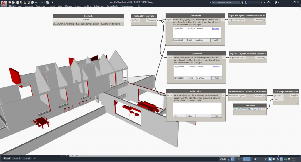
Dynamo is a visual programming tool that is transforming the way structural engineers and designers work. When combined with software tools like Advance Steel and Revit, it offers several benefits that can help streamline workflows and increase efficiency. In this article, we’ll explore the benefits of using Dynamo with Advance Steel and Revit for structural design.

  1. Automating Repetitive Tasks

One of the main benefits of using Dynamo with Advance Steel and Revit is the ability to automate repetitive tasks. For example, Dynamo can be used to automatically create connections between steel elements in Advance Steel based on predefined rules. This can save time and reduce errors, allowing engineers and designers to focus on more complex tasks.

  1. Enhanced Collaboration

Dynamo also improves collaboration between different teams involved in the structural design process. By using a visual programming language, designers and engineers can easily share scripts and workflows with other team members, regardless of their level of technical expertise. This helps to improve communication and ensures that everyone is working from the same information.

  1. Increased Accuracy and Quality

Using Dynamo with Advance Steel and Revit can help improve the accuracy and quality of structural designs. For example, Dynamo can be used to automatically calculate loads and reactions for a structure, or to optimize the size and shape of steel members. This can lead to more efficient and cost-effective designs, as well as better structural performance.

  1. Streamlined Workflows

Dynamo helps to streamline workflows by eliminating the need for manual data entry and reducing the potential for errors. By automating repetitive tasks and using a visual programming language, engineers and designers can move seamlessly between different software tools, saving time and reducing the potential for delays and mistakes.

  1. Improved Visualization

Finally, using Dynamo with Advance Steel and Revit can improve visualisation of the design. With Dynamo, engineers and designers can create complex geometry and parametric models, allowing for greater flexibility and better visualisation of the structure. This can help identify potential issues and make design decisions more effectively.

FeaturesAutoCADAdvance SteelRevit
2D DraftingComprehensive set of 2D drafting tools, including line, circle, polyline, arc, and text toolsLimited 2D drafting tools, including line, circle, and text toolsLimited 2D drafting tools, including line, circle, and text tools
3D ModelingOffers basic 3D modeling tools, including extrude, revolve, and loft toolsOffers more advanced 3D modeling tools, including parametric modeling tools and the ability to automatically generate steel elementsOffers advanced 3D modeling tools, including parametric modeling tools and the ability to create complex geometry
Steel ModelingLimited steel modeling tools, including the ability to create steel elements manuallyOffers more advanced steel modeling tools, including the ability to automatically generate steel elements and parametric modeling toolsOffers basic steel modeling tools, including the ability to create steel elements manually
Steel DetailingLimited steel detailing tools, including the ability to create drawings of steel elementsOffers more advanced steel detailing tools, including the ability to automatically create part drawings, DXF and NC1 files, and CNC data exportOffers basic steel detailing tools, including the ability to create drawings of steel elements
Connection DesignNo connection design toolsOffers comprehensive connection design tools, including the ability to create and analyze connectionsOffers limited connection design tools, including the ability to create basic connections
Structural AnalysisNo structural analysis toolsOffers more advanced structural analysis tools, including the ability to analyze and optimize steel structuresOffers basic structural analysis tools, including the ability to analyze and check steel structures
FabricationNo fabrication toolsOffers comprehensive fabrication tools, including the ability to create shop drawings, CNC data export, and automatic creation of bills of materialsLimited fabrication tools, including the ability to create shop drawings and bills of materials
CollaborationOffers basic collaboration tools, including the ability to share drawings and collaborate on designOffers more advanced collaboration tools, including the ability to connect to Dynamo and synchronize with Revit modelsOffers advanced collaboration tools, including the ability to connect to Dynamo and synchronize with Advance Steel models

AutoCAD offers a comprehensive set of 2D drafting tools, including line, circle, polyline, arc, and text tools. It also offers basic 3D modeling tools, such as extrude, revolve, and loft tools. However, it has limited steel modeling and detailing tools, connection design, structural analysis, and fabrication tools.

Advance Steel offers more advanced steel modeling and detailing tools than AutoCAD. It can automatically generate steel elements, create part drawings, DXF and NC1 files, and export CNC data. It also has comprehensive connection design and fabrication tools. Advance Steel is specifically designed for steel design and fabrication, making it a powerful tool for structural engineers and steel fabricators.

Revit offers advanced 3D modeling tools and basic steel modeling and detailing tools. It can connect to Dynamo and synchronise with Advance Steel models, which makes it an excellent tool for collaboration with architects and other stakeholders in the building design process.

In summary, the choice between AutoCAD, Advance Steel, and Revit depends on the specific needs of the project and the users. AutoCAD is a general-purpose drafting tool, while Advance Steel is specifically designed for steel design and fabrication, and Revit is an excellent tool for collaboration and building design coordination.


Analysing Structural Designs: Advance Steel Vs Revit Vs Robot Structural Analysis

FeatureAdvance SteelRevitRobot Structural Analysis
Finite Element AnalysisYesYesYes
Static AnalysisYesYesYes
Dynamic AnalysisYesNoYes
Buckling AnalysisYesNoYes
Nonlinear AnalysisYesNoYes
Eigenvalue AnalysisYesNoYes
Response Spectrum AnalysisYesNoYes
Pushover AnalysisYesNoYes
Design OptimizationYesNoYes
Steel Connections AnalysisYesNoYes
Concrete AnalysisNoYesYes
Wood AnalysisNoYesYes
Masonry AnalysisNoYesYes
Design Code CompatibilityMultipleMultipleMultiple
Integration with Other ToolsRevit, DynamoNavisworksRevit, Navisworks

Overall, all three software products offer FEA capabilities for structural analysis, including static analysis and finite element analysis. However, Robot Structural Analysis offers more advanced analysis options such as dynamic analysis, buckling analysis, nonlinear analysis, eigenvalue analysis, response spectrum analysis, and pushover analysis. Advance Steel offers the ability to analyze steel connections, while Revit offers analysis options for concrete, wood, and masonry.

In terms of design code compatibility, all three software products support multiple design codes. Additionally, Revit and Robot Structural Analysis can integrate with Navisworks for clash detection and coordination, while Advance Steel and Revit can connect with Dynamo for automation and optimization of structural designs.


Structural Design Collaboration with the AEC Collection

Structural steel design collaboration is a critical aspect of any construction project. Autodesk AEC Collection offers several collaboration tools, including Navisworks and Autodesk Docs, that can help structural engineers collaborate effectively throughout the design and construction process.

Navisworks is a project review and coordination tool that allows engineers and designers to combine models and data from various sources, including Advance Steel and Revit. Navisworks can help identify and resolve potential design conflicts, allowing for more efficient construction planning and reducing the risk of costly errors during construction.

Autodesk Docs is a cloud-based collaboration tool that allows team members to share and access project information, documents, and models from anywhere and on any device. With Autodesk Docs, structural engineers can collaborate in real-time with other team members, including architects, contractors, and owners. The tool can also help track changes, versioning, and approval workflows, ensuring that all team members are working on the latest version of the project documents.

Connected Structural Design

The Autodesk Architecture Engineering and Construction Collection is a powerful suite of software programs that can help architects create better designs and collaborate more effectively with other professionals in the construction industry. By using programs such as Revit, Navisworks, and Docs, architects can create digital models of buildings and share them with other stakeholders, streamlining the design process and reducing errors. By collaborating with MEP/HVAC, Structural and Civil engineers and designers, architects can ensure that their designs are not only visually appealing but also practical and functional, resulting in better-performing buildings that meet safety and regulatory requirements.

Ready to get your Design Connected?

Discover how Autodesk Architecture Engineering and Construction Collection can streamline your workflow, increase productivity, and optimise your design process. 

Get up to 20% Off Software or Services!

Contact us to find out how much money you can save on software, training or other services. Fill out the form below, by live chat, phone or email.

P: 1800 490 514 |  E: info@designconsulting.com.au

Connected Design

The Autodesk Architecture, Engineering and Construction Collection streamlines design, analysis, and visualization for architecture, engineering, construction, infrastructure, and manufacturing industries. The suite of software programs improves efficiency, reduces errors and rework, and increases cost-effectiveness.

Connected Design with Architecture Engineering and Construction Collection

Click a link below to learn more about Connected Design using the Autodesk Product Design & Manufacturing Collection 

VIEW MORE

What’s New in Autodesk Inventor Professional 2024

Check out the latest in mechanical and product design and engineering in What's New in Autodesk Inventor Professional 2024

What's New in Autodesk Inventor Professional 2024

Autodesk Inventor Professional  2024 is out with a focus on new features and over 100 customer driven enhancements for MBD, Part Modeling, Assembly, Drawings, Graphics, Performance, iLogic, Content Center and the API.

Here’s the top features and enhancements in Autodesk Inventor Professional 2024.

General Enhancements

General

It is now possible to set Perspective With Ortho Faces as the default view setting in both Document Settings and Application options.

  • Set ‘Perspective With Ortho Faces’ as the default view setting

Application Options:

  • Display tab > Appearance > Settings >
  • Display Appearance dialog > Initial Display Appearance > Projection

Modeling document:

  • Document Settings > Standard tab > Display Appearance >
  • Settings > Initial Display Appearance > Projection

Graphics

Render Size Limit Removed

Inventor Studio has had, until now, an imposed 4096 x 4096 pixel rendering output. The limitation has been removed and Inventor Studio will render images up to 16K x 16K resolution, depending on what your graphics card supports.

Custom Environment Image Support

The workflow for using custom hdr and exr images with IBL lighting styles is much improved and is supported for both CPU and GPU ray tracing.

Support for IBL backgrounds

GPU ray tracing now supports rendering with IBL backgrounds.

The following enhancements in Graphics have been added:

  • Section view tools expanded
    • Flip
    • Move
    • Rotate
    • End cap
  • Section options added to mini-toolbar
  • Edit and suppress section views in “View Representations”
  • Control Section View end cap preview during section view plane dragging
  • <= 500 parts – end cap shown by default
  • > 500 parts – end cap not shown
  • Override the setting by selecting or deselecting the option in the mini-toolbar
  • Use custom IBL environment
  • GPU ray tracing now supports:
    • IBL environments
    • Threads
  • Ray Tracing UI update

Part Modeling Enhancements

Sheet Metal

Enhanced profile detection on overlapping sketches

Parameter Window

Text and Boolean values can now be exported

  • Boolean has the options of:
    • Text (True or False)
    • Number (0 or 1)
    • Yes or No
  • Hardness

Mark Feature

  • New behaviour section:
    • Project
    • Wrap (new)
  • Choose direction for mark
  • Mark across multiple coplanar surfaces

Assembly Modeling Enhancements

Oriented Minimum Bounding Box

  • Rotate Bounding Boxes to match angle of parts
  • Represents footprint of components more accurately
  • Available in:
    • Simplify
    • Derive
  • Simplify – bounding box edges measured and appear in parameter window

Patterns

Rectangular Pattern

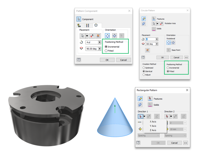
You can now select a revolved face, cylindrical or conical, to define the direction for a component pattern. The Pattern Component command uses the face axis to define the pattern direction. Use the standard controls to flip the direction.

It is not necessary to activate the selector when using an origin axis, clicking the flyout activates the selector and chooses the selected axis. The direction selection does not change with the activation of the selector, you must also select a new direction.

Circular Pattern

Circular pattern for components is enhanced to provide incremental and fitted positioning methods.

Ready to Get Connected?

Save up to 20% on Autodesk Software and Services

New: Finish Feature

The new Finish feature enables you to not only specify the appearance of your parts, components and assemblies, but also the manufacturing process such as material coating or surface finish.

All applied finishes are listed in a new Finishes folder in the browser. You can re-order the finishes in the browser node, suppress, rename or delete them.

In Drawings, a new “Parameters – Finish” type category is added to the Leader Text and the Format Text dialogs to enable Finish information to be used in drawing notes. These parameters will automatically be updated if changed in the modelling environment. This enhances your drawing by adding additional manufacturing process information to the documentation.

Each Finish feature setting has a parameter with corresponding unique name in the “Finish Parameters” category in the Parameters dialog. All Finish parameters can be exported. Exported parameters are displayed in iProperties. Note that change in iProperties doesn’t affect the model finish feature parameters.

The Finish feature can be captured in Model States, iPart an iAssembly.

3D Annotations (MBD) Enhancements

3D Weld Symbols

3D weld symbols are now available as one of the 3D annotation types. Create and edit weld and subweld symbols in a part or assembly model. Then, retrieve the associative symbols in drawings. 3D weld symbols are included in exports to 3D PDF, DWF, and Shared Views.

3DA Envelope Requirement Modifier

The Envelope Requirement modifier is now available for hole notes and dimensions. In the annotation preview, click on a dimension and in the toolbar select the envelope modifier.

Annotation Scale

In this release, 1:5 scale is added to the annotation scale drop down per DIN EN ISO 55455

All Over Modifier

The All Over modifier is now available for feature control annotations.

Drawing Enhancements

Sheet Property

Sheet Name is added as a Sheet Property and can be used in text.

It is now easier to recognize if a filter is applied to the parts list. An icon in the browser and the Parts List dialog displays a filter symbol when one is applied.

Break Line

A change was made to the “Break Out Line” object type for ISO standards. Until now, the “Visible” layer on “Thickness” was set to 0.5 mm. Now, as per the updated standard, the “Break Out Line” object type uses the “Break Line” layer by default with a thickness of 0.25 mm. This also applies to DIN/GB/JIS standards.

Many 2D weld symbols in drawings were updated as per ISO/BSI/DIN/GB standards. The newly introduced 3D weld symbols use ISO, DIN and ANSI standards. The changes include updating the names of fields and adding new fields depending on the selected weld type. The changes were made to Square Butt Welds, Fillet Welds, or Plug Welds for example.

Drawing Line Colour Controls

With this release, color scheme settings can be set for drawing sketch elements. Until now, it was difficult to work with elements if their color conflicted with the sheet color setting. The new Sketch options under the Drafting heading allow the color of sketch elements to be set for the drawing environment.

Revision Clouds

Revision clouds are full-fledged Inventor objects and no longer in the SDK. Add them to drawing sheets or views, move them around, add or delete vertices, and like other annotation styles the formatting is managed using the Styles Editor. Being sketch-based they can be edited either in their cloud state or from the sketch.

Edge Symbol

Starting from this release of Inventor, you can define an Edge Symbol based on ISO 13715:2019 standard. The new Edge Symbol command is added to the Symbols panel of the Annotate tab. The Edge symbol style is added to the drawing Style and Standard Editor.

Tube and Pipe Enhancements

Custom Elbows

In previous versions of Inventor, it was only possible to add a 45 or 90 degree elbow to a rigid pipe run. Starting from this release , it is now possible to apply custom angled elbows.

When a style with Custom Elbows is activated, select the Custom Elbows option in the Route dialog and either use the curved arrow manipulators, or type a value to angle the elbow relative to the current position.

  • When dragged by 45 or 90 degrees, the route is populated with a rigid elbow. Rigid elbow is placed as a Standardpart.
  • When dragged to other than 45 or 90 degrees, the route is populated with a custom elbow. Custom elbow is placed as a Custompart

Minimum and maximum angles are defined in the Custom Angle (CA) column within the Content Center part.

New Custom Elbow Styles

New styles which support the use of custom elbows (Custom Elbow 45, Custom Angle 90) are available in the Tube and Pipe Styles dialog.

iLogic Enhancements

Vault Workflow Enhancements

With Inventor 2024, working with Vault has never been easier. New functions added to iLogic allow Inventor to check out, get files, search Vault, and much more as part of your automations. Vault code snippets added to the editor make it easy to quickly get started.

Add a Custom Content Center Part

You now have the ability to place and define a custom part in iLogic. Create a custom part in Content Center, or insert a standard Content Center part as a custom part, and create a rule to capture the current state. The “AddCustomConterCenterPart” function is created. When you edit the part and repeat the capture operation, iLogic rule updates accordingly. Also, when you edit the rule, the part updates as well.

Close an Open Form

A new function to close an open form is added in this release of Inventor. Note that this is only available for non-modal forms.

Interoperability Enhancements

UCS Support

Both JT and STEP support the option to include UCS on import.

OBJ Import

Performance when opening OBJ files has been improved.

Solid Edge

Support for reading SolidEdge 2023 is added.

Parasolid

Support for importing and exporting Parasolid version 35 is added.

Access to Manual Inspection added to Fusion 360 tools

From within Inventor you can send a part (.ipt) file to Fusion 360 and create manual inspection tasks.

Fusion Exports Workflow

If a change has occurred in the Inventor model state or design view used for a Fusion 360 export, and you click Open in Fusion 360 in the export context menu, you are notified that the Inventor model and Fusion 360 model are out of sync and are given the option to update the Fusion 360 model before opening it.

Learn More about Autodesk Inventor 2024

Ready to get Inventor Professional 2024?

Discover how Autodesk Inventor 2024 can streamline your workflow, increase productivity, and optimise your design process. 

Get up to 20% Off Software or Services!

Contact us to find out how much money you can save on software, training or other services. Fill out the form below, by live chat, phone or email.

P: 1800 490 514 |  E: info@designconsulting.com.au

Connected Design

Check out the latest in mechanical and product design and engineering in What's New in Autodesk Inventor Professional 2024

VIEW MORE

What’s New in Autodesk AutoCAD 2024

check out the latest ion AutoCAD 2024 with specialized toolsets. The essential software for industries such as manufacturing, engineering, construction, and infrastructure. Its industry-specific workflows, such as BIM and collaboration tools, help professionals to create accurate and efficient designs. Features like PDF import, DWG compare, data extraction, dynamic blocks, and layer management make AutoCAD a versatile and powerful tool for 2D drafting and 3D modeling.

What's New in Autodesk AutoCAD 2024

Autodesk AutoCAD 2024 is out with a focus on Accelerating Creativity, Tailored Functionality and a Connected Design Experience.

AutoCAD 2024 Categories Moving at the Speed of Business

Autodesk AutoCAD 2024 Overview

Accelerating Creativity

Focus on quickly creating and collaborating on innovative solutions using assistive machine learning technology to improve design workflows.

The performance enhancements in AutoCAD 2024 really stand out—both with how fast it opens and the speed of switching between models and view ports. It’s much faster than any previous versions.
Michael Shurgalla
Senior Design Technology Specialist, Merrick

Activity Insights

Bridge information gaps in collaborative AutoCAD workflows and stay connected to essential data throughout project lifecycles

My Insights Macro Advisor & Dashboard

Provides valuable information to you at the right time and in the right context to assist with steps that you can automate.

Count & Blocks Palette

Counting blocks is now up to 70% faster and reusing design content with blocks is up to 47% faster.

Autodesk AutoCAD 2024 Macro Advisor. Provides valuable information to you at the right time and in the right context to assist with steps that you can automate.
What's New in Autodesk AutoCAD 2024 - Automatically place blocks in your drawing based on where you’ve inserted the same ones thus far, reducing the number of clicks and saving you valuable time in the process.

Smart Blocks: Placement and Replacement

Automatically place blocks in your drawing based on where you’ve inserted the same ones thus far, reducing the number of clicks and saving you valuable time in the process.

Quickly find the blocks you need with machine learning powered functionality, delivering powerful time-saving automations.

Tailored Functionality

Organisations can customise AutoCAD for their industries, empowering teams to build and run discipline-specific routines and workflows.

Autodesk AutoCAD 2024 Specialised Toolset Moving at the Speed of Business

Ready to Get Connected?

Save up to 20% on Autodesk Software and Services

ACAD for Mac – M series chip

Added support for Apple Silicon increased AutoCAD for Mac’s overall performance by 2x*

Connected Design Experience

Autodesk creates an ecosystem of industry-leading design software and technology partners.

Web AutoLISP APIs

AutoLISP, a staple feature of AutoCAD desktop, now enables customisations to automate a sequence of commands in AutoCAD on the web 

AutoLISP, a staple feature of AutoCAD desktop, now enables customizations to automate a sequence of commands in AutoCAD on the web 

AutoLISP

AutoCAD LT now includes AutoLISP

Leverage thousands of previously written programs created for use in AutoCAD-based programs. AutoCAD LT supports AutoLISP Source (LSP) files, compiled LSP files, Fast-load AutoLISP (FAS), and Visual LISP Applications (VLX) files.

Markup Import & Markup Assist

Faster cross-platform markup workflows through expanded machine learning capabilities & essential experience improvements 

Markup Import & Markup Assist

Faster cross-platform markup workflows through expanded machine learning capabilities & essential experience improvements 

Markup Import Markup Assist​ Moving at the Speed of Business

Migrating Custom Settings

The CUI, tool palettes, and templates have undergone enhancements to facilitate the transfer of customised files and locations.

To utilise personalized configurations:

  1. Access the Autodesk AutoCAD <product and release> folder drop-down list from the Windows Start menu. Choose Migrate From a Previous Release.
  2. In the resulting Migrate Custom Settings dialog box, specify the release you wish to migrate from.
  3. Select the customized settings you want to transfer to the latest release.

Tab Improvements

The Start, File and Layout Tabs have been improved.

Trace Updates

Enhancements to the Trace environment continue, with the introduction of the COPYFROMTRACE command and additional settings controls on the toolbar.

Autodesk Docs Improvements

The following improvements have been made to Autodesk Docs:

  • Improved support and performance when viewing large files on Autodesk Docs.
  • Improved Desktop Connector resulting in improved performance displaying a drawing in the Start tab and opening a drawing from Autodesk Docs.
  • Improved navigation on the Start tab for drawings stored on Autodesk Docs

AutoCAD 2024 Vs AutoCAD LT 2024

AutoCAD 2024 offers more advanced features for 3D modeling, customisation with add-on apps and APIs, rendering, and CAD standards, among other features, while AutoCAD LT 2024 is a more affordable version that still offers many of the essential features for 2D drafting, annotation, and automation. 

FeaturesAutoCAD 2024AutoCAD LT 2024
Find and replace blocks based on other blocks in your drawingYesNo
Stay informed of relevant file changes with details of multi-user activities in a DWG fileYesNo
Utilise AutoLISP programs to automate repetitive tasks and enhance workflowsYesYes
Extend AutoLISP programs with third-party automation libraries, and utilize specialised editors to write and debug programsYesNo
Create and edit 2D geometryYesYes
Annotate drawings with traces, text, dimensions, leaders & tablesYesYes
Customize the ribbon and tool palettesYesYes
Attach and import data from PDF filesYesYes
Share and use data from DGN files, Navisworks, & Bing MapsYesYes
Create and edit 3D models with solids, surfaces, & mesh objectsYesNo
Customize with add-on apps and APIsYesNo
Extract object data to tablesYesNo
Create renderings with lighting, materials, & visual stylesYesNo
Apply and monitor CAD standardsYesNo
Automate counting objects and blocksYesYes
Share drawings with colleagues directly from AutoCAD or AutoCAD LTYesYes
Import feedback and incorporate changes with a click of a buttonYesNo
Learn new features and workflows to work faster with My InsightsYesNo

What's New in Specialised Toolsets

AutoCAD Architecture and MEP 2024

AEC3DPRINT

With AEC3DPRINT command, you can natively export the AEC objects to an STL file format that’s compatible with 3D printing without converting to 3D solids.

Enhanced Design Center Content

New MVBlocks and block references are available in Design Center.

More than 200 new MVBlocks and block references are added to the AutoCAD Architecture (US Imperial) and AutoCAD Architecture (US Metric) content packs for Design Center. The added content is available in metric profile for non-English languages. The content includes external lighting, bathroom accessories, furniture, site, kitchen fittings, and more.

Enhanced Design Center Content Moving at the Speed of Business

Refer to the 2024 Help file for further information 

AutoCAD Mechanical 2024

ANSI/ASME Standard Revision Update

The section line symbol within AutoCAD Mechanical is updated to support the AWS Y14.3 – 2012 standard revision. To support AWS Y14.3 – 2012, all aspects of the section line symbol are revised to correspond with AWS Y14.3 – 2012.

AutoCAD Mechanical continues to support the AWS Y14.3 – 2003 standard revision to allow documents created in previous releases to be opened, edited, and saved without updating the section line symbol standard. By supporting AWS Y14.3 – 2012 and AWS Y14.3 – 2003, you can annotate new and as-built designs using the required standard revision.

ISO Standard Revision Update for Taper and Slope Symbols

The taper and slope symbol within AutoCAD Mechanical is updated to support the ISO 3040:2016(E) standard revision. To support the ISO 3040:2016(E), all aspects of the taper and slope symbol is revised to correspond with ISO 3040:2016(E).

AutoCAD Mechanical continues to support the ISO 3040:2009(E) standard revision to allow documents created in previous releases to be opened, edited, and saved without updating the taper and slot symbol standard. By supporting ISO 3040:2016(E) and ISO 3040:2009(E), you can annotate new and as-built designs using the required standard revision.

Refer to the 2024 Help file for further information 

AutoCAD Plant 3D 2024

Ortho Bill of Materials (BOM)

The Ortho Table Setup dialog box includes simplified options and more table capabilities for orthographic drawings. You can now add the Bill of Materials (BOM) for piping, equipment, steel, as well as nozzle and spool lists into ortho drawings.

Spec and Catalog Editor Enhancements

The Edit Parts and Edit Properties functions are enhanced in both Spec and Catalog Editors.

Edit parts within a selected parts family for inclusion in a spec sheet or catalog.

The Edit Parts and Edit Properties functions are enhanced in both Spec and Catalog Editors. Edit parts within a selected parts family for inclusion in a spec sheet or catalog.

Refer to the 2024 Help file for further information 

Pipe Spec Viewer Enhancements

View all parts available for a specific size in the selected spec. Use the search box to look for specific components in the Pipe Spec Viewer.

Any changes to the size and spec lists are both updated in Pipe Spec Viewer and the Part Insertion panel on the ribbon.

Ortho Single-Line Piping Enhancements

In this release, ortho single-line piping offers more enhancements including a new interface for some piping criteria providing better control when you display piping in a single-line representation in orthographic drawings.

AutoCAD Map 3D 2024

Coordinate System Update

AutoCAD Map 3D 2024 supports the new coordinate systems in the following categories:

  • SnakeGrid EWR2
  • NAD83(CSRS) / Alberta 3TM

Refer to the 2024 Help file for further information 

AutoCAD Electrical 3D 2024

Pipe Spec Viewer Enhancements

Create a schematic symbol table from schematic reports.

The schematic report lists the symbols used in the project along with its description in a table. You can also surf through a particular symbol that is used in various locations of the project.

Wire Type Synchronisation

Wire type can now be synchronized for all wires in the network with the same signal code across the drawings.

In previous releases, when you update the type of the wire connected to the source arrows, the destination wire type was not updated. In AutoCAD Electrical 2024 toolset, when the wire type is updated at the source arrow, all wires in the network are updated to the same wire type of the source. New wire layers are created along with its properties if the destination drawing doesn’t contain the new wire type.

Refer to the 2024 Help file for further information 

Ready to get AutoCAD 2024?

Discover how Autodesk AutoCAD 2024 can streamline your workflow, increase productivity, and optimise your design process. 

Get up to 20% Off Software or Services!

Contact us to find out how much money you can save on software, training or other services. Fill out the form below, by live chat, phone or email.

P: 1800 490 514 |  E: info@designconsulting.com.au

Connected Design

Buy Autodesk AutoCAD 2024

AutoCAD 2024 Brochures

PDF Logo small Moving at the Speed of Business
AutoCAD 2024 Brochure
PDF Logo small Moving at the Speed of Business
AutoCAD LT 2024 Brochure
PDF Logo small Moving at the Speed of Business
AutoCAD vs AutoCAD LT 2024

VIEW MORE

Connected Infrastructure Design with the Autodesk Architecture Engineering and Construction Collection

Connected infrastructure design with the Autodesk Architecture Engineering and Construction Collection
Design Consulting Architecture Engineering and Construction Collection logo Moving at the Speed of Business

Connected Infrastructure Design with the Autodesk Architecture Engineering and Construction Collection

Civil engineering projects involve complex designs and planning. For a successful project, the various components of the design and planning process must work together seamlessly. Autodesk’s Architecture Engineering and Construction Industry Collection offers a suite of software tools that allow for connected design in infrastructure projects. The collection integrates different applications, including Civil3D, Revit, Autodesk Docs, and InfraWorks, to enable civil engineers to work collaboratively and efficiently. This blog post will explore how Civil3D works with other applications in the collection, the benefits of connected design for civil engineers, and infrastructure projects.

How Does Civil3D Work With Other Applications in the Collection?

Civil3D is a software tool for civil engineers that helps in the design and analysis of infrastructure projects such as roads, highways, and land development. Civil3D works seamlessly with other applications in the collection to allow for connected design in infrastructure projects.

Revit is a software tool for architects and engineers that allows for the creation of detailed building models. Revit can import Civil3D data, allowing architects to see how buildings interact with the surrounding infrastructure.

Autodesk Docs is a cloud-based document management system that enables teams to collaborate on project documentation in real-time. Civil engineers can use Autodesk Docs to manage project documentation, including design plans, construction schedules, and specifications.

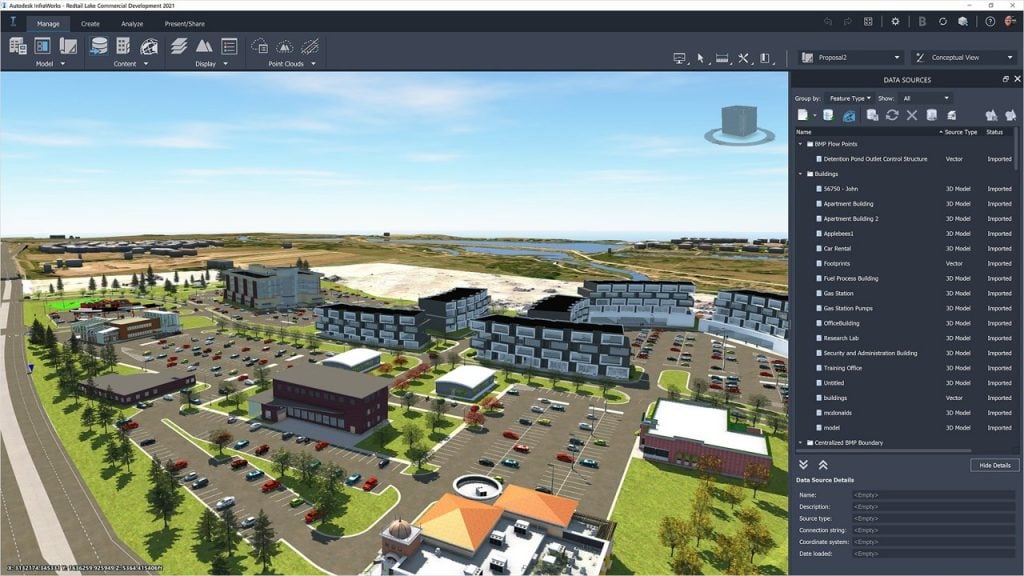
InfraWorks is a software tool that allows for the creation of 3D models of infrastructure projects. Civil engineers can use InfraWorks to visualize the impact of infrastructure projects on the surrounding environment. InfraWorks can also import data from Civil3D, enabling the creation of detailed 3D models of infrastructure projects.

The Benefits of Connected Design for Civil Engineers and Infrastructure Projects

Connected design offers several benefits for civil engineers and infrastructure projects. Let’s explore some of these benefits in more detail.

Improved Collaboration

One of the main benefits of connected design is improved collaboration between engineers and other members of the project team. By using software tools like Civil3D, Revit, Autodesk Docs, and InfraWorks, engineers can work together in real-time to make changes and updates to the model. This collaborative approach can lead to more efficient and effective decision-making, which can ultimately save time and reduce errors in the design process. Connected design also allows for better communication between team members, as everyone has access to the same data and can easily share their ideas and feedback.

Streamlined Design Process Connected design also streamlines the design process for civil engineers. With software tools like Civil3D, engineers can create accurate and detailed 3D models of their designs, which can be easily imported into other applications like Revit and InfraWorks. This integration between different software tools eliminates the need for manual data transfer, which can be time-consuming and error-prone. The streamlined design process also allows for faster iteration and decision-making, as engineers can quickly make changes and updates to the model based on feedback from other team members.

More Accurate and Detailed Modeling

Connected design enables civil engineers to create more accurate and detailed models of their designs. With software tools like Civil3D, engineers can create 3D models that accurately represent the real-world conditions of the project site. This level of detail allows engineers to analyze and test their designs more thoroughly, which can help identify potential issues and prevent costly mistakes during construction. More accurate and detailed modeling also enables engineers to optimize their designs for efficiency, reducing the overall cost and environmental impact of the project.

Better Data Management Connected design also provides better data management for civil engineers. With software tools like Autodesk Docs, engineers can store and manage all project data in one central location. This eliminates the need for manual data transfer and ensures that all team members have access to the most up-to-date information. Better data management also enables engineers to track changes and updates to the design over time, which can be helpful for future maintenance and repairs.

Enhanced Visualisation

Finally, connected design enables enhanced visualization for civil engineers. With software tools like InfraWorks, engineers can create 3D models of entire cities and infrastructure projects, which can be used to visualize the impact of the project on the surrounding environment. Enhanced visualization can also be helpful for presenting designs to stakeholders and the public, as it provides a clear and detailed representation of the project.

Unlocking the Potential of Connected Civil Engineering Design with Autodesk's AEC Industry Collection

Civil 3D, InfraWorks, and Revit are all part of the Autodesk Architecture, Engineering, and Construction (AEC) industry collection, and are designed to work together for connected design workflows.

InfraWorks is used for creating and visualizing large-scale infrastructure projects, such as roads, highways, and airports. It provides tools for creating 3D models of proposed designs, analyzing the impacts of these designs on the surrounding environment, and sharing and collaborating with other stakeholders.

Civil 3D, on the other hand, is focused on detailed civil engineering design, such as grading, drainage, and road design. It allows for the creation of detailed design models, analysis of earthwork quantities, and the creation of construction documentation.

Revit is a BIM software that provides tools for creating and managing detailed 3D models of buildings and structures. It can be used to create and analyze structural designs, as well as to manage building information throughout the design and construction process.

When used together, these tools enable a connected design workflow that allows for the creation and analysis of both the infrastructure and the buildings and structures that will be integrated into it. InfraWorks can be used to create a preliminary design of the infrastructure project, which can then be imported into Civil 3D for detailed design and analysis. Revit models can also be integrated into the design process, allowing for the creation of detailed building information models that can be analyzed in the context of the surrounding infrastructure.

Overall, the connected design workflow enabled by these tools allows for greater collaboration and efficiency throughout the design and construction process, leading to better outcomes for infrastructure projects.


Ready to Get Connected?

Save up to 20% on Autodesk Software and Services

AutoCAD vs. AutoCAD Civil 3D vs. Revit

AutoCAD is a general-purpose CAD software used for 2D drafting and 3D modeling, whereas Civil 3D is specifically designed for civil engineering tasks such as road design and land development. Revit is a BIM software used for building design and construction documentation. While AutoCAD and Civil 3D are more focused on geometric design, Revit allows for the creation of detailed 3D models with parametric design features. Civil 3D and Revit also offer collaboration features such as cloud-based sharing and real-time updates, which are not available in AutoCAD. The choice between these software depends on the specific needs and tasks of the project.

FeaturesAutoCADCivil 3DRevit
2D DraftingYesNoYes
3D ModelingYesYesYes
Geometric DesignYesYesLimited
Civil Engineering DesignNoYesYes
Road DesignNoYesLimited
Land DevelopmentNoYesLimited
BIM FeaturesNoNoYes
Parametric DesignNoNoYes
Cloud-Based SharingNoYesYes
Real-Time UpdatesNoYesYes
Bridge DesignNoYesYes
TopographyNoYesYes
Civil Structural EngineeringNoYesYes


Civil 3D vs. Infraworks

Civil 3D and InfraWorks are both part of the Autodesk AEC industry collection and are commonly used for civil engineering and infrastructure design projects. While they share some similarities, they have distinct differences in terms of their focus and capabilities.

Civil 3D is primarily focused on detailed design for civil engineering projects, such as grading, drainage, and road design. It is a powerful tool for creating accurate 3D models of proposed designs and analysing earthwork quantities, as well as for creating construction documentation. Civil 3D is ideal for engineers who need precise control over the design process and require a high level of detail and accuracy.

InfraWorks, on the other hand, is focused on conceptual design and visualization for large-scale infrastructure projects, such as highways, airports, and rail networks. It provides tools for creating 3D models of proposed designs, analyzing the impacts of these designs on the surrounding environment, and sharing and collaborating with other stakeholders. InfraWorks is ideal for early-stage design, where the focus is on understanding the potential impacts of a project and communicating that information to stakeholders.

When used together, Civil 3D and InfraWorks enable a connected design workflow that allows for the creation and analysis of both the detailed civil engineering design and the larger-scale infrastructure design. Civil 3D can be used to create detailed design models, which can then be imported into InfraWorks for visualisation and analysis in the context of the surrounding environment. InfraWorks models can also be used to create preliminary designs that can be refined and detailed in Civil 3D.

A feature comparison matrix for Civil 3D and InfraWorks might include the following:

FeatureCivil 3DInfraWorks
Detailed designYesNo (focused on conceptual design)
Earthwork quantitiesYesNo
Terrain modelingYesYes
Analysis toolsYesYes
VisualisationLimited (focused on detailed design)Extensive (focused on conceptual design)
CollaborationLimited (focused on detailed design)Extensive (focused on conceptual design)

Overall, the connected design workflow enabled by Civil 3D and InfraWorks allows for greater collaboration and efficiency throughout the design and construction process, leading to better outcomes for infrastructure projects. Civil 3D is ideal for detailed design, while InfraWorks is ideal for early-stage design and visualisation.

Empowering Civil Engineering Design with Dynamo for Civil 3D: Streamline Workflows and Boost Efficiency

Dynamo for Civil 3D is a powerful tool that allows users to automate complex design tasks and create custom workflows for Civil 3D. Dynamo is a visual programming language that can be used to create custom scripts that automate repetitive design tasks, such as creating road alignments, profiles, and surfaces.

With Dynamo, Civil 3D users can create custom tools and workflows that are tailored to their specific project needs. For example, users can create scripts that automatically generate designs based on predefined parameters, or scripts that analyze and optimize designs for cost and efficiency.

The use of Dynamo for Civil 3D can significantly streamline the design process, reduce errors, and improve project outcomes. By automating repetitive tasks, engineers and designers can focus on higher-level design decisions and creative problem-solving.

Connected Infrastructure Design

The Autodesk Architecture Engineering and Construction Collection is a powerful suite of software programs that can help architects create better designs and collaborate more effectively with other professionals in the construction industry. By using programs such as Revit, Navisworks, and Docs, architects can create digital models of buildings and share them with other stakeholders, streamlining the design process and reducing errors. By collaborating with MEP/HVAC, Structural and Civil engineers and designers, architects can ensure that their designs are not only visually appealing but also practical and functional, resulting in better-performing buildings that meet safety and regulatory requirements.

Ready to get your Design Connected?

Discover how Autodesk Architecture Engineering and Construction Collection can streamline your workflow, increase productivity, and optimise your design process. 

Get up to 20% Off Software or Services!

Contact us to find out how much money you can save on software, training or other services. Fill out the form below, by live chat, phone or email.

P: 1800 490 514 |  E: info@designconsulting.com.au

Connected Design

The Autodesk Architecture, Engineering and Construction Collection streamlines design, analysis, and visualization for architecture, engineering, construction, infrastructure, and manufacturing industries. The suite of software programs improves efficiency, reduces errors and rework, and increases cost-effectiveness.

Connected Design with Architecture Engineering and Construction Collection

Click a link below to learn more about Connected Design using the Autodesk Product Design & Manufacturing Collection 

VIEW MORE

Connected Architecture Design with the Autodesk Architecture Engineering and Construction Collection

Connected Architecture Design with the Architecture Engineering and Construction Collection
Design Consulting Architecture Engineering and Construction Collection logo Moving at the Speed of Business

Connected Architecture Design with the Autodesk Architecture Engineering and Construction Collection

The field of architecture has come a long way from hand-drawn sketches and blueprints. With the rise of technology, architects now have access to a wide range of software tools that can help them design and construct buildings more efficiently. One such tool is the Autodesk Architecture Engineering and Construction (AEC) Collection, a suite of software programs designed to facilitate connected design and collaboration among architects, engineers, and other construction professionals.

Understanding Autodesk AEC Collection

The Autodesk AEC Collection is a comprehensive suite of software programs that includes tools for building information modeling (BIM), 2D and 3D design, visualization, and analysis. It includes software programs such as Revit, AutoCAD, Navisworks, and Docs, among others. By using the AEC Collection, architects can create, manage, and share their design data more effectively, resulting in a more streamlined and efficient design process.

The Benefits of Connected Architecture Design

Connected design refers to the process of collaborating with other professionals involved in the construction process. By working together and sharing information, architects, engineers, and builders can reduce errors, speed up the design process, and ultimately create better buildings. Connected design also enables architects to incorporate feedback from other stakeholders, resulting in a more comprehensive and effective design.

Collaborating with Revit in AEC Collection

One of the key tools in the AEC Collection is Revit, a BIM software program that allows architects to design and collaborate on building projects in real-time. Revit enables architects to create a digital model of a building, complete with all the necessary information, such as dimensions, materials, and structural details. This model can then be shared with other professionals in the construction process, such as engineers and builders, to facilitate collaboration and ensure a more efficient design process.

Ready to Get Connected?

Save up to 20% on Autodesk Software and Services

Connecting with Navisworks and Docs

Navisworks and Docs are two other software programs included in the AEC Collection that can help streamline the design process. Navisworks is a project review software that allows architects and engineers to visualise and analyse their designs in 3D. This can help identify any potential clashes or issues before construction begins, reducing the likelihood of errors and delays. Docs, on the other hand, is a cloud-based collaboration tool that enables architects to share and manage design data with other professionals in real-time, from any location.

AutoCAD vs. AutoCAD Architecture vs. Revit

While all three software programs are used in the architecture industry, they serve different purposes. AutoCAD is a 2D drafting and design software program, while AutoCAD Architecture is a 3D design tool specifically for architects. Revit, on the other hand, is a BIM software program that enables architects to create digital models of buildings with all the necessary information. While each program has its own strengths and weaknesses, architects can use them together in the AEC Collection to create a more comprehensive and effective design.

Tool/CommandAutoCADAutoCAD ArchitectureRevit
2D drafting✔️  
3D design ✔️✔️
Walls ✔️✔️
Doors ✔️✔️
Windows ✔️✔️
Stairs ✔️✔️
Roofs ✔️✔️
Slabs/Floors ✔️✔️
Structural elements  ✔️
MEP/HVAC  ✔️
Building Information Modelling (BIM)  ✔️

Collaboration with Other Disciplines in AEC Collection:

The AEC Collection also includes software programs designed for MEP/HVAC, Structural and Civil engineering and design. By working together with these professionals, architects can ensure that their designs are not only visually appealing but also practical and functional. MEP/HVAC software programs such as AutoCAD MEP and Revit MEP enable architects to create accurate and detailed mechanical, electrical, and plumbing (MEP) systems. This ensures that these systems are integrated seamlessly into the building design, resulting in better performance and energy efficiency.

Structural engineering software programs such as Revit Structure and Robot Structural Analysis can help architects design structurally sound buildings that can withstand various forces and loads. By incorporating these programs into the design process, architects can create more efficient and cost-effective designs that meet safety requirements.

Civil engineering software programs such as AutoCAD Civil 3D and InfraWorks enable architects to design roadways, bridges, and other infrastructure projects with accuracy and precision. By working together with civil engineers, architects can ensure that their designs are integrated into the surrounding environment and meet the necessary safety and regulatory requirements.

Connected Architecture Design

The Autodesk Architecture Engineering and Construction Collection is a powerful suite of software programs that can help architects create better designs and collaborate more effectively with other professionals in the construction industry. By using programs such as Revit, Navisworks, and Docs, architects can create digital models of buildings and share them with other stakeholders, streamlining the design process and reducing errors. By collaborating with MEP/HVAC, Structural and Civil engineers and designers, architects can ensure that their designs are not only visually appealing but also practical and functional, resulting in better-performing buildings that meet safety and regulatory requirements.

Ready to get your Design Connected?

Discover how Autodesk Architecture Engineering and Construction Collection can streamline your workflow, increase productivity, and optimise your design process. 

Get up to 20% Off Software or Services!

Contact us to find out how much money you can save on software, training or other services. Fill out the form below, by live chat, phone or email.

P: 1800 490 514 |  E: info@designconsulting.com.au

Connected Design

The Autodesk Architecture, Engineering and Construction Collection streamlines design, analysis, and visualization for architecture, engineering, construction, infrastructure, and manufacturing industries. The suite of software programs improves efficiency, reduces errors and rework, and increases cost-effectiveness.

Connected Design with Architecture Engineering and Construction Collection

Click a link below to learn more about Connected Design using the Autodesk Product Design & Manufacturing Collection 

VIEW MORE

Connected Design with the Autodesk Architecture Engineering and Construction Collection

The Autodesk Architecture, Engineering and Construction Collection streamlines design, analysis, and visualization for architecture, engineering, construction, infrastructure, and manufacturing industries. The suite of software programs improves efficiency, reduces errors and rework, and increases cost-effectiveness.
Design Consulting Architecture Engineering and Construction Collection logo Moving at the Speed of Business

Connected Design with the Autodesk Architecture Engineering and Construction Collection

In today’s fast-paced world, the construction industry is continuously evolving with new technology advancements. As technology advances, it becomes essential to have an efficient and connected design process that incorporates design, analysis, and visualization. The Autodesk Architecture, Engineering and Construction Collection is a comprehensive suite of software programs that facilitate this process. This blog post will discuss how the Autodesk Architecture, Engineering and Construction Collection can benefit various industries by connecting design, analysis, and visualization.

Connected Design Workflow: How Software Programs Work Together

The Autodesk Architecture, Engineering and Construction Collection consists of multiple software programs that allow for a connected design workflow. The software programs in the collection work together seamlessly, allowing for efficient design, analysis, and visualization. The collection includes software programs such as AutoCAD, Revit, Navisworks, and more. Each software program is designed to perform a specific task, and when used together, they create a comprehensive design workflow.

Designing with Precision: AutoCAD and Revit in the AEC Collection

The first step in any construction project is design. The Autodesk Architecture, Engineering and Construction Collection includes various software programs that aid in the design process. AutoCAD is a widely used software program that allows for 2D and 3D drafting. AutoCAD is used to create detailed drawings, and it is compatible with other software programs in the collection. Revit is another software program that is used in the design process. Revit allows for BIM (Building Information Modelling), which helps in creating a detailed 3D model of the building. By using Revit, the design process becomes more efficient, as the software program allows for collaboration between various stakeholders.

Revit and Civil 3D: Enhancing Infrastructure and Construction Projects with 3D Modeling and Efficient Design Collaboration

Revit and Civil 3D are commonly used in the AEC industry for infrastructure and construction projects. Revit creates 3D models of buildings, while Civil 3D designs infrastructure projects. Used together, they complement each other and improve the design process by identifying potential design issues in 3D models. Changes made in one software program are automatically updated in the other. This streamlines the design process and helps identify issues early in the design phase.

Ready to Get Connected?

Save up to 20% on Autodesk Software and Services

How Revit and Advance Steel Work Together to Streamline Steel Design and Fabrication

Revit and Advance Steel are two software programs that can be used together in the architecture, engineering, and construction (AEC) industry. Revit is a building information modeling (BIM) software that is used to create 3D models of buildings, while Advance Steel is a 3D modeling software that is used to design steel structures.

When used together, Revit and Advance Steel can improve the efficiency and accuracy of the design process. For example, an engineer can create a 3D model of a building in Revit and then export it to Advance Steel to design the steel structure. The engineer can then import the steel structure design back into Revit to ensure that it is compatible with the rest of the building design.

In addition, when changes are made in one software program, they are automatically updated in the other software program. This means that any changes made to the steel structure design in Advance Steel will be automatically reflected in the building design in Revit, and vice versa.

Using Revit and Advance Steel together can also help identify potential design issues early in the design phase. The 3D models created in Revit and Advance Steel can be used to identify clashes or conflicts that may have been missed in 2D design drawings. This can help save time and reduce the risk of errors and rework later in the project.

In conclusion, Revit and Advance Steel are powerful software programs that can be used together to improve the efficiency and accuracy of the design process in the AEC industry. The ability to export and import design elements between the two software programs and ensure that changes are automatically updated can streamline the design process and help identify potential issues early in the design phase.

Efficient Analysis with Navisworks and Autodesk Robot Structural Analysis Professional

The Autodesk Architecture, Engineering and Construction Collection includes software programs that aid in the analysis process. Navisworks is a software program that allows for coordination and simulation of construction projects. Navisworks helps in identifying clashes, reducing errors and rework, and creating more efficient designs. Additionally, Autodesk Robot Structural Analysis Professional is used to perform structural analysis of buildings. The software program helps in identifying structural deficiencies and optimizes the design process.

Bringing GIS Mapping and Connected Design Together: A Comprehensive Approach with Autodesk's AEC Collection

In today’s world, design and construction projects require a more comprehensive approach than ever before. With the Architecture Engineering and Construction (AEC) Collection from Autodesk, architects, engineers, and construction professionals have access to a suite of powerful tools that can help them collaborate and work more efficiently. One of the most valuable features of the AEC Collection is its ability to integrate with Geographic Information Systems (GIS) mapping, providing a more accurate and detailed view of project sites and landscapes.

AutoCAD Map 3D is a powerful software tool for GIS mapping, which allows users to access, manage and analyse spatial data. With AutoCAD Map 3D, users can easily import and export data from various sources, such as aerial imagery, satellite imagery, and other GIS data. This software also provides a wide range of tools for data analysis, visualization and editing, making it an essential tool for GIS professionals. Some of the key features of AutoCAD Map 3D include 3D modelling and visualisation, data query and analysis, and advanced geospatial analysis tools. By leveraging these features, users can create accurate and comprehensive maps and spatial data sets for a wide range of applications.

GIS mapping is a critical component of many construction projects, particularly those that involve large-scale developments or infrastructure. By overlaying geographic data such as topography, hydrology, and geology onto a digital map, project teams can better understand the context of their projects and make more informed decisions. The AEC Collection’s integration with GIS mapping tools allows architects, engineers, and construction professionals to access this data within their design software, creating a more seamless and connected workflow.

With the AEC Collection, design professionals can also collaborate with each other in real-time using tools such as Navisworks and Docs. Navisworks allows teams to integrate and coordinate models from multiple disciplines, while Docs enables document management and sharing across teams. By using these tools in conjunction with GIS mapping, project teams can ensure that all stakeholders have access to the most up-to-date information, reducing errors and improving overall project efficiency.

Enhancing Oil and Gas Plant Design with the AEC Collection and Plant 3D

The Architecture Engineering and Construction (AEC) Collection is a powerful suite of software programs designed to facilitate connected design for the architecture industry. One of the key software programs in this collection is Plant 3D, which is specifically designed for oil and gas plant design.

Plant 3D is a comprehensive software program that enables users to design, model, and analyze piping and instrumentation diagrams (P&ID) for oil and gas plants. With its intuitive interface and advanced tools, Plant 3D allows users to create accurate and detailed 3D models of plant layouts, equipment, and piping systems.

One of the key advantages of using the AEC Collection and Plant 3D for oil and gas plant design is the ability to collaborate with other disciplines in the industry, such as civil engineering and structural design. By working together in a connected design environment, designers and engineers can ensure that all aspects of the plant design are integrated seamlessly, from the initial concept through to construction and operation.

In addition, the AEC Collection and Plant 3D offer a range of powerful tools for data management and analysis, enabling users to track and monitor plant performance, optimize plant layouts, and identify potential safety hazards or operational issues.

Some of the key features of Plant 3D include:

  • Intelligent P&ID design and management tools
  • Comprehensive 3D modeling capabilities
  • Advanced piping and instrumentation analysis tools
  • Integration with other AEC Collection software programs, such as Navisworks and Docs

By leveraging these features, designers and engineers in the oil and gas industry can streamline their design processes, improve collaboration, and ensure that their plant designs are optimized for safety, efficiency, and performance.

Enhancing Visualisation with 3DS Max and InfraWorks

Visualisation is an essential part of any construction project. The Autodesk Architecture, Engineering and Construction Collection includes software programs that aid in the visualization process. 3DS Max is a software program that allows for rendering and animation of 3D models. 3DS Max helps in creating realistic visuals, which help in selling designs to clients. Autodesk InfraWorks is another software program that helps in creating visualizations of infrastructure projects. InfraWorks allows for collaboration between various stakeholders, and it helps in creating a more efficient design process.

Streamlining AEC Projects with Autodesk Docs

Autodesk Docs is a powerful document management tool that can help streamline AEC projects when used in conjunction with the Architecture Engineering and Construction Collection (AEC Collection) software. The AEC Collection includes several software programs that are essential for building design and construction, including Revit, Civil 3D, and Advance Steel.

By using Autodesk Docs to manage project documents, stakeholders can easily access and collaborate on project files from anywhere, at any time. This can improve project efficiency and communication, as all team members can stay up-to-date on project progress and changes.

Moreover, the AEC Collection software can be seamlessly integrated with Autodesk Docs, allowing users to store and manage their project files directly within Autodesk Docs. This integration makes it easier for teams to collaborate on project files and ensures that all project documentation is stored in one place, reducing the risk of lost or missing files.

For example, Revit models can be directly linked to Autodesk Docs, allowing team members to access and collaborate on the most up-to-date model at all times. Civil 3D designs can also be stored in Autodesk Docs, making it easy to share and collaborate on complex civil engineering projects.

Overall, by using Autodesk Docs in conjunction with the AEC Collection software, AEC professionals can streamline their project workflows, improve collaboration and communication, and ensure that project documentation is secure and easily accessible.

AEC Collection in Various Industries: Architecture, Engineering, Construction, Infrastructure, and Manufacturing

The Autodesk Architecture, Engineering and Construction Collection is beneficial to various industries. Here are a few examples:

Architecture: The Autodesk Architecture, Engineering and Construction Collection is used by architects to design and visualise buildings. The software programmes in the collection allow for efficient design, analysis, and visualisation.

Engineering: Engineers use the Autodesk Architecture, Engineering and Construction Collection to perform structural analysis and design. The software programmes in the collection help in identifying structural deficiencies, optimising designs, and creating efficient designs.

Construction: The Autodesk Architecture, Engineering and Construction Collection is used in the construction industry to coordinate and simulate construction projects. The software programmes in the collection help in identifying clashes, reducing errors and rework, and creating more efficient designs.

Infrastructure: The Autodesk Architecture, Engineering and Construction Collection is used in the infrastructure industry to design and visualise infrastructure projects. The software programmes in the collection, such as InfraWorks, help in creating visualisations of infrastructure projects. InfraWorks allows for collaboration between various stakeholders, including engineers, designers, and contractors. By using the Autodesk Architecture, Engineering and Construction Collection, infrastructure projects can be completed more efficiently and cost-effectively.

Manufacturing: The Autodesk Architecture, Engineering and Construction Collection is also used in the manufacturing industry. The collection includes software programmes that aid in the design of manufacturing equipment and machinery. Autodesk Inventor, for example, is used to design and test products before they are manufactured, reducing errors and costs.

Architecture Engineering and Construction Collection Connected Design Matrix

SoftwareDescriptionFile TypeCommandImport/ExportLink
AutoCAD2D and 3D computer-aided design software used for creating blueprints, schematics, and modelsDWG, DXF, DWFDRAWING, MODEL, VIEW, PLOTImport: DWG, DXF, DWF, PDF, STEP, SAT, IGES, STLExport: DWG, DXF, DWF, PDF, STL, OBJ, FBX
RevitBuilding information modeling (BIM) software used for creating detailed 3D models of buildings and structuresRVT, RFA, RTEOPEN, VIEW, EXPORT, PRINTImport: DWG, DXF, IFC, SAT, SKP, 3DM, STL, OBJ, FBXExport: DWG, DXF, DWF, PDF, IFC, SAT, SKP, 3DM, STL, OBJ, FBX
Civil 3DCivil engineering design and documentation software used for designing, analyzing, and documenting civil engineering projectsDWGCIVIL3D, C3DImport: DWG, LandXML, RevitExport: DWG, LandXML, Revit
InfraWorksInfrastructure design and engineering software used for creating 3D models of infrastructure projectsIAMOPEN, MODEL, VIEW, EXPORT, PUBLISHImport: DWG, DGN, GIS, SHP, KML, FBXExport: DWG, DGN, FBX, COLLADA, OBJ, IFC, KMZ
3ds Max3D modeling, animation, and rendering software used for creating visualizations of buildings and environmentsMAXOPEN, MODEL, RENDERImport: DWG, FBX, DAE, OBJ, 3DS, STLExport: DWG, FBX, DAE, OBJ, 3DS, STL
NavisworksProject review software used for 3D coordination, model analysis, and clash detectionNWD, NWFOPEN, APPEND, EXPORT, PUBLISHImport: DWG, DWF, DGN, IFC, SKP, FBX, 3DS, OBJExport: DWF, DWFx, NWC, NWF, FBX, 3DS, OBJ
Advance SteelSteel detailing software used for creating structural steel models and fabrication drawingsDWG, DSTVOPEN, MODEL, EXPORTImport: DWG, CIS/2, SDNF, IFC, STEP, SAT, SKPExport: DWG, DSTV, CIS/2, SDNF, IFC, STEP, SAT, SKP
Robot Structural Analysis ProfessionalStructural analysis software used for simulating and analyzing building structuresRST, RSA  

AEC Collection: A Valuable Tool for Cost-Effective Design Processes.

In conclusion, the Autodesk Architecture, Engineering and Construction Collection is a comprehensive suite of software programs that facilitates a connected design workflow. The software programs in the collection work together seamlessly, allowing for efficient design, analysis, and visualization. By using the Autodesk Architecture, Engineering and Construction Collection, various industries can benefit from a more efficient and cost-effective design process. The collection is beneficial to architects, engineers, construction professionals, infrastructure designers, and manufacturers. The collection is continuously evolving to meet the needs of these industries, and it remains a valuable tool in the construction industry.

Ready to get your Design Connected?

Discover how Autodesk Architecture Engineering and Construction Collection can streamline your workflow, increase productivity, and optimise your design process. 

Get up to 20% Off Software or Services!

Contact us to find out how much money you can save on software, training or other services. Fill out the form below, by live chat, phone or email.

P: 1800 490 514 |  E: info@designconsulting.com.au

Connected Design

The Autodesk Architecture, Engineering and Construction Collection streamlines design, analysis, and visualization for architecture, engineering, construction, infrastructure, and manufacturing industries. The suite of software programs improves efficiency, reduces errors and rework, and increases cost-effectiveness.

Connected Design with Architecture Engineering and Construction Collection

Click a link below to learn more about Connected Design using the Autodesk Product Design & Manufacturing Collection 

VIEW MORE

Connected Design with Autodesk Product Design & Manufacturing Collection

Product Design & Manufacturing Collection IC Commercial New Single-user ELD Annual Subscription
Design Consulting Product Design Manufacturing Collection Moving at the Speed of Business

Connected Design with Autodesk Product Design & Manufacturing Collection

Connecting Autodesk Inventor with Other Software Tools for Efficient Design

Are you looking for ways to streamline your product design and manufacturing process? Autodesk Product Design & Manufacturing Collection which includes Autodesk Inventor, a powerful 3D modelling software, can be a game-changer for your business. Not only can Inventor help you create complex designs with ease, but it can also connect with other Autodesk software tools for a more efficient and integrated design process.

Here’s how Product Design & Manufacturing Collection and Inventor can connect with other Autodesk software tools to improve your design workflow:

Connected Design with Product Design & Manufacturing Collection

Inventor can be used in conjunction with other Autodesk software tools such as Revit, 3ds Max, and AutoCAD. This “connected design” approach allows for seamless data exchange between software applications, improving collaboration and reducing the risk of errors and delays.

Using Inventor and AutoCAD to improve Design and Collaboration

Inventor and AutoCAD can be used together to create 2D drawings of 3D models. This integration streamlines the design process and allows for quick changes to be made to drawings as the design evolves.

Collaboration in Navisworks

Models can be imported into Navisworks for simulation and analysis. This integration allows designers to evaluate the performance of their designs and identify potential issues before production begins.

Navisworks Factory Moving at the Speed of Business
Editing Properties in Vault

Connected Design with 3ds Max

Export 3D models to 3ds Max for high-quality rendering and visualization. This integration allows designers to create photorealistic images and animations of their designs, making it easier to communicate their vision to stakeholders and customers.

Autodesk Revit

Connecting Product Design & Manufacturing Collection to Revit

Inventor can import Revit models to create detailed designs for mechanical and electrical components. Revit models can also be exported to Inventor for further refinement.

Revit interoperability Moving at the Speed of Business

Autodesk Shared Views: Collaborate Easily with Stakeholders

Autodesk Shared Views is a cloud-based tool that enables users to share their designs and models with stakeholders in real-time. It simplifies the review process by allowing users to share a link to the Shared View, where reviewers can access the design directly in their browser. Shared Views supports multiple reviewers and provides markup tools for collaboration. The tool also includes version control features for tracking changes and viewing previous versions. Being cloud-based, Shared Views requires no software or hardware installation, making it accessible from any device with an internet connection.

How Autodesk Inventor Helps You Achieve BIM Interoperability

Autodesk Inventor simplifies BIM workflows and enhances collaboration with other stakeholders by providing BIM interoperability tools. These tools allow you to create, import and export BIM data in various formats, enabling you to work more efficiently with software like Revit and Navisworks. Inventor’s BIM Content Creation, BIM Content Import, BIM Project Review and BIM-to-Fabrication tools provide accurate and consistent designs. These tools can be used in conjunction with the Product Design and Manufacturing Industry Collection, which includes additional software tools. Start using Inventor’s BIM interoperability tools today to streamline your workflow and deliver better projects.

Ready to Get Connected?

Save up to 20% on Autodesk Software and Services

Revolutionizing Electronics Design: How Autodesk Inventor's PCB Interoperability Tools are Changing the Game

Autodesk Inventor is a powerful CAD software that offers a range of advanced features for mechanical and electrical design. One of the most valuable features for electronic designers is the ability to work with printed circuit boards (PCBs) directly in the software. With Autodesk Inventor’s PCB interoperability tools, users can streamline their design process and create more accurate designs.

Inventor’s PCB Interoperability Tools

Inventor offers a suite of tools for working with PCBs, including:

  • ECAD-MCAD Collaboration
  • PCB layout import
  • Design rule checking
  • Export to Manufacturing

Additionally, Inventor’s ability to import and view PCB layouts from other software tools enables designers to work with existing designs and make any necessary changes in a 3D environment. This feature saves time and improves accuracy.

Finally, Inventor’s comprehensive design rule checking tool ensures that the design meets industry standards and identifies any potential errors before the manufacturing process. This feature reduces the risk of costly errors and ensures that the design is accurate and ready for production.

Product Design & Manufacturing Collection Connected Matrix

SoftwareDescriptionFile TypeCommandImport/ExportLink
Inventor3D mechanical design software used for creating detailed product designs and engineering documentationIPT, IAMOPEN, MODEL, DRAWING, PUBLISHImport: DWG, DXF, STEP, IGES, SAT, CATIA, SolidWorks, Pro/E, NXExport: DWG, DXF, STEP, IGES, SAT, CATIA, SolidWorks, Pro/E, NX
AutoCAD2D and 3D computer-aided design software used for creating blueprints, schematics, and modelsDWG, DXF, DWFDRAWING, MODEL, VIEW, PLOTImport: DWG, DXF, DWF, PDF, STEP, SAT, IGES, STLExport: DWG, DXF, DWF, PDF, STL, OBJ, FBX
Fusion 360Integrated CAD, CAM, and CAE software used for product development and manufacturingF3D, IPT, IAMOPEN, MODEL, DRAWING, CAMImport: DWG, DXF, STEP, IGES, SAT, SolidWorks, Pro/E, NXExport: DWG, DXF, STEP, IGES, SAT, SolidWorks, Pro/E, NX
Alias AutoStudioIndustrial design software used for creating and visualizing product designsOBJ, STLOPEN, MODEL, RENDERImport: IGES, STEP, STL, OBJ, SolidWorks, CATIA, Pro/EExport: IGES, STEP, STL, OBJ, SolidWorks, CATIA, Pro/E
NavisworksProject review software used for 3D coordination, model analysis, and clash detectionNWD, NWFOPEN, APPEND, EXPORT, PUBLISHImport: DWG, DWF, DGN, IFC, SKP, FBX, 3DS, OBJExport: DWF, DWFx, NWC, NWF, FBX, 3DS, OBJ
      
HSMWorksIntegrated CAM software used for programming CNC machinesIPT, IAMSETUP, TOOLPATH, POSTImport: DWG, DXF, STEP, IGES, SAT, SolidWorks, Pro/E, NXExport: DWG, DXF, STEP, IGES, SAT, SolidWorks, Pro/E, NX
Nastran In-CADFinite element analysis (FEA) software used for simulating and analyzing product designsNAS, OP2OPEN, ANALYSIS, RESULTSImport: IPT,

Interoperability between design and analysis software

Import/Export: Inventor supports a variety of file formats for import and export, including STEP, IGES, and SAT. This flexibility allows for easy data exchange between Inventor and other software tools, improving collaboration and reducing errors.

Collaboration

By connecting Inventor with other Autodesk software tools, designers can create complex designs with ease, reduce errors and delays, and streamline the design process. With improved collaboration and data exchange, the product design and manufacturing process can be more efficient and cost-effective.

In conclusion, Autodesk Inventor is a powerful tool that can be used in conjunction with other Autodesk software tools to improve the design workflow. By following the tips outlined in this article, you can optimize your design process, reduce errors and delays, and create high-quality designs that meet your business needs.

Ready to get your Design Connected?

Discover how Autodesk Product Design & Manufacturing Collection can streamline your workflow, increase productivity, and optimise your design process. 

Get up to 20% Off Software or Services!

Contact us to find out how much money you can save on software, training or other services. Fill out the form below, by live chat, phone or email.

P: 1800 490 514 |  E: info@designconsulting.com.au

Connected Design

Design Consulting Product Design Manufacturing Collection Moving at the Speed of Business

Connected Design with Product Design & Manufacturing Collection

Click a link below to learn more about Connected Design using the Autodesk Product Design & Manufacturing Collection 

VIEW MORE

February 2023 Autodesk Update: What’s New

Autodesk
Autodesk Banner

Discover the latest news and new features from Autodesk, Click the links below for more information.

 AutoCAD and AutoCAD LT

 Architecture, Engineering & Civil Engineering

 Design & Manufacturing

 Media & Entertainment

 Admin resources and more

 More Information

Contact us on 1800 490 514, info@designconsulting.com.au, by live chat or fill out the form below to get more information on how to best manage your Autodesk software.  Our team of experts have saved our clients thousands of dollars by helping them make smart decisions around how to best structure their investment in technology for maximum return on investment.   We’d be happy to audit your existing technology and recommend any changes that you could benefit from.


Contact Form Demo

VIEW MORE

Autodesk Portal Gets New Usage Reporting Features

Autodesk Portal New Usage Reports Side Bar Moving at the Speed of Business

NEW Autodesk Usage Report

Autodesk have announced that there are new usage reporting features within the Autodesk Account Management Portal for Autodesk accounts.

Coming soon, this new reporting tool will be found under Usage Report. Whether your users are on Autodesk subscriptions or Autodesk Flex licenses, you can now view the product usage details for all of your users on one single page with Usage Report. All admins on all Autodesk plans will have access to the new Usage Report.

Have a look in the reporting section of your account. When the new feature is activated, you will see a snapshot of important details for both subscriptions and Flex. The information available in the new reporting tool ncludes:

  • Total number of Autodesk subscriptions for your team(s)
  • The number of active or inactive users
  • The number of Flex tokens used and Flex tokens remaining
  • The monthly average Flex token usage

You now have easy access to all of this data at your fingertips with a single report showing usage across both Autodesk Flex and Autodesk Subscriptions.

Autodesk Portal New Usage Reports Moving at the Speed of Business

As you scroll down the report you will see a list of users with simple summaries showing:

  • Which Autodesk products they’re using
  • The average number of days they use each product per month
  • How many Flex tokens they’ve used.

You can use the report to differentiate between frequent and infrequent users to adjust and optimize licenses for your team.  For example, you can identify light users and assign them Flex licenses.

Clicking on a user, you can drill down for more detailed information on that particular user as shown below:

Autodesk Portal New Usage Reports User Moving at the Speed of Business

Additionally, you can use filters to arrange your data and identify specific information of interest. For example, you can filter by products, teams or access type. Any filters you apply will also be carried over to the export functionality if you choose to export your data for additional analysis and insights outside of Usage Report, in Microsoft Excel or a Google Sheet for example.

Autodesk Portal New Usage Reports Filter Moving at the Speed of Business

The new Usage Report provides a single view of how all of your Autodesk users are using their licenses. The new Usage Report will help you identify patterns and make better decisions.  For example, the new Usage Report can help you decide:

  • Which users might benefit from using Flex or subscription
  • When to buy more subscriptions or tokens,
  • Which inactive subscriptions you can reassign

Coming Soon

This new reporting feature is not available yet.  When it is launched, you will find it in the Reporting menu as shown below:

Autodesk Portal New Usage Reports Side Bar Moving at the Speed of Business

More Information

Contact us  on 1800 490 514, info@designconsulting.com.au, by live chat or fill out the form below to get more information on how to best manage your Autodesk licenses and tokens.  Our team of experts have saved our clients thousands of dollars by helping them make smart decisions around how to best structure their investment in technology for maximum return on investment.   We’d be happy to audit your existing license structure and recommend any changes that you could benefit from.


Contact Form Demo

VIEW MORE

Twinmotion Now In Revit And AEC Collection

Twinmotion
Twinmotion

Exciting news!  Twinmotion is now officially included with Autodesk Revit subscriptions!

Announced at Autodesk University in September, it’s finally here!  Autodesk have collaborated with Epic Games to include Twinmotion with all Revit subscriptions. Whether you subscribe to the AEC Collection or standalone Revit, use Flex pricing or have an education license, you now have at your fingertips the real-time visualisation power of Twinmotion for Revit.

Twinmotion’s real-time rendering capabilities enable architectural storytelling through real-time visualisation.

With Twinmotion for Revit, Revit users can now easily bring their designs to life with high-quality visualisations in a fast, interactive creative process. Everything from photorealistic stills and animations to compelling immersive VR is all now possible. 

Launch Twinmotion for Revit directly from the Revit ribbon in Revit 2023.1. Immerse yourself in the intuitive creator environment, turning your design data into photo-realistic stills, scenes, and scenarios. Present a powerful picture of how your design is working, making it easier to evaluate options, make decisions and take clients and stakeholders through impressive experiences that  add shine and sophistication to your design communications. You can then utiilise your impressive content to win more work!

From project stills and animations, to VR experiences: Autodesk and Epic Games have now introduced powerful new tools into Revit that showcase your creativity, illuminate your insights, and help you better connect digital and physical worlds.

Get Twinmotion For Revit

Contact us  on 1800 490 514, info@designconsulting.com.au, by live chat or fill out the form below to get Twinmotion for Revit today.


Contact Form Demo

VIEW MORE

Is the Automotive Industry just Big Tech on Wheels?

automotive big tech on wheels alias, iot, Autodesk alias autostudio, alias surface, alias concept

Is the Automotive Industry just Big Tech on Wheels?

With more and more tech going into cars with connected systems suing IoT, global positioning systems (GPS) and the technology for semi-autonomous and autonomous vehicles, will the automotive industry and big tech converge into one.

automotive big tech on wheels alias, iot, Autodesk alias autostudio, alias surface, alias concept

Transformation of the Automotive Industry

With the push for greener vehicles, more and more electronic systems and sensors, a connected digital supply chain, robotics, digital design, virtual reality and other technologies, it seems like we are already there.

automotive configurator tablet

Connected Automobiles

Our smartphones are already connected to vehicles via bluetooth and many cars have sim cards and these software platforms are all connected and can be used for consumer and industrial applications that can benefit the driver, passengers and payloads with a huge growth potential.

With these connected system, comes big data and analytics feeding into a centralised system give automobile manufacturers insights into how automobiles are being used and IoT diagnostics on component wear and tear, maintenance and failure

Manufacturing Big Tech Automotive

Most automotive factories are already using digital prototyping, design, machining and analysis software where the CAD models and metadata are used to in manufacturing processes, systems and machines to manufacture.

In the concept and design phases, virtual reality and high-end visualisation systems are used as standard, however, the automotive industry needs to be more agile and innovation to connecting not only cars to human interface devices but also other cars and systems and infrastructure that connect to cars. 

Automotive Needs More Programmers

automotive big tech iot

With today’s cars packed full of tech, the industry needs more programmers than ever to create in-built applications and integrate systems with external devices and applications.

“Today’s car infotainment systems use more than 10 million lines of code,” said Audi’s Member of the Board of Management for Marketing and Sales, Hildegaard Wortmann, speaking at NVIDIA’s GTC21 event this year. “That’s as much code as an entire vehicle needed just a few years ago.”

While the advantages of technology in cars and trucks is self-evident, the overhead to innovate, design and manage applications for essentially what is a mechanical smartphone device on wheels, adds to the cost of manufacturing and development.

What Does the Future Look Like for Automotive and Big Tech?

The Hollywood vision of driverless hybrid flying cars running on a anti-gravity fuel system is still far away but if we look at the gains we have made in the last 5 years, it’s probably not as far away as you think.

With over 50% of the workforce wanting to work from home these days, do we really need a car with all that tech if the days of being stuck in traffic for an hour or more are gone but we only have to imagine the magical drive down the ocean or trekking to the mountains and the justification of paying for all that tech and comfort makes sense in a car full of screaming kids. 

Autodesk alias autostudio, alias surface, alias concept

Contact Us

If you would learn more about Autodesk software, please contact us by calling on 1800 490 514, by filling out the form or clicking the live chat in the bottom right-hand corner.

Contact Us Moving at the Speed of Business

VIEW MORE

Autodesk Promos

Autodesk 22 A Logo Large Moving at the Speed of Business

HUGE SAVINGS ON AUTODESK SOFTWARE!

Autodesk Deal Days Sale Starts 11/07/2022 and Ends on 13/07/2022

Days
Hours
Minutes
Seconds

Over 20% off Selected Autodesk Software

$2,499 - 1Yr

$7,299 - 3Yr

$589 - 1Yr

$1,689 - 3Yr

$2,099 - 1Yr

$5,989 - 3Yr

$999 - 1Yr

$2,999 - 3Yr

$2,099 - 1Yr

$5,989 - 3Yr

$565 - 1Yr

$1,649 - 3Yr

Over 20% off AutoCAD

$2,499 - 1Yr

$7,299 - 3Yr