Chat with us, powered by LiveChat

Connected Structural Design with the Autodesk Architecture Engineering and Construction Collection
Learn how the Autodesk AEC Collection connects Advance Steel, Revit and other programs for structural design, analysis and fabrication
Design Consulting Architecture Engineering and Construction Collection logo Moving at the Speed of Business

Connected Structural Design with the Autodesk Architecture Engineering and Construction Collection

The construction industry has seen a significant transformation in recent years with the adoption of new technologies and software. Structural engineering is no exception, as it plays a crucial role in the success of any construction project. Autodesk Architecture, Engineering, and Construction (AEC) Industry Collection is a suite of powerful software tools that enable structural engineers and fabricators to streamline their workflows and improve collaboration.

In this blog post, we will explore how Advance Steel, a software tool within the AEC Industry Collection, works with other applications such as Revit, Autodesk Docs, Robot Structural Analysis, Navisworks, and more to create a connected design process. We will also discuss the benefits of this approach for structural engineers and fabricators on construction projects.

How Does Advance Steel Work With Other Applications in the Collection?

With the AEC Industry Collection, structural engineers can create detailed designs, collaborate with architects and other stakeholders, and analyse their designs for efficiency and safety. Fabricators can use the software to create shop drawings and CNC files, and contractors can use it to manage construction projects and ensure that they stay on schedule and on budget.

Advance Steel is a software tool within the AEC Industry Collection that provides 3D modeling and detailing for steel structures. It is designed to streamline the design and fabrication process for steel structures, making it easier for engineers and fabricators to collaborate and ensure accuracy.

Advance Steel can be used to create detailed steel models in 3D, including connections, plates, and bolts. It also provides tools for creating drawings, bills of materials, and NC files for fabrication. With Advance Steel, engineers and fabricators can ensure that their designs are accurate and meet industry standards.

How Advance Steel works with other applications in the AEC Industry Collection

One of the key benefits of the AEC Industry Collection is that it provides a connected design process. This means that engineers and fabricators can use multiple software tools in the collection to streamline their workflows and ensure accuracy.

Here are some of the ways that Advance Steel works with other applications in the AEC Industry Collection:

  1. Revit: Advance Steel can be used with Revit to create detailed steel models that include all of the necessary information for fabrication. Revit can also be used to create detailed architectural and MEP models, which can be linked to the steel model in Advance Steel for coordination.

  2. Autodesk Docs: Autodesk Docs is a cloud-based document management platform that can be used to store and share project information. With Autodesk Docs, engineers and fabricators can collaborate on design files, RFIs, submittals, and more.

  3. Robot Structural Analysis: Robot Structural Analysis is a software tool that can be used to analyse steel structures for safety and efficiency. With Robot Structural Analysis, engineers can perform finite element analysis (FEA) on their steel models to ensure that they meet industry standards.

  4. Navisworks: Navisworks is a software tool that can be used for project coordination and clash detection. With Navisworks, engineers can import steel models from Advance Steel and other software tools to check for clashes and ensure.

  5. Other Applications: The AEC Industry Collection includes a wide range of other software tools that can be used in conjunction with Advance Steel. For example, Fabrication CADmep can be used to create detailed ductwork and piping models that can be linked to the steel model in Advance Steel for coordination.


Benefits of Connected Design for Structural Engineers and Fabricators

The connected design process enabled by the AEC Industry Collection provides several benefits for structural engineers and fabricators. Here are some of the key advantages:

  1. Improved Collaboration: By using multiple software tools in the AEC Industry Collection, engineers and fabricators can collaborate more effectively. They can share design files, coordinate different aspects of the project, and ensure that everyone is working from the same information.

  2. Streamlined Workflows: The connected design process also streamlines workflows by reducing the need for manual data entry and rework. Engineers and fabricators can move seamlessly between different software tools, and the data is automatically synchronised.

  3. Increased Accuracy: By using software tools like Advance Steel, engineers and fabricators can ensure that their designs are accurate and meet industry standards. They can also perform analysis and simulations to ensure that the structure is safe and efficient.

  4. Faster Time-to-Market: The connected design process enables faster time-to-market by reducing the time needed for design and fabrication. This can help construction companies stay on schedule and avoid delays.

  5. Cost Savings: Finally, the connected design process can also lead to cost savings by reducing the need for rework and minimising errors. This can help construction companies stay on budget and avoid costly mistakes.

Ready to Get Connected?

Save up to 20% on Autodesk Software and Services

How Dynamo is Revolutionising Structural Design with Advance Steel and Revit

Dynamo is a visual programming tool that is transforming the way structural engineers and designers work. When combined with software tools like Advance Steel and Revit, it offers several benefits that can help streamline workflows and increase efficiency. In this article, we’ll explore the benefits of using Dynamo with Advance Steel and Revit for structural design.

  1. Automating Repetitive Tasks

One of the main benefits of using Dynamo with Advance Steel and Revit is the ability to automate repetitive tasks. For example, Dynamo can be used to automatically create connections between steel elements in Advance Steel based on predefined rules. This can save time and reduce errors, allowing engineers and designers to focus on more complex tasks.

  1. Enhanced Collaboration

Dynamo also improves collaboration between different teams involved in the structural design process. By using a visual programming language, designers and engineers can easily share scripts and workflows with other team members, regardless of their level of technical expertise. This helps to improve communication and ensures that everyone is working from the same information.

  1. Increased Accuracy and Quality

Using Dynamo with Advance Steel and Revit can help improve the accuracy and quality of structural designs. For example, Dynamo can be used to automatically calculate loads and reactions for a structure, or to optimize the size and shape of steel members. This can lead to more efficient and cost-effective designs, as well as better structural performance.

  1. Streamlined Workflows

Dynamo helps to streamline workflows by eliminating the need for manual data entry and reducing the potential for errors. By automating repetitive tasks and using a visual programming language, engineers and designers can move seamlessly between different software tools, saving time and reducing the potential for delays and mistakes.

  1. Improved Visualization

Finally, using Dynamo with Advance Steel and Revit can improve visualisation of the design. With Dynamo, engineers and designers can create complex geometry and parametric models, allowing for greater flexibility and better visualisation of the structure. This can help identify potential issues and make design decisions more effectively.

FeaturesAutoCADAdvance SteelRevit
2D DraftingComprehensive set of 2D drafting tools, including line, circle, polyline, arc, and text toolsLimited 2D drafting tools, including line, circle, and text toolsLimited 2D drafting tools, including line, circle, and text tools
3D ModelingOffers basic 3D modeling tools, including extrude, revolve, and loft toolsOffers more advanced 3D modeling tools, including parametric modeling tools and the ability to automatically generate steel elementsOffers advanced 3D modeling tools, including parametric modeling tools and the ability to create complex geometry
Steel ModelingLimited steel modeling tools, including the ability to create steel elements manuallyOffers more advanced steel modeling tools, including the ability to automatically generate steel elements and parametric modeling toolsOffers basic steel modeling tools, including the ability to create steel elements manually
Steel DetailingLimited steel detailing tools, including the ability to create drawings of steel elementsOffers more advanced steel detailing tools, including the ability to automatically create part drawings, DXF and NC1 files, and CNC data exportOffers basic steel detailing tools, including the ability to create drawings of steel elements
Connection DesignNo connection design toolsOffers comprehensive connection design tools, including the ability to create and analyze connectionsOffers limited connection design tools, including the ability to create basic connections
Structural AnalysisNo structural analysis toolsOffers more advanced structural analysis tools, including the ability to analyze and optimize steel structuresOffers basic structural analysis tools, including the ability to analyze and check steel structures
FabricationNo fabrication toolsOffers comprehensive fabrication tools, including the ability to create shop drawings, CNC data export, and automatic creation of bills of materialsLimited fabrication tools, including the ability to create shop drawings and bills of materials
CollaborationOffers basic collaboration tools, including the ability to share drawings and collaborate on designOffers more advanced collaboration tools, including the ability to connect to Dynamo and synchronize with Revit modelsOffers advanced collaboration tools, including the ability to connect to Dynamo and synchronize with Advance Steel models

AutoCAD offers a comprehensive set of 2D drafting tools, including line, circle, polyline, arc, and text tools. It also offers basic 3D modeling tools, such as extrude, revolve, and loft tools. However, it has limited steel modeling and detailing tools, connection design, structural analysis, and fabrication tools.

Advance Steel offers more advanced steel modeling and detailing tools than AutoCAD. It can automatically generate steel elements, create part drawings, DXF and NC1 files, and export CNC data. It also has comprehensive connection design and fabrication tools. Advance Steel is specifically designed for steel design and fabrication, making it a powerful tool for structural engineers and steel fabricators.

Revit offers advanced 3D modeling tools and basic steel modeling and detailing tools. It can connect to Dynamo and synchronise with Advance Steel models, which makes it an excellent tool for collaboration with architects and other stakeholders in the building design process.

In summary, the choice between AutoCAD, Advance Steel, and Revit depends on the specific needs of the project and the users. AutoCAD is a general-purpose drafting tool, while Advance Steel is specifically designed for steel design and fabrication, and Revit is an excellent tool for collaboration and building design coordination.


Analysing Structural Designs: Advance Steel Vs Revit Vs Robot Structural Analysis

FeatureAdvance SteelRevitRobot Structural Analysis
Finite Element AnalysisYesYesYes
Static AnalysisYesYesYes
Dynamic AnalysisYesNoYes
Buckling AnalysisYesNoYes
Nonlinear AnalysisYesNoYes
Eigenvalue AnalysisYesNoYes
Response Spectrum AnalysisYesNoYes
Pushover AnalysisYesNoYes
Design OptimizationYesNoYes
Steel Connections AnalysisYesNoYes
Concrete AnalysisNoYesYes
Wood AnalysisNoYesYes
Masonry AnalysisNoYesYes
Design Code CompatibilityMultipleMultipleMultiple
Integration with Other ToolsRevit, DynamoNavisworksRevit, Navisworks

Overall, all three software products offer FEA capabilities for structural analysis, including static analysis and finite element analysis. However, Robot Structural Analysis offers more advanced analysis options such as dynamic analysis, buckling analysis, nonlinear analysis, eigenvalue analysis, response spectrum analysis, and pushover analysis. Advance Steel offers the ability to analyze steel connections, while Revit offers analysis options for concrete, wood, and masonry.

In terms of design code compatibility, all three software products support multiple design codes. Additionally, Revit and Robot Structural Analysis can integrate with Navisworks for clash detection and coordination, while Advance Steel and Revit can connect with Dynamo for automation and optimization of structural designs.


Structural Design Collaboration with the AEC Collection

Structural steel design collaboration is a critical aspect of any construction project. Autodesk AEC Collection offers several collaboration tools, including Navisworks and Autodesk Docs, that can help structural engineers collaborate effectively throughout the design and construction process.

Navisworks is a project review and coordination tool that allows engineers and designers to combine models and data from various sources, including Advance Steel and Revit. Navisworks can help identify and resolve potential design conflicts, allowing for more efficient construction planning and reducing the risk of costly errors during construction.

Autodesk Docs is a cloud-based collaboration tool that allows team members to share and access project information, documents, and models from anywhere and on any device. With Autodesk Docs, structural engineers can collaborate in real-time with other team members, including architects, contractors, and owners. The tool can also help track changes, versioning, and approval workflows, ensuring that all team members are working on the latest version of the project documents.

Connected Structural Design

The Autodesk Architecture Engineering and Construction Collection is a powerful suite of software programs that can help architects create better designs and collaborate more effectively with other professionals in the construction industry. By using programs such as Revit, Navisworks, and Docs, architects can create digital models of buildings and share them with other stakeholders, streamlining the design process and reducing errors. By collaborating with MEP/HVAC, Structural and Civil engineers and designers, architects can ensure that their designs are not only visually appealing but also practical and functional, resulting in better-performing buildings that meet safety and regulatory requirements.

Ready to get your Design Connected?

Discover how Autodesk Architecture Engineering and Construction Collection can streamline your workflow, increase productivity, and optimise your design process. 

Get up to 20% Off Software or Services!

Contact us to find out how much money you can save on software, training or other services. Fill out the form below, by live chat, phone or email.

P: 1800 490 514 |  E: info@designconsulting.com.au

Connected Design

The Autodesk Architecture, Engineering and Construction Collection streamlines design, analysis, and visualization for architecture, engineering, construction, infrastructure, and manufacturing industries. The suite of software programs improves efficiency, reduces errors and rework, and increases cost-effectiveness.

Connected Design with Architecture Engineering and Construction Collection

Click a link below to learn more about Connected Design using the Autodesk Product Design & Manufacturing Collection 

VIEW MORE

Connected Infrastructure Design with the Autodesk Architecture Engineering and Construction Collection

Connected infrastructure design with the Autodesk Architecture Engineering and Construction Collection
Design Consulting Architecture Engineering and Construction Collection logo Moving at the Speed of Business

Connected Infrastructure Design with the Autodesk Architecture Engineering and Construction Collection

Civil engineering projects involve complex designs and planning. For a successful project, the various components of the design and planning process must work together seamlessly. Autodesk’s Architecture Engineering and Construction Industry Collection offers a suite of software tools that allow for connected design in infrastructure projects. The collection integrates different applications, including Civil3D, Revit, Autodesk Docs, and InfraWorks, to enable civil engineers to work collaboratively and efficiently. This blog post will explore how Civil3D works with other applications in the collection, the benefits of connected design for civil engineers, and infrastructure projects.

How Does Civil3D Work With Other Applications in the Collection?

Civil3D is a software tool for civil engineers that helps in the design and analysis of infrastructure projects such as roads, highways, and land development. Civil3D works seamlessly with other applications in the collection to allow for connected design in infrastructure projects.

Revit is a software tool for architects and engineers that allows for the creation of detailed building models. Revit can import Civil3D data, allowing architects to see how buildings interact with the surrounding infrastructure.

Autodesk Docs is a cloud-based document management system that enables teams to collaborate on project documentation in real-time. Civil engineers can use Autodesk Docs to manage project documentation, including design plans, construction schedules, and specifications.

InfraWorks is a software tool that allows for the creation of 3D models of infrastructure projects. Civil engineers can use InfraWorks to visualize the impact of infrastructure projects on the surrounding environment. InfraWorks can also import data from Civil3D, enabling the creation of detailed 3D models of infrastructure projects.

The Benefits of Connected Design for Civil Engineers and Infrastructure Projects

Connected design offers several benefits for civil engineers and infrastructure projects. Let’s explore some of these benefits in more detail.

Improved Collaboration

One of the main benefits of connected design is improved collaboration between engineers and other members of the project team. By using software tools like Civil3D, Revit, Autodesk Docs, and InfraWorks, engineers can work together in real-time to make changes and updates to the model. This collaborative approach can lead to more efficient and effective decision-making, which can ultimately save time and reduce errors in the design process. Connected design also allows for better communication between team members, as everyone has access to the same data and can easily share their ideas and feedback.

Streamlined Design Process Connected design also streamlines the design process for civil engineers. With software tools like Civil3D, engineers can create accurate and detailed 3D models of their designs, which can be easily imported into other applications like Revit and InfraWorks. This integration between different software tools eliminates the need for manual data transfer, which can be time-consuming and error-prone. The streamlined design process also allows for faster iteration and decision-making, as engineers can quickly make changes and updates to the model based on feedback from other team members.

More Accurate and Detailed Modeling

Connected design enables civil engineers to create more accurate and detailed models of their designs. With software tools like Civil3D, engineers can create 3D models that accurately represent the real-world conditions of the project site. This level of detail allows engineers to analyze and test their designs more thoroughly, which can help identify potential issues and prevent costly mistakes during construction. More accurate and detailed modeling also enables engineers to optimize their designs for efficiency, reducing the overall cost and environmental impact of the project.

Better Data Management Connected design also provides better data management for civil engineers. With software tools like Autodesk Docs, engineers can store and manage all project data in one central location. This eliminates the need for manual data transfer and ensures that all team members have access to the most up-to-date information. Better data management also enables engineers to track changes and updates to the design over time, which can be helpful for future maintenance and repairs.

Enhanced Visualisation

Finally, connected design enables enhanced visualization for civil engineers. With software tools like InfraWorks, engineers can create 3D models of entire cities and infrastructure projects, which can be used to visualize the impact of the project on the surrounding environment. Enhanced visualization can also be helpful for presenting designs to stakeholders and the public, as it provides a clear and detailed representation of the project.

Unlocking the Potential of Connected Civil Engineering Design with Autodesk's AEC Industry Collection

Civil 3D, InfraWorks, and Revit are all part of the Autodesk Architecture, Engineering, and Construction (AEC) industry collection, and are designed to work together for connected design workflows.

InfraWorks is used for creating and visualizing large-scale infrastructure projects, such as roads, highways, and airports. It provides tools for creating 3D models of proposed designs, analyzing the impacts of these designs on the surrounding environment, and sharing and collaborating with other stakeholders.

Civil 3D, on the other hand, is focused on detailed civil engineering design, such as grading, drainage, and road design. It allows for the creation of detailed design models, analysis of earthwork quantities, and the creation of construction documentation.

Revit is a BIM software that provides tools for creating and managing detailed 3D models of buildings and structures. It can be used to create and analyze structural designs, as well as to manage building information throughout the design and construction process.

When used together, these tools enable a connected design workflow that allows for the creation and analysis of both the infrastructure and the buildings and structures that will be integrated into it. InfraWorks can be used to create a preliminary design of the infrastructure project, which can then be imported into Civil 3D for detailed design and analysis. Revit models can also be integrated into the design process, allowing for the creation of detailed building information models that can be analyzed in the context of the surrounding infrastructure.

Overall, the connected design workflow enabled by these tools allows for greater collaboration and efficiency throughout the design and construction process, leading to better outcomes for infrastructure projects.


Ready to Get Connected?

Save up to 20% on Autodesk Software and Services

AutoCAD vs. AutoCAD Civil 3D vs. Revit

AutoCAD is a general-purpose CAD software used for 2D drafting and 3D modeling, whereas Civil 3D is specifically designed for civil engineering tasks such as road design and land development. Revit is a BIM software used for building design and construction documentation. While AutoCAD and Civil 3D are more focused on geometric design, Revit allows for the creation of detailed 3D models with parametric design features. Civil 3D and Revit also offer collaboration features such as cloud-based sharing and real-time updates, which are not available in AutoCAD. The choice between these software depends on the specific needs and tasks of the project.

FeaturesAutoCADCivil 3DRevit
2D DraftingYesNoYes
3D ModelingYesYesYes
Geometric DesignYesYesLimited
Civil Engineering DesignNoYesYes
Road DesignNoYesLimited
Land DevelopmentNoYesLimited
BIM FeaturesNoNoYes
Parametric DesignNoNoYes
Cloud-Based SharingNoYesYes
Real-Time UpdatesNoYesYes
Bridge DesignNoYesYes
TopographyNoYesYes
Civil Structural EngineeringNoYesYes


Civil 3D vs. Infraworks

Civil 3D and InfraWorks are both part of the Autodesk AEC industry collection and are commonly used for civil engineering and infrastructure design projects. While they share some similarities, they have distinct differences in terms of their focus and capabilities.

Civil 3D is primarily focused on detailed design for civil engineering projects, such as grading, drainage, and road design. It is a powerful tool for creating accurate 3D models of proposed designs and analysing earthwork quantities, as well as for creating construction documentation. Civil 3D is ideal for engineers who need precise control over the design process and require a high level of detail and accuracy.

InfraWorks, on the other hand, is focused on conceptual design and visualization for large-scale infrastructure projects, such as highways, airports, and rail networks. It provides tools for creating 3D models of proposed designs, analyzing the impacts of these designs on the surrounding environment, and sharing and collaborating with other stakeholders. InfraWorks is ideal for early-stage design, where the focus is on understanding the potential impacts of a project and communicating that information to stakeholders.

When used together, Civil 3D and InfraWorks enable a connected design workflow that allows for the creation and analysis of both the detailed civil engineering design and the larger-scale infrastructure design. Civil 3D can be used to create detailed design models, which can then be imported into InfraWorks for visualisation and analysis in the context of the surrounding environment. InfraWorks models can also be used to create preliminary designs that can be refined and detailed in Civil 3D.

A feature comparison matrix for Civil 3D and InfraWorks might include the following:

FeatureCivil 3DInfraWorks
Detailed designYesNo (focused on conceptual design)
Earthwork quantitiesYesNo
Terrain modelingYesYes
Analysis toolsYesYes
VisualisationLimited (focused on detailed design)Extensive (focused on conceptual design)
CollaborationLimited (focused on detailed design)Extensive (focused on conceptual design)

Overall, the connected design workflow enabled by Civil 3D and InfraWorks allows for greater collaboration and efficiency throughout the design and construction process, leading to better outcomes for infrastructure projects. Civil 3D is ideal for detailed design, while InfraWorks is ideal for early-stage design and visualisation.

Empowering Civil Engineering Design with Dynamo for Civil 3D: Streamline Workflows and Boost Efficiency

Dynamo for Civil 3D is a powerful tool that allows users to automate complex design tasks and create custom workflows for Civil 3D. Dynamo is a visual programming language that can be used to create custom scripts that automate repetitive design tasks, such as creating road alignments, profiles, and surfaces.

With Dynamo, Civil 3D users can create custom tools and workflows that are tailored to their specific project needs. For example, users can create scripts that automatically generate designs based on predefined parameters, or scripts that analyze and optimize designs for cost and efficiency.

The use of Dynamo for Civil 3D can significantly streamline the design process, reduce errors, and improve project outcomes. By automating repetitive tasks, engineers and designers can focus on higher-level design decisions and creative problem-solving.

Connected Infrastructure Design

The Autodesk Architecture Engineering and Construction Collection is a powerful suite of software programs that can help architects create better designs and collaborate more effectively with other professionals in the construction industry. By using programs such as Revit, Navisworks, and Docs, architects can create digital models of buildings and share them with other stakeholders, streamlining the design process and reducing errors. By collaborating with MEP/HVAC, Structural and Civil engineers and designers, architects can ensure that their designs are not only visually appealing but also practical and functional, resulting in better-performing buildings that meet safety and regulatory requirements.

Ready to get your Design Connected?

Discover how Autodesk Architecture Engineering and Construction Collection can streamline your workflow, increase productivity, and optimise your design process. 

Get up to 20% Off Software or Services!

Contact us to find out how much money you can save on software, training or other services. Fill out the form below, by live chat, phone or email.

P: 1800 490 514 |  E: info@designconsulting.com.au

Connected Design

The Autodesk Architecture, Engineering and Construction Collection streamlines design, analysis, and visualization for architecture, engineering, construction, infrastructure, and manufacturing industries. The suite of software programs improves efficiency, reduces errors and rework, and increases cost-effectiveness.

Connected Design with Architecture Engineering and Construction Collection

Click a link below to learn more about Connected Design using the Autodesk Product Design & Manufacturing Collection 

VIEW MORE

Connected Architecture Design with the Autodesk Architecture Engineering and Construction Collection

Connected Architecture Design with the Architecture Engineering and Construction Collection
Design Consulting Architecture Engineering and Construction Collection logo Moving at the Speed of Business

Connected Architecture Design with the Autodesk Architecture Engineering and Construction Collection

The field of architecture has come a long way from hand-drawn sketches and blueprints. With the rise of technology, architects now have access to a wide range of software tools that can help them design and construct buildings more efficiently. One such tool is the Autodesk Architecture Engineering and Construction (AEC) Collection, a suite of software programs designed to facilitate connected design and collaboration among architects, engineers, and other construction professionals.

Understanding Autodesk AEC Collection

The Autodesk AEC Collection is a comprehensive suite of software programs that includes tools for building information modeling (BIM), 2D and 3D design, visualization, and analysis. It includes software programs such as Revit, AutoCAD, Navisworks, and Docs, among others. By using the AEC Collection, architects can create, manage, and share their design data more effectively, resulting in a more streamlined and efficient design process.

The Benefits of Connected Architecture Design

Connected design refers to the process of collaborating with other professionals involved in the construction process. By working together and sharing information, architects, engineers, and builders can reduce errors, speed up the design process, and ultimately create better buildings. Connected design also enables architects to incorporate feedback from other stakeholders, resulting in a more comprehensive and effective design.

Collaborating with Revit in AEC Collection

One of the key tools in the AEC Collection is Revit, a BIM software program that allows architects to design and collaborate on building projects in real-time. Revit enables architects to create a digital model of a building, complete with all the necessary information, such as dimensions, materials, and structural details. This model can then be shared with other professionals in the construction process, such as engineers and builders, to facilitate collaboration and ensure a more efficient design process.

Ready to Get Connected?

Save up to 20% on Autodesk Software and Services

Connecting with Navisworks and Docs

Navisworks and Docs are two other software programs included in the AEC Collection that can help streamline the design process. Navisworks is a project review software that allows architects and engineers to visualise and analyse their designs in 3D. This can help identify any potential clashes or issues before construction begins, reducing the likelihood of errors and delays. Docs, on the other hand, is a cloud-based collaboration tool that enables architects to share and manage design data with other professionals in real-time, from any location.

AutoCAD vs. AutoCAD Architecture vs. Revit

While all three software programs are used in the architecture industry, they serve different purposes. AutoCAD is a 2D drafting and design software program, while AutoCAD Architecture is a 3D design tool specifically for architects. Revit, on the other hand, is a BIM software program that enables architects to create digital models of buildings with all the necessary information. While each program has its own strengths and weaknesses, architects can use them together in the AEC Collection to create a more comprehensive and effective design.

Tool/CommandAutoCADAutoCAD ArchitectureRevit
2D drafting✔️  
3D design ✔️✔️
Walls ✔️✔️
Doors ✔️✔️
Windows ✔️✔️
Stairs ✔️✔️
Roofs ✔️✔️
Slabs/Floors ✔️✔️
Structural elements  ✔️
MEP/HVAC  ✔️
Building Information Modelling (BIM)  ✔️

Collaboration with Other Disciplines in AEC Collection:

The AEC Collection also includes software programs designed for MEP/HVAC, Structural and Civil engineering and design. By working together with these professionals, architects can ensure that their designs are not only visually appealing but also practical and functional. MEP/HVAC software programs such as AutoCAD MEP and Revit MEP enable architects to create accurate and detailed mechanical, electrical, and plumbing (MEP) systems. This ensures that these systems are integrated seamlessly into the building design, resulting in better performance and energy efficiency.

Structural engineering software programs such as Revit Structure and Robot Structural Analysis can help architects design structurally sound buildings that can withstand various forces and loads. By incorporating these programs into the design process, architects can create more efficient and cost-effective designs that meet safety requirements.

Civil engineering software programs such as AutoCAD Civil 3D and InfraWorks enable architects to design roadways, bridges, and other infrastructure projects with accuracy and precision. By working together with civil engineers, architects can ensure that their designs are integrated into the surrounding environment and meet the necessary safety and regulatory requirements.

Connected Architecture Design

The Autodesk Architecture Engineering and Construction Collection is a powerful suite of software programs that can help architects create better designs and collaborate more effectively with other professionals in the construction industry. By using programs such as Revit, Navisworks, and Docs, architects can create digital models of buildings and share them with other stakeholders, streamlining the design process and reducing errors. By collaborating with MEP/HVAC, Structural and Civil engineers and designers, architects can ensure that their designs are not only visually appealing but also practical and functional, resulting in better-performing buildings that meet safety and regulatory requirements.

Ready to get your Design Connected?

Discover how Autodesk Architecture Engineering and Construction Collection can streamline your workflow, increase productivity, and optimise your design process. 

Get up to 20% Off Software or Services!

Contact us to find out how much money you can save on software, training or other services. Fill out the form below, by live chat, phone or email.

P: 1800 490 514 |  E: info@designconsulting.com.au

Connected Design

The Autodesk Architecture, Engineering and Construction Collection streamlines design, analysis, and visualization for architecture, engineering, construction, infrastructure, and manufacturing industries. The suite of software programs improves efficiency, reduces errors and rework, and increases cost-effectiveness.

Connected Design with Architecture Engineering and Construction Collection

Click a link below to learn more about Connected Design using the Autodesk Product Design & Manufacturing Collection 

VIEW MORE

Connected Design with the Autodesk Architecture Engineering and Construction Collection

The Autodesk Architecture, Engineering and Construction Collection streamlines design, analysis, and visualization for architecture, engineering, construction, infrastructure, and manufacturing industries. The suite of software programs improves efficiency, reduces errors and rework, and increases cost-effectiveness.
Design Consulting Architecture Engineering and Construction Collection logo Moving at the Speed of Business

Connected Design with the Autodesk Architecture Engineering and Construction Collection

In today’s fast-paced world, the construction industry is continuously evolving with new technology advancements. As technology advances, it becomes essential to have an efficient and connected design process that incorporates design, analysis, and visualization. The Autodesk Architecture, Engineering and Construction Collection is a comprehensive suite of software programs that facilitate this process. This blog post will discuss how the Autodesk Architecture, Engineering and Construction Collection can benefit various industries by connecting design, analysis, and visualization.

Connected Design Workflow: How Software Programs Work Together

The Autodesk Architecture, Engineering and Construction Collection consists of multiple software programs that allow for a connected design workflow. The software programs in the collection work together seamlessly, allowing for efficient design, analysis, and visualization. The collection includes software programs such as AutoCAD, Revit, Navisworks, and more. Each software program is designed to perform a specific task, and when used together, they create a comprehensive design workflow.

Designing with Precision: AutoCAD and Revit in the AEC Collection

The first step in any construction project is design. The Autodesk Architecture, Engineering and Construction Collection includes various software programs that aid in the design process. AutoCAD is a widely used software program that allows for 2D and 3D drafting. AutoCAD is used to create detailed drawings, and it is compatible with other software programs in the collection. Revit is another software program that is used in the design process. Revit allows for BIM (Building Information Modelling), which helps in creating a detailed 3D model of the building. By using Revit, the design process becomes more efficient, as the software program allows for collaboration between various stakeholders.

Revit and Civil 3D: Enhancing Infrastructure and Construction Projects with 3D Modeling and Efficient Design Collaboration

Revit and Civil 3D are commonly used in the AEC industry for infrastructure and construction projects. Revit creates 3D models of buildings, while Civil 3D designs infrastructure projects. Used together, they complement each other and improve the design process by identifying potential design issues in 3D models. Changes made in one software program are automatically updated in the other. This streamlines the design process and helps identify issues early in the design phase.

Ready to Get Connected?

Save up to 20% on Autodesk Software and Services

How Revit and Advance Steel Work Together to Streamline Steel Design and Fabrication

Revit and Advance Steel are two software programs that can be used together in the architecture, engineering, and construction (AEC) industry. Revit is a building information modeling (BIM) software that is used to create 3D models of buildings, while Advance Steel is a 3D modeling software that is used to design steel structures.

When used together, Revit and Advance Steel can improve the efficiency and accuracy of the design process. For example, an engineer can create a 3D model of a building in Revit and then export it to Advance Steel to design the steel structure. The engineer can then import the steel structure design back into Revit to ensure that it is compatible with the rest of the building design.

In addition, when changes are made in one software program, they are automatically updated in the other software program. This means that any changes made to the steel structure design in Advance Steel will be automatically reflected in the building design in Revit, and vice versa.

Using Revit and Advance Steel together can also help identify potential design issues early in the design phase. The 3D models created in Revit and Advance Steel can be used to identify clashes or conflicts that may have been missed in 2D design drawings. This can help save time and reduce the risk of errors and rework later in the project.

In conclusion, Revit and Advance Steel are powerful software programs that can be used together to improve the efficiency and accuracy of the design process in the AEC industry. The ability to export and import design elements between the two software programs and ensure that changes are automatically updated can streamline the design process and help identify potential issues early in the design phase.

Efficient Analysis with Navisworks and Autodesk Robot Structural Analysis Professional

The Autodesk Architecture, Engineering and Construction Collection includes software programs that aid in the analysis process. Navisworks is a software program that allows for coordination and simulation of construction projects. Navisworks helps in identifying clashes, reducing errors and rework, and creating more efficient designs. Additionally, Autodesk Robot Structural Analysis Professional is used to perform structural analysis of buildings. The software program helps in identifying structural deficiencies and optimizes the design process.

Bringing GIS Mapping and Connected Design Together: A Comprehensive Approach with Autodesk's AEC Collection

In today’s world, design and construction projects require a more comprehensive approach than ever before. With the Architecture Engineering and Construction (AEC) Collection from Autodesk, architects, engineers, and construction professionals have access to a suite of powerful tools that can help them collaborate and work more efficiently. One of the most valuable features of the AEC Collection is its ability to integrate with Geographic Information Systems (GIS) mapping, providing a more accurate and detailed view of project sites and landscapes.

AutoCAD Map 3D is a powerful software tool for GIS mapping, which allows users to access, manage and analyse spatial data. With AutoCAD Map 3D, users can easily import and export data from various sources, such as aerial imagery, satellite imagery, and other GIS data. This software also provides a wide range of tools for data analysis, visualization and editing, making it an essential tool for GIS professionals. Some of the key features of AutoCAD Map 3D include 3D modelling and visualisation, data query and analysis, and advanced geospatial analysis tools. By leveraging these features, users can create accurate and comprehensive maps and spatial data sets for a wide range of applications.

GIS mapping is a critical component of many construction projects, particularly those that involve large-scale developments or infrastructure. By overlaying geographic data such as topography, hydrology, and geology onto a digital map, project teams can better understand the context of their projects and make more informed decisions. The AEC Collection’s integration with GIS mapping tools allows architects, engineers, and construction professionals to access this data within their design software, creating a more seamless and connected workflow.

With the AEC Collection, design professionals can also collaborate with each other in real-time using tools such as Navisworks and Docs. Navisworks allows teams to integrate and coordinate models from multiple disciplines, while Docs enables document management and sharing across teams. By using these tools in conjunction with GIS mapping, project teams can ensure that all stakeholders have access to the most up-to-date information, reducing errors and improving overall project efficiency.

Enhancing Oil and Gas Plant Design with the AEC Collection and Plant 3D

The Architecture Engineering and Construction (AEC) Collection is a powerful suite of software programs designed to facilitate connected design for the architecture industry. One of the key software programs in this collection is Plant 3D, which is specifically designed for oil and gas plant design.

Plant 3D is a comprehensive software program that enables users to design, model, and analyze piping and instrumentation diagrams (P&ID) for oil and gas plants. With its intuitive interface and advanced tools, Plant 3D allows users to create accurate and detailed 3D models of plant layouts, equipment, and piping systems.

One of the key advantages of using the AEC Collection and Plant 3D for oil and gas plant design is the ability to collaborate with other disciplines in the industry, such as civil engineering and structural design. By working together in a connected design environment, designers and engineers can ensure that all aspects of the plant design are integrated seamlessly, from the initial concept through to construction and operation.

In addition, the AEC Collection and Plant 3D offer a range of powerful tools for data management and analysis, enabling users to track and monitor plant performance, optimize plant layouts, and identify potential safety hazards or operational issues.

Some of the key features of Plant 3D include:

  • Intelligent P&ID design and management tools
  • Comprehensive 3D modeling capabilities
  • Advanced piping and instrumentation analysis tools
  • Integration with other AEC Collection software programs, such as Navisworks and Docs

By leveraging these features, designers and engineers in the oil and gas industry can streamline their design processes, improve collaboration, and ensure that their plant designs are optimized for safety, efficiency, and performance.

Enhancing Visualisation with 3DS Max and InfraWorks

Visualisation is an essential part of any construction project. The Autodesk Architecture, Engineering and Construction Collection includes software programs that aid in the visualization process. 3DS Max is a software program that allows for rendering and animation of 3D models. 3DS Max helps in creating realistic visuals, which help in selling designs to clients. Autodesk InfraWorks is another software program that helps in creating visualizations of infrastructure projects. InfraWorks allows for collaboration between various stakeholders, and it helps in creating a more efficient design process.

Streamlining AEC Projects with Autodesk Docs

Autodesk Docs is a powerful document management tool that can help streamline AEC projects when used in conjunction with the Architecture Engineering and Construction Collection (AEC Collection) software. The AEC Collection includes several software programs that are essential for building design and construction, including Revit, Civil 3D, and Advance Steel.

By using Autodesk Docs to manage project documents, stakeholders can easily access and collaborate on project files from anywhere, at any time. This can improve project efficiency and communication, as all team members can stay up-to-date on project progress and changes.

Moreover, the AEC Collection software can be seamlessly integrated with Autodesk Docs, allowing users to store and manage their project files directly within Autodesk Docs. This integration makes it easier for teams to collaborate on project files and ensures that all project documentation is stored in one place, reducing the risk of lost or missing files.

For example, Revit models can be directly linked to Autodesk Docs, allowing team members to access and collaborate on the most up-to-date model at all times. Civil 3D designs can also be stored in Autodesk Docs, making it easy to share and collaborate on complex civil engineering projects.

Overall, by using Autodesk Docs in conjunction with the AEC Collection software, AEC professionals can streamline their project workflows, improve collaboration and communication, and ensure that project documentation is secure and easily accessible.

AEC Collection in Various Industries: Architecture, Engineering, Construction, Infrastructure, and Manufacturing

The Autodesk Architecture, Engineering and Construction Collection is beneficial to various industries. Here are a few examples:

Architecture: The Autodesk Architecture, Engineering and Construction Collection is used by architects to design and visualise buildings. The software programmes in the collection allow for efficient design, analysis, and visualisation.

Engineering: Engineers use the Autodesk Architecture, Engineering and Construction Collection to perform structural analysis and design. The software programmes in the collection help in identifying structural deficiencies, optimising designs, and creating efficient designs.

Construction: The Autodesk Architecture, Engineering and Construction Collection is used in the construction industry to coordinate and simulate construction projects. The software programmes in the collection help in identifying clashes, reducing errors and rework, and creating more efficient designs.

Infrastructure: The Autodesk Architecture, Engineering and Construction Collection is used in the infrastructure industry to design and visualise infrastructure projects. The software programmes in the collection, such as InfraWorks, help in creating visualisations of infrastructure projects. InfraWorks allows for collaboration between various stakeholders, including engineers, designers, and contractors. By using the Autodesk Architecture, Engineering and Construction Collection, infrastructure projects can be completed more efficiently and cost-effectively.

Manufacturing: The Autodesk Architecture, Engineering and Construction Collection is also used in the manufacturing industry. The collection includes software programmes that aid in the design of manufacturing equipment and machinery. Autodesk Inventor, for example, is used to design and test products before they are manufactured, reducing errors and costs.

Architecture Engineering and Construction Collection Connected Design Matrix

SoftwareDescriptionFile TypeCommandImport/ExportLink
AutoCAD2D and 3D computer-aided design software used for creating blueprints, schematics, and modelsDWG, DXF, DWFDRAWING, MODEL, VIEW, PLOTImport: DWG, DXF, DWF, PDF, STEP, SAT, IGES, STLExport: DWG, DXF, DWF, PDF, STL, OBJ, FBX
RevitBuilding information modeling (BIM) software used for creating detailed 3D models of buildings and structuresRVT, RFA, RTEOPEN, VIEW, EXPORT, PRINTImport: DWG, DXF, IFC, SAT, SKP, 3DM, STL, OBJ, FBXExport: DWG, DXF, DWF, PDF, IFC, SAT, SKP, 3DM, STL, OBJ, FBX
Civil 3DCivil engineering design and documentation software used for designing, analyzing, and documenting civil engineering projectsDWGCIVIL3D, C3DImport: DWG, LandXML, RevitExport: DWG, LandXML, Revit
InfraWorksInfrastructure design and engineering software used for creating 3D models of infrastructure projectsIAMOPEN, MODEL, VIEW, EXPORT, PUBLISHImport: DWG, DGN, GIS, SHP, KML, FBXExport: DWG, DGN, FBX, COLLADA, OBJ, IFC, KMZ
3ds Max3D modeling, animation, and rendering software used for creating visualizations of buildings and environmentsMAXOPEN, MODEL, RENDERImport: DWG, FBX, DAE, OBJ, 3DS, STLExport: DWG, FBX, DAE, OBJ, 3DS, STL
NavisworksProject review software used for 3D coordination, model analysis, and clash detectionNWD, NWFOPEN, APPEND, EXPORT, PUBLISHImport: DWG, DWF, DGN, IFC, SKP, FBX, 3DS, OBJExport: DWF, DWFx, NWC, NWF, FBX, 3DS, OBJ
Advance SteelSteel detailing software used for creating structural steel models and fabrication drawingsDWG, DSTVOPEN, MODEL, EXPORTImport: DWG, CIS/2, SDNF, IFC, STEP, SAT, SKPExport: DWG, DSTV, CIS/2, SDNF, IFC, STEP, SAT, SKP
Robot Structural Analysis ProfessionalStructural analysis software used for simulating and analyzing building structuresRST, RSA  

AEC Collection: A Valuable Tool for Cost-Effective Design Processes.

In conclusion, the Autodesk Architecture, Engineering and Construction Collection is a comprehensive suite of software programs that facilitates a connected design workflow. The software programs in the collection work together seamlessly, allowing for efficient design, analysis, and visualization. By using the Autodesk Architecture, Engineering and Construction Collection, various industries can benefit from a more efficient and cost-effective design process. The collection is beneficial to architects, engineers, construction professionals, infrastructure designers, and manufacturers. The collection is continuously evolving to meet the needs of these industries, and it remains a valuable tool in the construction industry.

Ready to get your Design Connected?

Discover how Autodesk Architecture Engineering and Construction Collection can streamline your workflow, increase productivity, and optimise your design process. 

Get up to 20% Off Software or Services!

Contact us to find out how much money you can save on software, training or other services. Fill out the form below, by live chat, phone or email.

P: 1800 490 514 |  E: info@designconsulting.com.au

Connected Design

The Autodesk Architecture, Engineering and Construction Collection streamlines design, analysis, and visualization for architecture, engineering, construction, infrastructure, and manufacturing industries. The suite of software programs improves efficiency, reduces errors and rework, and increases cost-effectiveness.

Connected Design with Architecture Engineering and Construction Collection

Click a link below to learn more about Connected Design using the Autodesk Product Design & Manufacturing Collection 

VIEW MORE

Connected Visual Design with Autodesk Product Design & Manufacturing Collection

Sportscar driving on a futuristic road Moving at the Speed of Business
Design Consulting Product Design Manufacturing Collection Moving at the Speed of Business

Connected Visual Design With Autodesk Product Design & Manufacturing Collection

Introduction to Visualisation With Autodesk Product Design & Manufacturing Collection

Autodesk Product Design & Manufacturing Collection is a comprehensive suite of software tools designed for manufacturers, product designers, and engineers. The collection includes a range of software applications, including Autodesk Inventor, Fusion 360, Nastran, 3ds Max, Navisworks, and Recap. These tools are designed to work together seamlessly, enabling users to create and visualise designs with ease.

One of the key benefits of the Autodesk Product Design & Manufacturing Collection is its ability to facilitate connected visual design. This means that the software tools in the collection work together to provide users with a holistic view of their designs, from initial concept to final product.

In this blog, we will explore some of the key features of the Autodesk Product Design & Manufacturing Collection that enable connected visual design, including photo rendering, shared views, simulation, project management collaboration, and 3D laser scan visualisation.

connected visual design with 3ds max in the Product Design & Manufacturing Collection for manufacturers visualising products

Photo Rendering in Autodesk Inventor

Photo rendering is an important aspect of visual design, as it enables designers to create realistic and detailed images of their designs. Autodesk Inventor, one of the software tools included in the Autodesk Product Design & Manufacturing Collection, includes powerful photo rendering capabilities.

Autodesk Inventor’s photo rendering tools enable users to create high-quality, photorealistic images of their designs. The software includes a range of lighting and material options, enabling users to customise the look and feel of their designs.

In addition, Autodesk Inventor’s photo rendering tools are integrated with its modelling tools, enabling users to create and edit their designs in real-time as they render them. This enables designers to quickly make changes to their designs and see how they will look in real-time.

Autodesk Inventor connected visual design photo rendering Product Design Manufacturing Collection Moving at the Speed of Business

Shared Views and Presentation Environment in Autodesk Inventor

In addition to its photo rendering capabilities, Autodesk Inventor also includes features that enable users to share their designs with others. The software’s Shared Views feature enables users to share their designs with others, regardless of whether they have Autodesk Inventor installed on their computer.

Using Shared Views, users can share their designs with others via a web link. This enables designers to collaborate with others and receive feedback on their designs from a wider range of stakeholders.

In addition, Autodesk Inventor includes a Presentation Environment feature, which enables users to create interactive presentations of their designs. This feature enables designers to showcase their designs in a more engaging and interactive way, helping to communicate the value of their designs to others.

Autodesk Inventor connected visual design using shared views in the Product Design & Manufacturing Collection

Photo Rendering in Fusion 360

Fusion 360 is another software tool included in the Autodesk Product Design & Manufacturing Collection that includes powerful photo rendering capabilities. The software includes a range of lighting and material options, enabling users to create realistic and detailed images of their designs.

In addition, Fusion 360 includes a cloud rendering feature, which enables users to render their designs in the cloud.

This means that users can send their rendering jobs to the cloud, where they will be processed using powerful cloud-based hardware. This enables users to quickly and easily create high-quality, photorealistic images of their designs without having to invest in expensive hardware.

Autodesk Fusion 360 photo rendering connected visual design Product Design & Manufacturing Collection

Photo Rendering in Navisworks

Navisworks is a project management software tool included in the Autodesk Product Design & Manufacturing Collection. The software is designed to facilitate collaboration and project management across the entire product design process.

In addition to its project management capabilities, Navisworks also includes powerful photo rendering tools. This enables users to create high-quality, photorealistic images of their designs, helping to communicate the value of their designs to stakeholders.

Navisworks rendering connected visual design wioth the Product Design & Manufacturing Collection

Simulation in Autodesk Inventor and Fusion 360

Simulation is an important aspect of the product design process, as it enables designers to test and validate their designs before they are manufactured. The Autodesk Product Design & Manufacturing Collection includes a range of simulation tools, including simulation capabilities in both Autodesk Inventor and Fusion 360.

Autodesk Inventor’s simulation tools enable users to simulate a range of scenarios, including stress analysis, deformation analysis, and motion analysis. This enables users to identify potential design flaws and make improvements before the product is manufactured.

Similarly, Fusion 360’s simulation tools enable users to simulate a range of scenarios, including structural, thermal, and fluid simulations. This enables users to gain a deeper understanding of how their designs will perform in the real world, helping to identify potential issues and make improvements.

Autodesk Fusion 360 connected visual design with simulation using the Product Design & Manufacturing Collection

Ready to Get Connected?

Save up to 20% on Autodesk Software and Services

Visualising Simulation Studies with Nastran and 3ds Max

In addition to simulation capabilities, the Autodesk Product Design & Manufacturing Collection includes tools that enable users to visualise and communicate their simulation studies. Nastran, a finite element analysis software tool, is included in the collection and enables users to perform advanced simulations.

Using Nastran, users can simulate a range of scenarios, including linear and nonlinear stress analysis, dynamic analysis, and heat transfer analysis. Once a simulation study is complete, users can use 3ds Max, a cinematic photo rendering and animation software tool included in the collection, to visualise the results.

This means that users can create high-quality, photorealistic animations of their simulation studies, helping to communicate their findings to others. This is particularly useful for designers who need to communicate their findings to non-technical stakeholders, such as executives or investors.

Nastran simulation connected visual design with Product Design & Manufacturing Collection

Simulation with 3ds Max

While 3ds Max is primarily known for its capabilities in creating 3D models and animations, it also includes powerful simulation tools that can be used to test and validate designs. These tools can be particularly useful for designers who are creating complex assemblies, such as mechanical or architectural systems.

One of the key simulation tools included in 3ds Max is the MassFX physics engine. This engine enables users to simulate realistic physical interactions between objects, such as collisions, gravity, and friction. Users can create simulations of objects falling, bouncing, and rolling across surfaces, and adjust the properties of the objects and the environment to create realistic effects.

Another simulation tool included in 3ds Max is the Particle Flow system. This system enables users to simulate the behavior of particles, such as dust, smoke, or debris. Users can create complex simulations of particle systems, adjusting the speed, direction, and density of the particles to create realistic effects.

In addition to these tools, 3ds Max also includes a range of plugins and add-ons that can be used to enhance its simulation capabilities. For example, the ThinkingParticles plugin enables users to create complex particle simulations, while the FumeFX plugin can be used to simulate smoke and fire.

Overall, the simulation tools included in 3ds Max can be a valuable resource for designers who need to test and validate their designs before they are manufactured. By creating simulations of complex systems, designers can identify potential problems and make adjustments before the design is finalized, helping to ensure that the final product meets the needs of its users.

It is important to note that while 3ds Max includes powerful simulation tools, it is not a dedicated simulation software like Nastran or Inventor. Therefore, it may not be suitable for all types of simulations and may require additional plugins or tools to create more complex simulations.

3ds max simulation connected visual design with Product Design Manufacturing Collection Moving at the Speed of Business

Cinematic Photo Rendering and Animations in 3ds Max

3ds Max is a cinematic photo rendering and animation software tool included in the Autodesk Product Design & Manufacturing Collection. The software includes powerful rendering capabilities, enabling users to create high-quality, photorealistic images of their designs.

In addition, 3ds Max includes a range of animation tools, enabling users to create complex animations of their designs. This is particularly useful for designers who need to create animations of their designs for marketing or instructional purposes.

Visualising 3D Laser Scans with Recap

Recap is a 3D scanning software tool that is included in the Autodesk Product Design & Manufacturing Collection. It enables users to create detailed 3D scans of physical objects, which can then be imported into other software tools for further processing.

One of the primary ways that Recap is used in the collection is to import 3D scans into other design software tools, such as Autodesk Inventor or Fusion 360. Once the scan data has been imported into these tools, designers can use it to create precise 3D models of the scanned objects.

For example, a designer might use Recap to create a 3D scan of an existing object, such as a machine part. The scan data can then be imported into Inventor, where the designer can create a 3D model of the part. This can be useful for designers who need to create replacement parts or make modifications to existing designs.

In addition to Inventor and Fusion 360, Recap data can also be imported into other software tools included in the Product Design & Manufacturing Collection. For example, the scan data can be imported into 3ds Max, where it can be used to create detailed visualisations and animations of the scanned objects.

Recap data can also be imported into Navisworks, which is a powerful project management and collaboration tool. By importing scan data into Navisworks, designers can create detailed 3D models of existing structures or environments, which can be used to plan construction projects or renovations.

Overall, Recap is a powerful tool that can be used to create detailed 3D scans of physical objects, which can then be imported into other software tools in the Product Design & Manufacturing Collection. This can be useful for designers who need to create precise 3D models of existing objects, or for those who need to plan construction projects or renovations using detailed 3D models of existing structures or environments.


Recap scans can be imported into several other software tools included in the Autodesk Product Design & Manufacturing Collection, including AutoCAD with specialized toolsets.

AutoCAD with specialized toolsets is a version of AutoCAD that includes additional features and tools designed for specific industries, such as architecture, engineering, and construction. It includes toolsets such as Architecture, Electrical, Mechanical, and MEP, among others.

By importing Recap scans into AutoCAD with specialized toolsets, designers can use the scan data to create precise 2D and 3D models of existing structures or environments. For example, the Architecture toolset includes features such as walls, doors, windows, and stairs, which can be used to create detailed architectural plans based on the scan data. Similarly, the Mechanical toolset includes tools for creating 3D models of mechanical components based on the scan data.

In addition to AutoCAD with specialized toolsets, Recap scans can also be imported into other software tools included in the Product Design & Manufacturing Collection, such as Nastran and Simulation Mechanical. These tools are used for advanced simulation and analysis of complex mechanical systems, and by importing scan data into these tools, designers can create precise 3D models of existing systems and components.

Recap scans can also be imported into Navisworks, which is a powerful project management and collaboration tool. By importing scan data into Navisworks, designers can create detailed 3D models of existing structures or environments, which can be used to plan construction projects or renovations.

Overall, Recap scans can be imported into a variety of software tools included in the Autodesk Product Design & Manufacturing Collection, including AutoCAD with specialized toolsets, Nastran, Simulation Mechanical, and Navisworks. This enables designers to create precise 2D and 3D models based on scan data, as well as perform advanced simulation and analysis of complex systems and components.

Bringing in 3D Models into 3ds Max and Navisworks

Connected visual design refers to the process of using various software tools to create and visualise 3D models of products or structures in a connected, integrated way. The Autodesk Product Design & Manufacturing Collection includes several software tools that can be used for connected visual design, including 3ds Max and Navisworks.

3ds Max is a powerful tool for creating highly detailed 3D models, as well as visualisations and animations of those models. By importing designs from other software tools, such as Inventor or Fusion 360, into 3ds Max, designers can create highly detailed visualisations of their products or structures. This can be useful for creating marketing materials or for visualising how products will look in real-world environments.

One of the key benefits of using 3ds Max for connected visual design is its ability to create highly realistic photo-renderings and animations. The software includes a range of tools and features for creating realistic lighting, textures, and materials, which can help designers create highly realistic visualisations of their designs. This can be particularly useful for designers who need to create realistic images or animations for marketing materials or presentations.

Navisworks, on the other hand, is a powerful project management and collaboration tool that is designed for use in the construction industry. It allows designers and project managers to create detailed 3D models of buildings or other structures, which can be used to plan and manage construction projects.

By importing 3D designs from other software tools, such as Inventor or Fusion 360, into Navisworks, designers can create highly detailed 3D models of their structures or environments. These models can then be used to plan construction projects or to identify potential issues or clashes in the design.

In addition to its project management and collaboration features, Navisworks also includes tools for creating realistic visualisations of designs. The software includes a range of photo-rendering and animation tools, which can be used to create highly realistic visualisations of buildings or other structures. This can be useful for creating marketing materials or for visualising how buildings or structures will look in real-world environments.

Overall, the Autodesk Product Design & Manufacturing Collection includes several software tools that can be used for connected visual design, including 3ds Max and Navisworks. By importing designs from other software tools into these applications, designers can create highly detailed and realistic visualisations of their products or structures, as well as manage construction projects and collaborate with other team members.

Exporting Navisworks to 3ds Max

To export Navisworks models to 3ds Max for further visualization such as photo rendering and animation, you can use the FBX file format. First, open your Navisworks model and select the objects you wish to export. Then, go to the “Add-Ins” tab and click on “Export FBX”. In the Export FBX dialog box, select the appropriate options such as the file location and units, and click “Export”. Once exported, open 3ds Max and import the FBX file. You can then apply textures, materials, and lighting to the model and use the software’s rendering and animation tools to create high-quality visuals and animations.

Compare Visualisation in Product Design & Manufacturing Collection

Software Title

Visualisation Tool

Key Features

Autodesk Inventor

Photo Rendering

• Realistic rendering of 3D designs

• Supports a variety of materials, textures, and lighting options

• Ability to create exploded views and animation

Autodesk Inventor

Shared Views and Presentation Environment

• Share designs with others and receive feedback

• Collaboration and commenting tools

• Ability to create presentations with interactive features

Autodesk Fusion 360

Photo Rendering

• Cloud rendering for faster rendering times

• Realistic rendering of 3D designs

• Supports a variety of materials, textures, and lighting options

Autodesk Simulation

Inventor

• Ability to simulate mechanical, thermal, and fluid flow properties

• In-product simulation analysis

• Interactive result visualisation

Autodesk Simulation

Fusion 360

• Cloud-based simulation analysis

• Ability to simulate mechanical, thermal, and fluid flow properties

• Interactive result visualisation

Autodesk Nastran

Visualise Simulation Studies

• Advanced simulation analysis capabilities

• Ability to simulate a wide range of materials and physical properties

• Interactive result visualisation

Autodesk Navisworks

Photo Rendering

• Realistic rendering of 3D models

• Ability to create animations and walkthroughs

• Collaboration and commenting tools

Autodesk Navisworks

Project Management and Collaboration

• Ability to create highly detailed 3D models of buildings or structures

• Identify potential issues or clashes in the design

• Collaboration and commenting tools

Autodesk Navisworks

5D Scheduling

• Create and manage construction schedules

• Ability to simulate construction sequences and identify potential issues

• Collaboration and commenting tools

Autodesk 3ds Max

Cinematic Photo Rendering and Animations

• Highly realistic photo-rendering and animation capabilities

• Supports a variety of materials, textures, and lighting options

• Advanced animation capabilities

Autodesk Recap

Visualise 3D Laser Scans with 3D Models

• Ability to create detailed 3D scans of physical objects

• Import scans into other software tools for further processing

• Integration with AutoCAD with specialised toolsets for modelling and visualisation

Ready to get your Visualisations Connected?

Discover how Autodesk Product Design & Manufacturing Collection can streamline your workflow, increase productivity, and optimise your design process. 

Get up to 20% Off Software or Services!

Contact us to find out how much money you can save on software, training or other services. Fill out the form below, by live chat, phone or email.

P: 1800 490 514 |  E: info@designconsulting.com.au

Connected Design

Sportscar driving on a futuristic road Moving at the Speed of Business

Connected Design with Product Design & Manufacturing Collection

Click a link below to learn more about Connected Design using the Autodesk Product Design & Manufacturing Collection 

VIEW MORE

Connected Factory Design with Autodesk Product Design & Manufacturing Collection

Connected Factory Design Moving at the Speed of Business
Design Consulting Product Design Manufacturing Collection Moving at the Speed of Business

Connected Factory Design with Autodesk Product Design & Manufacturing Collection

The Benefits of Connected Factory Design with Autodesk Product Design & Manufacturing Collection

In today’s competitive manufacturing landscape, it’s crucial for companies to design and build factories that are efficient, cost-effective, and adaptable to changing market demands. With the help of advanced technology, such as Autodesk’s Product Design & Manufacturing Collection, Autodesk Inventor, AutoCAD Architecture, and Navisworks, manufacturers can streamline their factory design process, reduce errors, and improve productivity.

In this blog post, we’ll explore the benefits of using Autodesk’s Product Design & Manufacturing Collection, Inventor, AutoCAD Architecture, and Navisworks using the Factory Design Utilities and how these tools are connected. We’ll also discuss real-world applications of connected factory design and how it can empower manufacturers to stay ahead of the competition.

Introduction to Connected Factory Design with Autodesk

Connected factory design refers to the use of advanced software tools to create a cohesive, streamlined design process for factories. This approach involves integrating various design and simulation tools to create a single, unified workflow. Autodesk’s Product Design & Manufacturing Collection is a powerful suite of software tools that allows manufacturers to create a connected factory design process.

Benefits of Using Product Design & Manufacturing Collection for Factory Design

The Product Design & Manufacturing Collection includes several powerful tools that can help manufacturers design and simulate their factories with greater efficiency and accuracy. Here are some of the key benefits of using these tools for factory design:

  1. Streamlined Design Process: Autodesk’s tools allow manufacturers to create a connected factory design process that integrates various design and simulation tools. This approach can help reduce errors and streamline the design process, resulting in faster time-to-market.

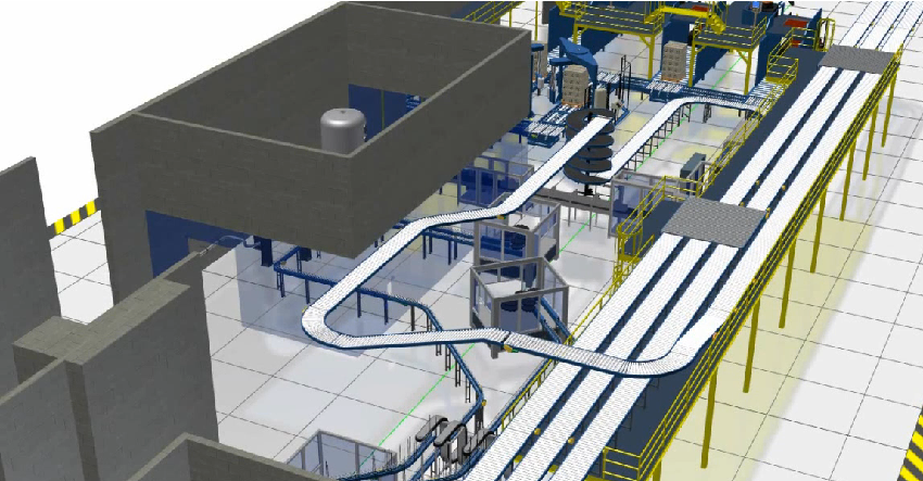
  2. 3D Modeling: With Autodesk Inventor, manufacturers can create 3D models of their factories, allowing them to visualize and optimize their designs before construction begins. This can help reduce costs and ensure that the factory meets all functional requirements.

  3. Building Design Optimization: AutoCAD Architecture provides a suite of powerful tools for building design optimization. This includes features such as automated documentation, advanced rendering, and collaboration tools, which can help manufacturers create optimized building designs.

  4. Factory Design and Simulation: Navisworks allows manufacturers to create detailed simulations of their factories, including machinery, equipment, and workflows. This can help identify potential issues before construction begins and ensure that the factory operates efficiently once it’s up and running.

factory design suite 2 Moving at the Speed of Business

Enhancing Factory Design with Navisworks and Factory Design Utilities

Navisworks and Factory Design Utilities are two key tools within the Product Design & Manufacturing Collection that can help manufacturers enhance their factory design process. Navisworks allows for detailed factory simulation, while Factory Design Utilities provides a suite of tools specifically designed for factory design.

Some of the key features of these tools include:

  1. Factory Design Utilities: This tool provides a suite of powerful tools specifically designed for factory design, including conveyor design, layout optimization, and factory equipment libraries.

  2. Navisworks: Navisworks allows manufacturers to create detailed simulations of their factories, including machinery, equipment, and workflows. This can help identify potential issues before construction begins and ensure that the factory operates efficiently once it’s up and running.

Factory Design Utilities AutoCAD Moving at the Speed of Business

Ready to Get Connected?

Save up to 20% on Autodesk Software and Services

Connecting the Tools for Seamless Factory Design

One of the key advantages of Autodesk’s Product Design & Manufacturing Collection is that it allows manufacturers to connect various tools within the suite to create a seamless factory design process. For example, manufacturers can use Navisworks to simulate their factory design, then use Factory Design Utilities to optimize the layout and equipment design, before using Inventor to create detailed 3D models of the factory.

Factory Design Utilities 1 Moving at the Speed of Business

Real-world Applications of Connected Factory Design

Connected factory design has numerous real-world applications across a wide range of industries. For example, automotive manufacturers can use these tools to design and build factories that are optimized for the production of electric vehicles. Pharmaceutical companies can use these

Top 5 Reasons to use Connected Factory Design with Product Design & Manufacturing Collection instead of only AutoCAD or Inventor

  1. Layout Optimization: One of the biggest advantages of using Factory Design Utilities is its ability to optimize the layout of a factory. This software enables users to create 3D factory models and simulate their operations, allowing them to test different layout configurations and optimize them for better productivity and efficiency.

  2. Equipment Design: Factory Design Utilities provides specialized tools for designing and placing factory equipment, including conveyors, robots, and other machinery. This software enables users to create accurate 3D models of equipment, test its functionality, and optimize its placement for maximum efficiency.

  3. Collaboration Tools: Factory Design Utilities also provides collaboration tools that allow multiple stakeholders to work on the same project simultaneously. This feature enables designers, engineers, and other team members to collaborate on designs, exchange feedback, and make changes in real-time, improving the overall quality of the design.

  4. Real-world Applications: Factory Design Utilities has been specifically designed for factory design and is widely used in real-world applications. This software has been used by manufacturers in various industries, including automotive, pharmaceutical, and consumer goods, to create efficient and effective factory designs.

  5. Time-to-Market: The use of Factory Design Utilities can help reduce the time-to-market of a product by enabling manufacturers to design and optimize their factories quickly and efficiently. This software allows manufacturers to test and optimize their designs before they are built, reducing the need for costly and time-consuming modifications during the construction phase.

Factory Design Utilities Commands

Command/ToolFactory Design UtilitiesAutoCADInventorNavisworks
LayoutFactory tab > Create Layout
Edit LayoutFactory tab > Edit Layout
Auto-RouteFactory tab > Auto-Route
Auto-PlaceFactory tab > Auto-Place
Factory ComponentsFactory tab > Factory Components
Insert DWG/DXFFactory tab > Insert DWG/DXF
Align and DistributeFactory tab > Align and DistributeModify tab > AlignAssemble tab > AlignModify tab > Align
Grounding and SurfaceFactory tab > Grounding and Surface
Place EquipmentFactory tab > Place Equipment
Factory AssetsFactory tab > Factory AssetsNavisworks Manage tab > Manage Assets
Assets from InventorFactory tab > Assets from InventorNavisworks Manage tab > Import Inventor
Asset PropertiesFactory tab > Asset PropertiesNavisworks Manage tab > Asset Properties
VisualizeFactory tab > VisualizeVisualize tab > RenderStudio tab > Create Studio RenderNavisworks Manage tab > Visualize
AnalyzeFactory tab > AnalyzeNavisworks Manage tab > Analyze
OptimizeFactory tab > OptimizeNavisworks Manage tab > Optimize
Sync to FactoryFactory tab > Sync to FactoryNavisworks Manage tab > Synchronize
Add to Factory AssetsFactory tab > Add to Factory AssetsNavisworks Manage tab > Add to Assets
Update from Factory AssetsFactory tab > Update from Factory AssetsNavisworks Manage tab > Update from Assets
Factory ReportsFactory tab > Factory ReportsNavisworks Manage tab > Report

Case Studies

Here are some case studies for Autodesk Factory Design Utilities and Factory Design Suite:

  1. FLSmidth: FLSmidth, a global supplier of cement and minerals processing equipment, used Autodesk Factory Design Suite to design and optimize a new manufacturing facility in China. The software allowed them to create a 3D model of the plant layout and simulate different scenarios to identify the most efficient design.

  2. Pratt & Whitney: Pratt & Whitney, a manufacturer of aircraft engines, used Autodesk Factory Design Suite to design a new production facility in Singapore. The software allowed them to visualize the facility in 3D and optimize the layout to reduce material handling and increase efficiency.

  3. Hekuma: Hekuma, a manufacturer of injection molding systems, used Autodesk Factory Design Suite to design a new factory in Germany. The software allowed them to create a 3D model of the facility and simulate different scenarios to optimize the layout for efficiency and safety.

  4. Sandvik Mining: Sandvik Mining, a global supplier of mining equipment and services, used Autodesk Factory Design Suite to design a new manufacturing facility in South Africa. The software allowed them to visualize the layout in 3D and optimize the design to reduce material handling and increase productivity.

  5. The Heinz Endowments: The Heinz Endowments, a nonprofit organization focused on environmental sustainability, used Autodesk Factory Design Utilities to design a new sustainable manufacturing facility in Pittsburgh. The software allowed them to create a 3D model of the facility and simulate different scenarios to optimize the design for energy efficiency and sustainability.

These case studies demonstrate the diverse range of industries and applications for Autodesk Factory Design Utilities and Factory Design Suite, and the software’s ability to improve efficiency, productivity, and sustainability in manufacturing and production facilities.

Ready to get your Factory Design Connected?

Discover how Autodesk Product Design & Manufacturing Collection can streamline your workflow, increase productivity, and optimise your design process. 

Get up to 20% Off Software or Services!

Contact us to find out how much money you can save on software, training or other services. Fill out the form below, by live chat, phone or email.

P: 1800 490 514 |  E: info@designconsulting.com.au

Connected Design

Connected Factory Design Moving at the Speed of Business

Connected Design with Product Design & Manufacturing Collection

Click a link below to learn more about Connected Design using the Autodesk Product Design & Manufacturing Collection 

VIEW MORE