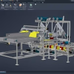
Inventor CAM and Nesting
Inventor CAM and Nesting Software
A set of integrated fabrication tools for Inventor Professional found within the Product Design & Manufacturing Collection
Inventor CAM
Autodesk® Inventor® CAM software is included in the Product Design & Manufacturing Collection and integrated within Inventor Professional for 2.5-axis to 5-axis milling, turning, and mill-turn machining.
- Advanced roughing system that efficiently removes high material volumes which minimises your CNC machines wear and tear on tooling
- Generates G-Code for CNC Machines
4- and 5-axis milling
Simultaneous 4- and 5-axis features for machining complex models include tilt, multi-axis contour, and swarf.
Turning and mill-turn
Improve productivity with traditional turning, facing, grooving, and boring functions. Includes support for live tooling mill-turning.
Inventor CAM Features and Functions
Drill Toolpaths
These are the types of drilling motion that can be performed:
- Drilling – G81 style drilling with rapid out.
- Counterboring – G82 style drilling with dwell at bottom and rapid out.
- Chip breaking – Chip breaking with pecking and partial retracts between pecks.
- Deep drilling – Deep drilling with pecking and full retract between pecks.
- Guided deep drilling – gun drilling – Deep drilling that produces a very round hole with a precision diameter. Very useful for deep, straight holes in a variety of materials.
- Tapping – Tapping (G84/G74). Synchronous spindle speed and feed.
- Tapping with chip breaking – Tapping with chip breaking.
- Break through – Allows for reduced feed and speed before breaking through a hole.
- Reaming – Reaming (G85 style) with feed out.
- Boring – Boring with dwell at bottom and feed out.
- Stop boring – Boring (G86 style) with spindle stop at the bottom and rapid out.
- Fine boring – Fine boring with shift away from the hole side.
- Back-boring – Boring from the back.
- Circular pocket milling – Circular pocket milling.
- Bore milling – Bore milling.
- Thread milling – Thread milling.
- Probe – Used to measure a feature on the part with a probe tool, or use macros from the machine to define the WCS. Needs special handling in the post processors depending on the machine.
Coolant
Select the type of coolant used with the machine tool. Not all types will work with all machine postprocessors.

Feed & Speed
Spindle and Feedrate cutting parameters.
- Spindle Speed – The rotational speed of the spindle expressed in Rotations Per Minute (RPM)
- Surface Speed – The speed which the material moves past the cutting edge of the tool (SFM or m/min)
- Plunge Feedrate – The drilling feedrate when plunging into stock
- Feed per Revolution – The plunge feedrate expressed as the feed per revolution
- Retract Feedrate – Feed used when retracting, but not using rapid moves (G0)

3D Milling

Probing Cycle Reference
- Single axis probing
- Corner probing
- Block center probing
- Rectangular cavity center probing
- Circular boss center probing
- Circular hole center probing
- Rectangular and Circular cavity with Islands
- Between 2 walls/faces
- Single axis probing
- Corner probing
- Block center probing
- Rectangular cavity center probing
- Circular boss center probing
- Circular hole center probing
- Rectangular and Circular cavity with Islands
- Between 2 walls/faces
Inventor Nesting
Inventor® Nesting software which is integrated within Inventor Professional turns sheet metal parts into nesting tables.
By optimising the nest table, companies reduce raw material costs and can compare nesting studies to better understand cost and choose the right nesting study.
Have multiple material and packaging options by generating multiple sheet nests in a single study
Maximise job profitability by comparing costs and the efficiency associated with nesting studies variations.
Ensure consistent grain direction on all parts to prevent cracking in subsequent bending operations by specifying allowable orientations.

Automated true-shape nesting
Generate multiple sheet nests to reduce raw material waste. Optimize the use of materials in flat cutting operations.
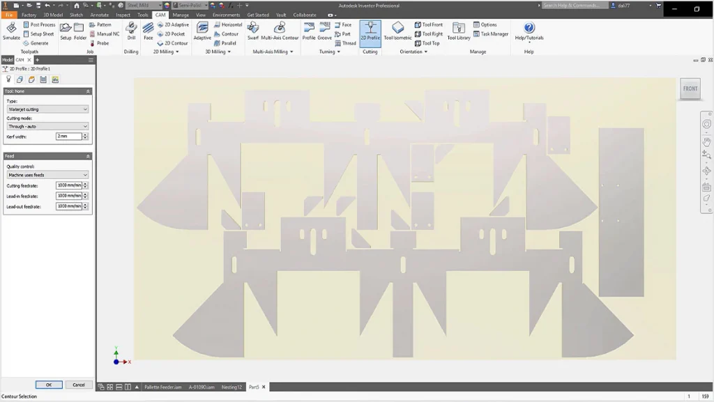
Smooth workflows for creating cutting paths
Create 3D models of a nest and generate cutting paths with Inventor CAM, or export DXF files. Use DXF files in AutoCAD and other toolpath-making software.
Inventor Nesting Features and Functions
- Supports Inventor ipt, iam and AutoCAD dwg or dxf files.
- Setup Nest and Quantities
- Set Up Shapes
- Set Up Packaging
- Adjust Parameters and Performance
- Create the Nesting Study
- Calculate Nests
- Compare Nests
- Change Shape Priority and Orientation
- Edit Shape Properties
- Nest Reports
- Generate a 3D Model
- Import and Export Data to CSV or XML
- Process Material Library
- Set Nesting Parameters
- Set Composite Properties

PDM Collection Add-Ons
Check out these programs and plug-ins to boost productivity even further.
Contact Us
If you would like to learn more about Autodesk Product Design & Manufacturing Collection, please contact us by calling on 1800 490 514, by filling out the form or clicking the live chat in the bottom right-hand corner.


