1800 490 514 [email protected]

Autodesk Plant 3D vs Inventor: A Comprehensive Overview of DWG Workflows and Differences
autodesk inventor vs advance steel

Autodesk Plant 3D vs Inventor: A Comprehensive Overview of DWG Workflows and Differences

Autodesk Plant 3D vs Inventor

When it comes to CAD software, Autodesk offers a range of powerful tools tailored to specific industries. Two of the most popular among these are Autodesk Inventor and Plant 3D. Understanding the differences between these applications and their respective workflows is essential for professionals aiming to maximise their design efficiency.

This post provides a detailed comparison of Autodesk Inventor and Plant 3D, including a table that highlights their key differences, along with an in-depth analysis of their functionalities, workflows, and interoperability with other Autodesk tools.

Overview of Each Software

  • Inventor: Optimised for Small-Scale Mechanical Systems

Autodesk Inventor is ideal for projects involving detailed mechanical parts, assemblies, and compact systems. Its parametric 3D modelling capabilities allow engineers to create precise mechanical designs with intricate detail. The software’s tube and piping module is specifically designed for smaller piping projects, such as systems that can fit on the back of a truck.

However, while Inventor excels at mechanical design, it lacks built-in tools for process-specific tasks like P&ID creation. For projects that involve piping and instrumentation diagrams, users must create P&IDs manually, which can slow down the design process for larger, more complex systems.

  • Plant 3D: Designed for Large-Scale Process Plants

Autodesk Plant 3D is built for large, interconnected systems, particularly in industries like oil and gas, chemical processing, and water treatment. With its integrated AutoCAD P&ID tool, Plant 3D allows users to create P&IDs directly within the software. These P&IDs can be linked to 3D models, ensuring that any changes are reflected across the entire design, making the process more efficient and reducing the risk of errors.

Plant 3D also excels in plant-wide piping systems and isometric drawing generation essential for large-scale projects involving extensive piping runs and standardised equipment.

Key Differences Between Inventor and Plant 3D

The following table summarises the primary differences between Autodesk Inventor and Plant 3D:

FeatureAutodesk InventorAutodesk Plant 3D
Project SizeSmall mechanical systemsLarge plants, long pipe runs, extensive equipment layouts
Piping SystemsTube and Piping module for small-scale designsComprehensive plant-wide piping systems
P&ID IntegrationP&IDs must be created manuallyAutoCAD P&ID integrated, linked to 3D models
3D Equipment ModellingMechanical parts and compact assembliesPlant-scale equipment and piping systems
InteroperabilityExport 3D equipment to DWG, integrate with VaultSeamless catalogue management, isometrics generation
Collaboration ToolsAutodesk Vault for version controlIntegrated project management and collaboration tools
Isometric DrawingsNot natively supportedAutomatic generation from 3D models
Material ManagementFocused on mechanical parts and assembliesBOM for piping and equipment management
User InterfaceAdvanced 3D modelling environmentIntuitive interface for process design

DWG Workflows in Inventor and Plant 3D

DWG Workflows in Inventor:
  • File Creation: Users create 3D models in Inventor, which can be saved as DWG files for further editing in AutoCAD or for sharing with other stakeholders. This interoperability ensures that designs can be easily communicated and modified.
  • 2D Drawings: Inventor allows users to generate detailed 2D drawings from 3D models, ensuring that all views, dimensions, and annotations are accurately represented in DWG format. This feature is crucial for manufacturing processes where precise specifications are required.
  • Collaboration: The ability to export DWG files promotes collaboration with professionals who may not have access to Inventor but work within AutoCAD. This flexibility allows teams to work more efficiently, leveraging the strengths of each software.
DWG Workflows in Plant 3D:
  • P&ID Development: Plant 3D users can create P&IDs, which are saved as DWG files, serving as the blueprint for piping and instrumentation layouts. This foundational step is essential for any plant design project, as it establishes the functional layout of systems.
  • 3D Model Generation: The software allows users to create 3D models of piping systems and equipment that can be directly generated in DWG format. This feature streamlines the process of documentation and sharing, ensuring that all team members have access to the most up-to-date designs.
  • Isometric Drawings: Plant 3D supports the automatic generation of isometric drawings from 3D models, which are essential for piping layouts. This capability not only saves time but also reduces errors that can occur when manually creating these drawings.

Interoperability With Advance Steel and AutoCAD

Both Autodesk Plant 3D and Inventor offer interoperability with Advance Steel and AutoCAD, enhancing their usability across different engineering disciplines.

  • Advance Steel: While primarily for structural detailing, Advance Steel can take advantage of models created in Inventor and layouts from Plant 3D. This interoperability is beneficial for projects that require mechanical and structural components, enabling seamless integration of designs.
  • AutoCAD: As the foundational software, AutoCAD serves as a common platform for DWG files. Both Inventor and Plant 3D can export to and import from AutoCAD, allowing seamless collaboration across various teams. This interoperability ensures that design updates are easily shared and implemented, promoting efficiency in the overall workflow.

Integrating Inventor with Plant 3D: The Power of BIM

For projects that require mechanical equipment design and plant-wide piping systems, Autodesk provides a robust solution through BIM content publishing tools. With these tools, engineers can design 3D equipment in Inventor and seamlessly integrate that content into Plant 3D.

This integration is particularly valuable for professionals working on multidisciplinary projects. For example, custom-designed mechanical equipment created in Inventor can be published as BIM content and incorporated into the Plant 3D catalogue ensuring consistency and eliminating the need for rework between platforms.

Real-world Applications

Understanding the differences between Autodesk Plant 3D and Inventor also involves examining their applications in real-world scenarios.

  1. Manufacturing and product design: In industries such as automotive and aerospace, Autodesk Inventor is widely used to design mechanical components. Engineers leverage their parametric modelling capabilities to create complex assemblies, conduct simulations, and manage changes efficiently. The ability to export detailed 2D drawings in DWG format allows for effective communication with manufacturing teams.
  2. Process Plant Design: For industries like oil and gas, water treatment, and chemical processing, Autodesk Plant 3D is the go-to solution. The ability to create detailed P&IDs, generate 3D models of piping systems, and automatically produce isometric drawings streamlines the design process. Collaboration tools enable multidisciplinary teams to work cohesively, ensuring that every aspect of the plant design is accounted for.

Experience the Difference Between Autodesk Plant 3D and Inventor

Both Autodesk Inventor and Plant 3D are powerful tools, each designed for specific industries and applications. Inventor excels in mechanical design and manufacturing, while Plant 3D focuses on process and plant design. The choice between these two software options largely depends on the industry, project requirements, and desired workflows.

Understanding the differences in their DWG workflows, interoperability with other Autodesk products, and unique features is crucial for professionals aiming to enhance their design processes. By leveraging the strengths of each application, users can ensure that their designs are efficient, accurate, and tailored to their specific needs. Whether you are involved in mechanical design or plant engineering, choosing the right software is essential for success in today’s competitive landscape.

Get the best prices on Autodesk software.

Get skilled up and enroll in an Autodesk training course

Setup, libraries, programming and consulting services

Contact Us

Contact us to find out how we can help your business. Fill out the form below, by live chat, phone or email.

P: 1800 490 514 |  E: [email protected]

Connected Design

Design Consulting Autodesk Gold Partner
about design consulting Moving at the Speed of Business

VIEW MORE

Autodesk Inventor vs. Advance Steel: A Detailed Comparison

autodesk inventor vs advance steel

Autodesk Inventor vs. Advance Steel: A Detailed Comparison

autodesk inventor vs advance steel

Choosing the right design software can make or break a project, especially when you’re dealing with complex structures or intricate mechanical systems. If you’re in the engineering or construction world, you’ve likely heard the debate about Autodesk Inventor vs Advance Steel—two industry-leading tools, each designed to tackle different challenges.

In this comprehensive comparison, we’ll explore the strengths of both software packages, breaking down their features and applications so you can make an informed decision. Whether you’re building next-generation machinery or detailing a steel structure for a high-rise building, understanding these tools’ capabilities will ensure you’re leveraging the best technology for your needs.

So, if you’re ready to elevate your engineering or construction projects, let’s dive into the intricate details that set Autodesk Inventor vs Advance Steel apart. Buckle up—this deep dive will give you the insights you need to choose wisely and maximise efficiency, accuracy, and innovation in your next project.

Overview of Autodesk Inventor

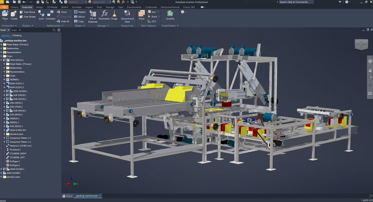
Autodesk Inventor is a comprehensive 3D CAD software primarily used for mechanical design. It supports a wide range of applications, from product design to manufacturing, enabling engineers to create highly detailed models, prototypes, and documentation.

Key Features of Autodesk Inventor for Steel Design and Fabrication
  • Parametric Modelling: Inventor’s parametric design capabilities allow engineers to define and manipulate relationships between elements, facilitating easy updates and modifications throughout the design process.
  • Frame Generator: This tool simplifies the creation of structural frames. Users can quickly generate accurate frame designs using pre-configured components, which is particularly useful in fabricating steel structures. Frame Generator: This tool simplifies the creation of structural frames. Users can quickly generate accurate frame designs using pre-configured components, which is particularly useful in fabricating steel structures. However, Inventor’s Frame Generator lacks the advanced editing and automation functions that Advance Steel offers for creating connections, cuts, trims, notches, and more.
  • Large Content Library: Inventor includes an extensive library of components such as fasteners, structural shapes, and other mechanical parts, enabling efficient design workflows without the need to create standard components from scratch.
  • Integrated Simulation: Engineers can run simulations directly within Inventor to assess stress, motion, and deflection. This feature helps optimise designs before manufacturing, reducing the need for physical prototypes.
  • Sheet Metal Design: Both Inventor and Advanced Steel have sheet metal tools. In Inventor the module is called Sheet Metal and in Advance Steel, it’s referred to as Folded Plate.
  • Automated Documentation: Using the integration with the iLogic design automation programming environment, you can automate manufacturing drawings, complete with dimensions, annotations, and BOMs (Bills of Materials), ensuring consistency and reducing manual errors.
Ideal Use Cases for Autodesk Inventor
  • Architectural Fabrication: Inventor has the flexible 3D modelling tools to design fabricated products that are aesthetic, ergonoic or organic in design, where as Advance Steel is better suited for straight lines and industrial projects.
  • Mechanical Engineering: Inventor is well-suited for designing mechanical systems and components that require precision and the ability to simulate real-world performance.
  • Product Development: Its comprehensive toolset allows for detailed product design, from concept to final prototype.
  • Structural Fabrication: Although primarily a mechanical tool, Inventor can handle structural steel design, making it versatile for mixed mechanical and structural projects.

Overview of Advance Steel

Advance Steel is a specialised software focused on structural steel detailing. It integrates seamlessly with BIM (Building Information Modelling) workflows, providing tools for automating the creation of detailed fabrication drawings, models, and documentation required for steel construction.

Key Features of Advance Steel
  • Specialised Steel Detailing Tools: Advance Steel is purpose-built for structural detailing, offering tools that cater specifically to the needs of steel fabricators and structural engineers. These tools include advanced steel editing and automation functions for making cuts, trims, and notches.
  • Automatic Fabrication Drawings: The software can automatically generate comprehensive fabrication drawings, reducing the time from design to production and ensuring all structural elements are accurately detailed.
  • Connection Libraries: Advance Steel includes a vast library of pre-configured steel connections, making it easier to apply standardised joints in structural designs. Users can also create custom connections to meet specific project requirements. Inventor, on the other hand, lacks this advanced parametric connection library.
  • BIM integration: Advance Steel syncs seamlessly with Revit, while Inventor also offers BIM integration, including the ability to export to Revit as RVT or RFA files.
  • Efficient Material Management: The software automates the generation of BOMs, cut lists, and material takeoffs, streamlining the process of inventory management and cost estimation in construction projects.
  • Advanced Documentation and Revision Control: Advance Steel’s documentation features are tightly integrated with the model, ensuring that changes to the design automatically update all associated drawings and documentation.
Ideal Use Cases for Advance Steel
  • Structural Engineering: Advance Steel is ideal for engineers who focus on the design, detailing, and documentation of steel structures.
  • Steel Fabrication: The software’s automation capabilities make it invaluable for fabricators who require precise and efficient production workflows.
  • Construction Projects: Its BIM integration and detailed documentation support complex construction projects involving structural steel.

Feature Comparison of Overlapping Tools

Both Autodesk Inventor and Advance Steel offer tools that overlap in the realm of metal design, particularly in frame generation and sheet metal design. Here’s a detailed comparison of these features:

Frame Generation and Steel Editing
  • Autodesk Inventor Frame Generator:
    • Allows users to create structural frames quickly using predefined components.
    • Supports basic bolted connections and weldments.
    • Limitations: Lacks connection library and advanced editing capabilities and automation for cuts, trims, and notches compared to Advance Steel.
  • Advance Steel Steel Editing:
    • Offers advanced tools for creating and modifying steel structures, including automated functions for cuts, trims, and notches.
    • Includes a parametric connection library that automatically adjusts connection sizes based on member dimensions.
    • Strengths: Provides comprehensive tools for stairs, rails, and portal buildings, which Inventor does not offer.
Sheet Metal Design
  • Inventor Sheet Metal Design:
    • Provides tools for creating and manipulating sheet metal parts, including folding and cutting.
    • Applications: Ideal for industries requiring detailed sheet metal fabrication.
Automation and Documentation
  • Inventor Automation:
    • Has a 2D/3D automation for drawing environments and exporting DXF files.
    • Complexity: 3D automation and basic 2D automation are relatively easy, fully automating part drawings can be complex
  • Advance Steel Automation:
    • Provides robust automation for part drawings, DXF files for laser/plasma cutters, and NC1 G-code for beamline machines.
    • Efficiency: Streamlines the documentation process, making it faster and more reliable.

Autodesk Inventor vs Advance Steel: Key Differences


FeatureAutodesk InventorAdvance Steel
Focus3D Mechanical DesignStructural Steel Detailing
Primary ApplicationProduct Development, Mechanical Systems, FabricationSteel Structures, Construction Projects
IndustryProduct Design, Industrial MachineryConstruction, Structural Engineering
Modelling CapabilitiesParametric Mechanical ComponentsDetailed Steel Structures and Connections
Simulation ToolsIntegrated for Mechanical PartsNone. Need to export to Robot or other FEA packages
BIM SupportNo bidirectional Sync tool with Revit but offers many sync workflows and import/export capabilitiesSyncs with Revit and Robot structural analysis
DocumentationAutomated Manufacturing DrawingsAutomated Fabrication Drawings
Steel Editing ToolsFrame GeneratorAdvanced Steel Editing and Automation
Connection LibrariesLimitedVast Parametric Connection Library
Specialised ToolsSheet Metal DesignFolded Plates, Stairs, Rails, Portal Buildings
Drawing AutomationComplex to set upAutomated through a Dedicated Tool
Fabrication AutomationDXF ExportDXF, NC1(G-Code Export)

Autodesk Inventor vs Advance Steel: Choosing the Right Tool for Your Needs

When to Use Autodesk Inventor

Inventor is the optimal choice for projects that require detailed mechanical design, particularly in industries like automotive, aerospace, and product development. It provides the necessary tools for creating, testing, and refining mechanical parts and assemblies, making it ideal for engineers who need to model complex components and simulate their behaviour under various conditions. In addition to its robust design capabilities, Inventor excels in modeling complex shapes with curvature, making it especially useful for designs that require intricate and organic geometries. Its frame generator and sheet metal design tools can also be beneficial for certain structural steel projects.

When to Use Advance Steel

Advance Steel is the go-to software for professionals in structural engineering and steel fabrication. Its specialised tools and BIM integration make it essential for efficiently detailing and documenting steel structures in construction projects. It is particularly beneficial for fabricators who need to automate drawing production and ensure compliance with industry standards. Advance Steel’s advanced steel editing tools, parametric connection library, and specialised features like folded plate, stairs, rails, and portal buildings make it the superior choice for complex structural steel projects. However, while Advance Steel excels in structural steel detailing, it may not be the best option for projects involving curved shapes. 

This means that for architectural applications requiring curvature, Inventor is the better tool, whereas, for industrial applications, Advance Steel proves to be the superior choice.

Autodesk Inventor and Advance Steel integration

While both tools are better at certain tasks, you can still integrate both tools and combine their tool sets to create more detailed designs. Here’s how it works.

Steps to Convert IFC Components into Advance Steel Members:
    1. Import the IFC File:
      Use the Import function in Advance Steel to bring the IFC file into your project.
      Go to Home > Import > IFC and select the IFC file.
      The IFC components will be imported into Advance Steel as 3D solids, and they won’t initially be recognized as standard Advance Steel members like beams or columns.
    2. Inspect the Imported Geometry:
      After importing the IFC file, inspect the components to understand the structural elements (e.g., beams, columns, plates) that need to be converted into Advance Steel members.
      Use the Object Inspector or Properties panel to check the dimensions and placement of each component.
    3. Convert Geometry to Advance Steel Objects:
      To convert IFC objects (such as solids) into parametric Advance Steel members, you can use the “Convert to Advance Steel Object” feature:
      • Beams and Columns: For linear objects that represent beams or columns, you can use the Beam Conversion Tool to convert them into standard Advance Steel beams.
        Use the “Advance Steel Beams” command to recreate the IFC solid as a native Advance Steel beam. This will allow you to assign profiles and cross-sections, as well as work with connections and detailing tools.
      • Plates: If the IFC model contains plates or sheet elements, you can convert these into Advance Steel plates using the Plate Tool. This lets you add cuts, bolts, and welding details.
    1. Assign Structural Properties:
      After converting the geometry to Advance Steel members, assign the appropriate material, section type, and structural properties to each member.
      You can also apply Advance Steel’s intelligent connections (e.g., bolt groups, welds, stiffeners) to the converted members.
    2. Refine the Model:
      Depending on the complexity of the IFC import, some components might require further manual adjustments or reconstruction to align with Advance Steel’s parametric modeling system.
      For example, custom connection types from IFC may need to be rebuilt using Advance Steel’s native tools for connections.
    3. Save the Converted Model:
      Once the conversion is complete, save the model as an Advance Steel project. You can now take advantage of Advance Steel’s automated detailing, fabrication drawings, and BOM generation features for your newly converted members.

Unlock Your Design Potential—Choose the Right Tool for Success

Autodesk Inventor vs Advance Steel is a debate that is likely to continue, given how powerful both tools are. Inventor excels in mechanical design and product development, offering robust simulation and modelling capabilities. Advance Steel, on the other hand, is unparalleled in its ability to streamline structural steel detailing and integrate seamlessly with BIM workflows.

So, based on your requirements and the demands of the projects you’re working on, make sure to choose the right product that will help you deliver great results. If your focus is on mechanical design and product development, Inventor is the clear choice. But if you’re working on complex structural steel projects that require advanced detailing, automation, and BIM integration, Advance Steel is the superior option.

Get the best prices on Autodesk software.

Get skilled up and enroll in an Autodesk training course

Setup, libraries, programming and consulting services

Contact Us

Contact us to find out how we can help your business. Fill out the form below, by live chat, phone or email.

P: 1800 490 514 |  E: [email protected]

Connected Design

Design Consulting Autodesk Gold Partner
about design consulting Moving at the Speed of Business

VIEW MORE

Marvellous Mechanical Drafting with Autodesk AutoCAD Mechanical

Autodesk AutoCAD Mechanical

Marvellous Mechanical Drafting with Autodesk AutoCAD Mechanical

Autodesk AutoCAD Mechanical

Did you know that the global CAD software market was valued at $9.3 billion in 2019 and is projected to grow at a rate of 6.6% annually, reaching $18.7 billion by 2030? This growth is driven by the increasing complexity of design requirements and the need for more efficient and accurate tools in industries like manufacturing and automotive.

In this environment, what if you could cut your design time nearly in half while simultaneously reducing errors and enhancing the quality of your work? This is not just a dream but a reality with Autodesk AutoCAD Mechanical, a specialised toolset within AutoCAD that is revolutionising the field of mechanical drafting.

AutoCAD Mechanical is not just another CAD software; it’s a comprehensive solution tailored specifically for mechanical engineering. It combines the robust capabilities of AutoCAD with libraries of standards-based parts and tools designed to automate common mechanical CAD tasks. This powerful combination allows engineers and designers to save countless hours on design and rework, freeing them to focus on innovation and problem-solving.

In this blog post, we’ll explore the marvels of mechanical drafting with AutoCAD Mechanical, delving into its features, benefits, and the impressive productivity gains it offers.

Productivity Gains with Autodesk AutoCAD Mechanical

A productivity study commissioned by Autodesk highlighted the significant time savings and efficiency improvements offered by the Mechanical toolset in AutoCAD. The study compared the time required to complete various design tasks using Autodesk AutoCAD Mechanical vs AutoCAD

Here are some key findings from the study: 

  • Faster Design and Rework: The Mechanical toolset reduces the total time required for 2D CAD work by approximately 55%. This is achieved through automation and the availability of standardised parts and functions.
  • Reduced Risk of Errors: Standardised functions and parts not only speed up the design process but significantly reduce the risk of errors. This leads to higher accuracy and consistency in designs.
  • Enhanced Efficiency: Common design tasks, such as searching for project data, inserting standard and supplier parts, and structuring data, are all streamlined with the Mechanical toolset. This efficiency frees up valuable time for more critical aspects of design.
Advantages of Using Autodesk AutoCAD Mechanical
Autodesk AutoCAD Mechanical

AutoCAD Mechanical offers numerous advantages that significantly enhance the efficiency and effectiveness of mechanical drafting. Here are some key benefits:

  1. Intelligent Layer Management: The Mechanical toolset in AutoCAD simplifies the task of managing layers by automatically placing items on the correct layer, colour, and linetype as you create your drawing. This system can be easily customised based on your company’s requirements, ensuring consistency and accuracy in your designs. Customisable layer types include text and hatching, centerlines and construction lines, hidden lines, symbols and notes, and title borders.
  2. Time Savings and Efficiency: AutoCAD Mechanical substantially reduces the time required to complete various tasks. For instance, preparing existing data, creating new concepts, and structuring data are significantly faster with the Mechanical toolset, resulting in up to 45% time savings. Similarly, tasks such as detailing and optimising new designs, calculating forces, and modifying parts are completed much quicker compared to basic AutoCAD, often saving up to 80% of the time.
  3. Enhanced Calculation Functions: The toolset offers robust calculation functions, allowing users to perform analysis on 2D geometry subject to static loads. This includes calculating stress and deformation in a plane or cross-section with individual forces and stretching loads. These capabilities are crucial for ensuring the structural integrity and performance of mechanical parts.
  4. Automated Updates and Synchronisation: The Mechanical toolset ensures that any change made to a component automatically updates all related components. This feature is particularly beneficial in complex assemblies where changes to one part must be reflected across the entire design. This automation reduces the likelihood of errors and ensures that all parts of the design remain consistent.
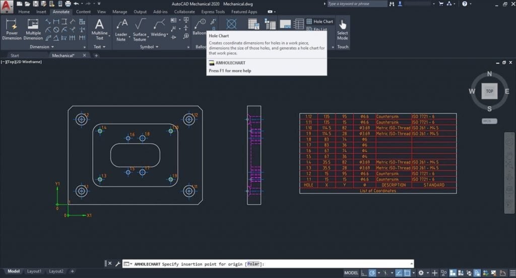
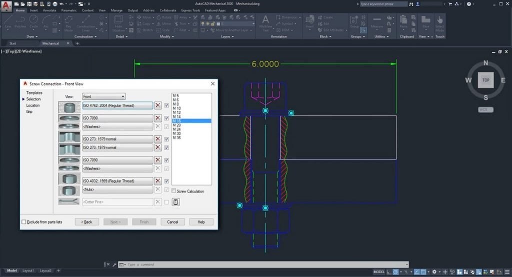
  5. Comprehensive Standard Parts Library:  Autodesk AutoCAD Mechanical includes a vast library of over 100,000 pre-drawn standard features such as undercuts, keyways, and thread ends, and more than 8,000 pre-drawn holes including through holes, blind holes, counterbored holes, countersunk holes, and oblong holes. These features automatically clean up the insertion area in the drawing, eliminating the need for manual editing and significantly speeding up the design process.
  6. Efficient Production Drawing Creation: The toolset makes creating production drawings for parts and assemblies much more efficient. Automated and associative parts lists and bills of materials (BOMs) update automatically as the design changes. This ensures that all documentation is up-to-date and accurate, facilitating smoother transitions to manufacturing and reducing production delays.
  7. Power Commands: AutoCAD Mechanical’s Power Commands utilise object information to accelerate user operations such as editing and copying objects. This feature allows users to bypass traditional pull-down menus, toolbars, and tablet locations, using the objects themselves as command menus. This intuitive interface streamlines the design process and enhances productivity.
  8. Specialised Drafting Tools: The toolset includes over 30 options for rectangle, arc, and circle creation, nearly automatic centerline creation and updating, speciality lines for breakout views and section lines, and a full suite of construction lines for aligning drafting views. These specialised tools are designed specifically for mechanical drafting, providing more precise and efficient ways to create detailed and accurate drawings.
  9. Foreground/Background Management: AutoCAD Mechanical simplifies the management of foreground and background elements in a drawing. It automatically redraws geometry to show hidden or dashed lines of parts obstructed by other parts in a design. Hidden lines update automatically when changes occur, eliminating the need for manual redrawing due to design changes. This feature ensures that designs are always clear and accurate, reducing the time and effort required to update 2D designs.

These advantages make Autodesk AutoCAD Mechanical an indispensable tool for mechanical engineers and designers, enabling them to produce high-quality, precise, and efficient designs with less effort and in less time. Whether you’re working on simple components or complex assemblies, the Mechanical toolset offers the functionality and flexibility needed to meet the demands of modern mechanical design.

Embrace the Future of Mechanical Drafting with Autodesk AutoCAD Mechanical

Autodesk AutoCAD Mechanical is a powerful toolset that revolutionises mechanical drafting by enhancing productivity, reducing errors, and automating routine tasks. Whether you’re designing complex machinery, optimising existing designs, or calculating forces in a mechanism, AutoCAD Mechanical provides the tools and features you need to work more efficiently and accurately.

By incorporating AutoCAD Mechanical into your workflow, you can significantly cut down on design and rework time, allowing you to focus on innovation and quality. Embrace the marvels of mechanical drafting with AutoCAD Mechanical and take your engineering projects to new heights.

Contact Us

Contact us to find out how we can help your business. Fill out the form below, by live chat, phone or email.

P: 1800 490 514 |  E: [email protected]

Connected Design

Design Consulting Autodesk Gold Partner
about design consulting Moving at the Speed of Business

VIEW MORE