1800 490 514 [email protected]

Marvellous Mechanical Drafting with Autodesk AutoCAD Mechanical
Autodesk AutoCAD Mechanical

Marvellous Mechanical Drafting with Autodesk AutoCAD Mechanical

Autodesk AutoCAD Mechanical

Did you know that the global CAD software market was valued at $9.3 billion in 2019 and is projected to grow at a rate of 6.6% annually, reaching $18.7 billion by 2030? This growth is driven by the increasing complexity of design requirements and the need for more efficient and accurate tools in industries like manufacturing and automotive.

In this environment, what if you could cut your design time nearly in half while simultaneously reducing errors and enhancing the quality of your work? This is not just a dream but a reality with Autodesk AutoCAD Mechanical, a specialised toolset within AutoCAD that is revolutionising the field of mechanical drafting.

AutoCAD Mechanical is not just another CAD software; it’s a comprehensive solution tailored specifically for mechanical engineering. It combines the robust capabilities of AutoCAD with libraries of standards-based parts and tools designed to automate common mechanical CAD tasks. This powerful combination allows engineers and designers to save countless hours on design and rework, freeing them to focus on innovation and problem-solving.

In this blog post, we’ll explore the marvels of mechanical drafting with AutoCAD Mechanical, delving into its features, benefits, and the impressive productivity gains it offers.

Productivity Gains with Autodesk AutoCAD Mechanical

A productivity study commissioned by Autodesk highlighted the significant time savings and efficiency improvements offered by the Mechanical toolset in AutoCAD. The study compared the time required to complete various design tasks using Autodesk AutoCAD Mechanical vs AutoCAD

Here are some key findings from the study: 

  • Faster Design and Rework: The Mechanical toolset reduces the total time required for 2D CAD work by approximately 55%. This is achieved through automation and the availability of standardised parts and functions.
  • Reduced Risk of Errors: Standardised functions and parts not only speed up the design process but significantly reduce the risk of errors. This leads to higher accuracy and consistency in designs.
  • Enhanced Efficiency: Common design tasks, such as searching for project data, inserting standard and supplier parts, and structuring data, are all streamlined with the Mechanical toolset. This efficiency frees up valuable time for more critical aspects of design.
Advantages of Using Autodesk AutoCAD Mechanical
Autodesk AutoCAD Mechanical

AutoCAD Mechanical offers numerous advantages that significantly enhance the efficiency and effectiveness of mechanical drafting. Here are some key benefits:

  1. Intelligent Layer Management: The Mechanical toolset in AutoCAD simplifies the task of managing layers by automatically placing items on the correct layer, colour, and linetype as you create your drawing. This system can be easily customised based on your company’s requirements, ensuring consistency and accuracy in your designs. Customisable layer types include text and hatching, centerlines and construction lines, hidden lines, symbols and notes, and title borders.
  2. Time Savings and Efficiency: AutoCAD Mechanical substantially reduces the time required to complete various tasks. For instance, preparing existing data, creating new concepts, and structuring data are significantly faster with the Mechanical toolset, resulting in up to 45% time savings. Similarly, tasks such as detailing and optimising new designs, calculating forces, and modifying parts are completed much quicker compared to basic AutoCAD, often saving up to 80% of the time.
  3. Enhanced Calculation Functions: The toolset offers robust calculation functions, allowing users to perform analysis on 2D geometry subject to static loads. This includes calculating stress and deformation in a plane or cross-section with individual forces and stretching loads. These capabilities are crucial for ensuring the structural integrity and performance of mechanical parts.
  4. Automated Updates and Synchronisation: The Mechanical toolset ensures that any change made to a component automatically updates all related components. This feature is particularly beneficial in complex assemblies where changes to one part must be reflected across the entire design. This automation reduces the likelihood of errors and ensures that all parts of the design remain consistent.
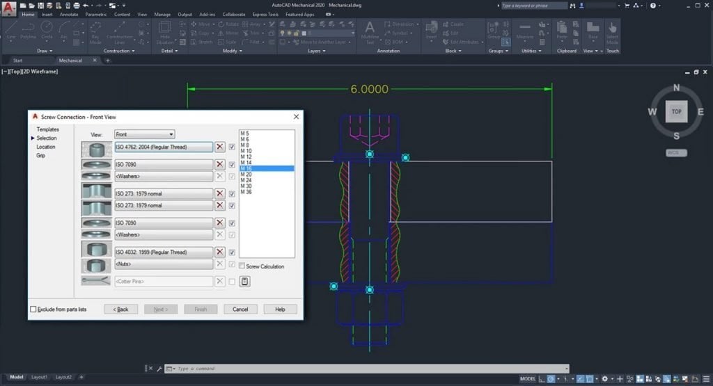
  5. Comprehensive Standard Parts Library:  Autodesk AutoCAD Mechanical includes a vast library of over 100,000 pre-drawn standard features such as undercuts, keyways, and thread ends, and more than 8,000 pre-drawn holes including through holes, blind holes, counterbored holes, countersunk holes, and oblong holes. These features automatically clean up the insertion area in the drawing, eliminating the need for manual editing and significantly speeding up the design process.
  6. Efficient Production Drawing Creation: The toolset makes creating production drawings for parts and assemblies much more efficient. Automated and associative parts lists and bills of materials (BOMs) update automatically as the design changes. This ensures that all documentation is up-to-date and accurate, facilitating smoother transitions to manufacturing and reducing production delays.
  7. Power Commands: AutoCAD Mechanical’s Power Commands utilise object information to accelerate user operations such as editing and copying objects. This feature allows users to bypass traditional pull-down menus, toolbars, and tablet locations, using the objects themselves as command menus. This intuitive interface streamlines the design process and enhances productivity.
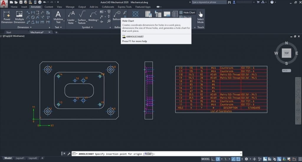
  8. Specialised Drafting Tools: The toolset includes over 30 options for rectangle, arc, and circle creation, nearly automatic centerline creation and updating, speciality lines for breakout views and section lines, and a full suite of construction lines for aligning drafting views. These specialised tools are designed specifically for mechanical drafting, providing more precise and efficient ways to create detailed and accurate drawings.
  9. Foreground/Background Management: AutoCAD Mechanical simplifies the management of foreground and background elements in a drawing. It automatically redraws geometry to show hidden or dashed lines of parts obstructed by other parts in a design. Hidden lines update automatically when changes occur, eliminating the need for manual redrawing due to design changes. This feature ensures that designs are always clear and accurate, reducing the time and effort required to update 2D designs.

These advantages make Autodesk AutoCAD Mechanical an indispensable tool for mechanical engineers and designers, enabling them to produce high-quality, precise, and efficient designs with less effort and in less time. Whether you’re working on simple components or complex assemblies, the Mechanical toolset offers the functionality and flexibility needed to meet the demands of modern mechanical design.

Embrace the Future of Mechanical Drafting with Autodesk AutoCAD Mechanical

Autodesk AutoCAD Mechanical is a powerful toolset that revolutionises mechanical drafting by enhancing productivity, reducing errors, and automating routine tasks. Whether you’re designing complex machinery, optimising existing designs, or calculating forces in a mechanism, AutoCAD Mechanical provides the tools and features you need to work more efficiently and accurately.

By incorporating AutoCAD Mechanical into your workflow, you can significantly cut down on design and rework time, allowing you to focus on innovation and quality. Embrace the marvels of mechanical drafting with AutoCAD Mechanical and take your engineering projects to new heights.

Contact Us

Contact us to find out how we can help your business. Fill out the form below, by live chat, phone or email.

P: 1800 490 514 |  E: [email protected]

Connected Design

Design Consulting Autodesk Gold Partner
about design consulting Moving at the Speed of Business

VIEW MORE

AutoCAD vs. Autodesk Advance Steel: Choosing the Right Tool for Your Design Needs

Autodesk Advance Steel Integration

AutoCAD vs. Autodesk Advance Steel: Choosing the Right Tool for Your Design Needs

Imagine you’ve just spent hours meticulously designing a product in AutoCAD, only to realise there might be a more efficient tool for your specific needs. You’re not alone. With the ever-evolving landscape of computer-aided design (CAD) software, many professionals find themselves at a crossroads, wondering if they’re using the optimal solution for their projects.

Enter the AutoCAD vs. Autodesk Advance Steel debate. These two Autodesk powerhouses each bring unique strengths to the table, but which one is right for you? Whether you’re an architect sketching the next skyline-defining structure or a steel fabricator planning intricate industrial components, choosing the right CAD software can dramatically impact your workflow and output.

In this article, we’ll dive deep into the world of AutoCAD and Autodesk Advance Steel, comparing their features, applications, and market positions. By the end, you’ll have a clear understanding of which tool aligns best with your design needs, potentially saving you countless hours and resources in the long run. So, are you ready to optimise your CAD experience? Let’s get started.

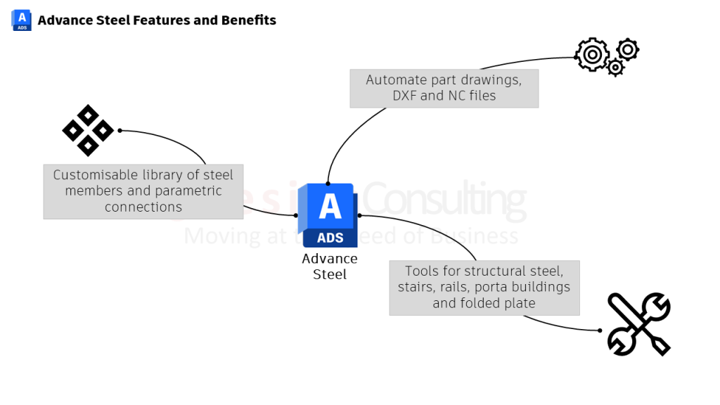
Advance Steel Features and Benefits Moving at the Speed of Business

Understanding the Basics

AutoCAD is renowned for its versatility, catering to a broad user base that includes architects, engineers, drafters, and designers across diverse industries such as construction, manufacturing, and product design. It offers robust 2D and 3D CAD capabilities, making it a go-to solution for professionals who require flexibility in their design work and need to create detailed technical drawings across different disciplines. AutoCAD’s general-purpose nature allows it to be used for a wide range of applications, from architectural blueprints to mechanical parts design, making it an essential tool for many design professionals.

Autodesk Advance Steel is a specialised software designed for structural engineers, steel detailers, and fabricators working on steel construction projects. It excels in creating detailed 3D models of steel structures, generating fabrication drawings, and producing bills of materials with high efficiency. The software’s automated features and steel-specific tools significantly reduce design time, making it invaluable for large-scale steel fabrication projects. By focusing on the specific needs of steel fabrication, Advance Steel offers features that streamline workflows and improve accuracy, ensuring that steel projects are completed efficiently and to exact standards.

Key Differences Between AutoCAD and Autodesk Advance Steel

1. Purpose and Specialisation

AutoCAD is a general-purpose 2D and 3D CAD software used across various industries for drafting and modelling. Its versatility makes it suitable for a wide range of applications, from architectural design to engineering and product development. In contrast, Autodesk Advance Steel is a specialised software designed specifically for steel fabrication, detailing, and structural engineering. This specialisation allows Advance Steel to provide tools and features tailored to the needs of steel professionals, ensuring that projects are completed with precision and efficiency.

2. Modelling Capabilities

AutoCAD offers both 2D and 3D drafting and modelling tools, making it a versatile choice for professionals in various fields. It can handle everything from simple sketches to complex 3D models, providing flexibility for different design needs. Advance Steel, however, is purpose-built for 3D modelling of steel structures and components. It adheres to global steel standards, ensuring designs meet industry requirements. This focus on steel modelling allows Advance Steel to provide more accurate and efficient tools for creating detailed steel structures.

3. Automation and Efficiency

While AutoCAD provides some automation features, much of the drawing and detailing work is done manually, which can be time-consuming for large projects. Advance Steel, on the other hand, offers extensive automation specifically for steel fabrication. It can automatically produce detailed fabrication drawings in minutes, significantly reducing project timelines from weeks to days. The software includes a library of common connections and allows users to save custom connections for future use, enhancing efficiency and consistency across projects.

4. Drawing Production

In AutoCAD, most drawings and details are created manually, which can be labour-intensive and prone to errors. Advance Steel utilises purpose-built templates for creating drawings, tailored for steel fabrication. These templates account for different styles, processes, and views, streamlining the drawing process and ensuring consistency. Users can modify these templates to match their company standards, enhancing the software’s adaptability and efficiency.

5. Ease of Use for Steel Work

Advance Steel simplifies steel modelling with user-friendly features. Basic steel modelling is as straightforward as drawing lines in AutoCAD, with the added benefit of automated setup of layers and organisation of elements. This ease of use maximises efficiency in steel detailing, allowing users to focus on design rather than software intricacies. AutoCAD, while versatile, may require more manual setup and management, making it less efficient for steel-specific tasks compared to Advance Steel.

6. Integration and Workflow

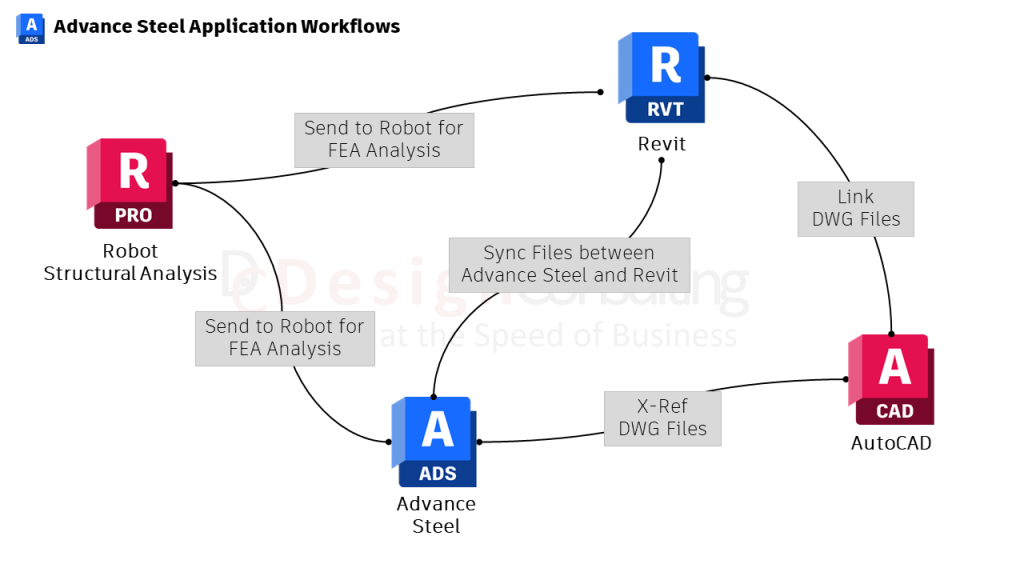
Both AutoCAD and Advance Steel can be used in conjunction, but they follow different workflows. Models created in Autodesk Advance Steel can be exported and imported into AutoCAD or Autodesk Inventor for further work in mixed design environments. This integration allows for seamless collaboration between different software, enhancing workflow efficiency and ensuring that all aspects of a project are covered. AutoCAD’s general-purpose nature makes it adaptable to various workflows, but Advance Steel’s specialised features offer a more streamlined process for steel projects.

Advance Steel Application Workflows Moving at the Speed of Business

7. Learning Curve

AutoCAD, with its broad application scope, may require more time to master all its features. Its versatility means that users must familiarise themselves with a wide range of tools and capabilities. Advance Steel, being more specialised, can be learned more quickly for steel-specific work. Some users report being able to handle significant projects after just a few days of training, thanks to the software’s focused feature set and user-friendly design.

8. Document Management

Advance Steel offers more integrated document management for steel projects. Changes made to parts can be quickly updated in parts lists using the “Force Update” option, ensuring that all project documentation is accurate and up to date. This level of integration simplifies project management and reduces the risk of errors. AutoCAD, while offering robust documentation capabilities, may require more manual updates and management, making it less efficient for complex steel projects.

Practical Applications and User Scenarios

AutoCAD’s versatility makes it an ideal choice for professionals who work on diverse projects across multiple industries. Whether you are an architect designing residential buildings, an engineer drafting mechanical parts, or a product designer creating prototypes, AutoCAD provides the flexibility and comprehensive toolset needed for a wide range of applications. Its general-purpose capabilities make it an invaluable asset for any professional who requires a reliable and adaptable CAD solution.

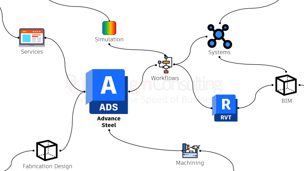
Autodesk Advance Steel Integration

Advance Steel is the go-to solution for professionals focused on steel fabrication and structural engineering. Its specialised tools and efficiency are unmatched for those involved in large-scale steel construction projects. Structural engineers, steel detailers, and fabricators benefit from its ability to create detailed 3D models, generate fabrication drawings quickly, and produce accurate bills of materials. Companies that require interoperability with other Building Information Modeling (BIM) software and need to conform to global steel standards will find Advance Steel particularly beneficial.

AutoCAD or Autodesk Advance Steel, Make the Right Choice For Your Needs

Choosing between AutoCAD and Advance Steel ultimately depends on your specific needs and the nature of your projects. Both AutoCAD and Advance Steel are powerful tools within the Autodesk suite, each designed to cater to distinct professional needs. By understanding their unique capabilities and how they align with your project requirements, you can make an informed decision that enhances your design process and overall productivity.

That said, if you’re involved in large-scale steel construction, our recommendation is Autodesk Advance Steel, as its specialised tools can drastically reduce design time and improve workflow efficiency.

If you want to learn more about Autodesk Advance Steel and Autodesk’s other fabrication tools, click here.

Contact Us

Contact us to find out how we can help your business. Fill out the form below, by live chat, phone or email.

P: 1800 490 514 |  E: [email protected]

Connected Design

Design Consulting Autodesk Gold Partner
about design consulting Moving at the Speed of Business

VIEW MORE

The Ultimate Guide to Design Consulting’s Visualisation Apps and Services

Design Consulting

The Ultimate Guide to Design Consulting’s Visualisation Apps and Services

Design Consulting

In a world where visuals speak louder than words, the ability to present your ideas clearly and attractively can set your business apart. Design Consulting understands this need and has developed a suite of sophisticated visualisation tools to help businesses communicate their visions with precision and flair.

This guide will walk you through our innovative batch rendering configurators and web product configurators, showing how these tools can boost efficiency, ensure accuracy, and elevate customer satisfaction.

The Evolution of Visualisation

Visualisation technology has drastically evolved, transforming from basic 2D drawings to sophisticated 3D models and interactive configurators. We have leveraged this evolution, integrating the latest technologies to provide robust visualisation solutions that meet the diverse needs of modern businesses.

Early Days: 2D Drawings

Initially, design firms relied on 2D drawings to convey design concepts. While effective, these drawings often lacked the depth and realism needed to fully communicate the intricacies of a project.

The Shift to 3D Modelling

The advent of 3D modelling revolutionised the industry. We quickly adopted this technology, enabling us to create detailed, realistic representations of projects. This shift allowed for better client communication and more accurate project planning.

Interactive Configurators: The New Frontier

Today, interactive configurators represent the pinnacle of visualisation technology. These tools allow clients to interact with designs in real-time, making changes and customisations on the fly. Our adoption of batch rendering and web product configurators has positioned them as a leader in this space.

Design Consulting
Design Consulting

Understanding Batch Rendering Configurators

Batch rendering configurators are powerful tools that automate the process of generating high-quality visualisations for multiple configurations of a product or design. Here’s how they work and their benefits:

What Is Batch Rendering?

Batch rendering involves processing multiple render jobs simultaneously, producing a series of images or animations from various angles and configurations. This method saves significant time and ensures consistency across all visual outputs.

Benefits of Batch Rendering Configurators

    • Efficiency: Automating the rendering process reduces the time needed to produce high-quality visualisations.
    • Consistency: Ensures all renderings maintain the same quality and visual standards.
    • Scalability: Easily handles large projects with numerous configurations, making it ideal for complex designs.

Applications in Various Industries

Batch rendering configurators are invaluable in industries such as architecture, automotive, and product design, where multiple design variations need to be visualised quickly and accurately.

Exploring Web Product Configurators

Web product configurators offer an interactive platform for clients to customise products online. These tools enhance user experience and streamline the design approval process.

How Web Product Configurators Work

Web product configurators allow users to modify design elements, such as colours, materials, and features, directly on a web interface. Changes are rendered in real-time, providing immediate visual feedback.

Benefits of Web Product Configurators

    • User Engagement: Clients can interact with and customise products, leading to higher satisfaction and engagement.
    • Real-Time Visualisation: Immediate visual feedback helps clients make informed decisions quickly.
    • Reduced Errors: Interactive configurators minimise the risk of misunderstandings and errors in the final product.

Real-World Applications

Web product configurators are widely used in e-commerce, interior design, and bespoke manufacturing. They allow customers to visualise and personalise products before purchase, enhancing the overall buying experience.

Design Consulting’s Visualisation Services

Design Consulting offers a range of visualisation services tailored to meet the unique needs of each client. Here’s an overview of their key offerings:

Custom 3D Modelling

Their custom 3D modelling services transform concepts into detailed digital models. These models serve as the foundation for all visualisation efforts, ensuring accuracy and realism.

Photorealistic Rendering

Photorealistic rendering services produce lifelike images that capture every detail of a design. This level of detail is crucial for client presentations and marketing materials.

Interactive Presentations

Interactive presentations allow clients to explore designs in a dynamic, engaging manner. These presentations often incorporate elements like virtual reality (VR) and augmented reality (AR) to provide immersive experiences.

Virtual Tours

Virtual tours enable clients to explore a space as if they were physically present. This service is particularly beneficial for real estate and architecture clients looking to showcase properties.

How to Choose the Right Visualisation Service for Your Needs

Selecting the right visualisation service can be daunting, given the myriad of options available. Here are some tips to help you make an informed decision:

Assess Your Project Requirements

Before choosing a visualisation service, clearly define your project’s needs. Are you looking for detailed 3D models, photorealistic renders, or interactive configurators? Understanding your requirements will help you select the most appropriate service.

Consider Your Budget

Visualisation services can vary significantly in cost. While advanced features like real-time configurators and VR experiences are impressive, they can also be expensive. Evaluate your budget and choose services that provide the best value without compromising on quality.

Look for Expertise and Experience

Choose a provider with a proven track record and expertise in your industry. Design Consulting, for instance, has extensive experience across various sectors, ensuring they understand the unique challenges and requirements of your projects.

Request a Portfolio

Reviewing a provider’s portfolio can give you insights into their capabilities and the quality of their work. Look for examples that align with your project’s scope and complexity.

Evaluate Client Feedback

Client testimonials and reviews can provide valuable information about a provider’s reliability and customer service. Positive feedback from previous clients is a good indicator of a trustworthy and competent service provider.

Transform Your Business with Advanced Visualisation Solutions

With visual communication becoming more critical than ever, we are dedicated to helping businesses with our state-of-the-art visualisation apps and services. From batch rendering configurators to web product configurators, they offer tools that streamline processes, enhance client engagement, and ensure high-quality outputs. By choosing our services, you can stay ahead of the competition, impress your clients, and bring your design visions to life with unparalleled precision and creativity.

Whether you are in architecture, product design, or e-commerce, leveraging these advanced visualisation tools will undoubtedly elevate your projects and transform your business. Don’t miss the opportunity to collaborate with a leader in the visualisation industry—reach out to our team and experience the future of visualisation today.

Frequently Asked Questions (FAQs)

What Is the Difference Between Batch Rendering and Real-Time Rendering?

Batch rendering processes multiple render jobs simultaneously and is ideal for creating high-quality visualisations of various configurations. Real-time rendering, on the other hand, generates visualisations instantly, allowing for interactive and dynamic adjustments.

How Can Web Product Configurators Benefit My E-Commerce Business?

Web product configurators enhance user engagement by allowing customers to personalise products online. This interactive experience can lead to higher customer satisfaction, increased sales, and reduced returns due to mismatched expectations.

Can Your Visualisation Services Be Integrated with Existing Design Software?

Yes, our services are compatible with most industry-standard design software, ensuring seamless integration and workflow efficiency.

What Industries Can Benefit from Your Visualisation Services?

Our visualisation services are versatile and can benefit a wide range of industries, including architecture, real estate, automotive, product design, and e-commerce.

How Do I Get Started with Design Consulting’s Visualisation Services?

To get started, simply contact us to discuss your project requirements. Our team will work with you to develop a customised visualisation solution that meets your needs and exceeds your expectations.

Contact Us

Contact us to find out how we can help your business. Fill out the form below, by live chat, phone or email.

P: 1800 490 514 |  E: [email protected]

Connected Design

Design Consulting Autodesk Gold Partner
about design consulting Moving at the Speed of Business

autocad architecture vs autocad lt, AutoCAD LT vs AutoCAD architecture

VIEW MORE

What’s New in Maya 2022

Maya 2022 Moving at the Speed of Business

What's New in Autodesk Maya 2022

Maya 2022 brings seamless USD integration, improvements to animation, rigging and modelling toolsets and the latest version of Arnold.

USD Plug-in for Maya

Universal Scene Description (USD) support in Maya is now available:

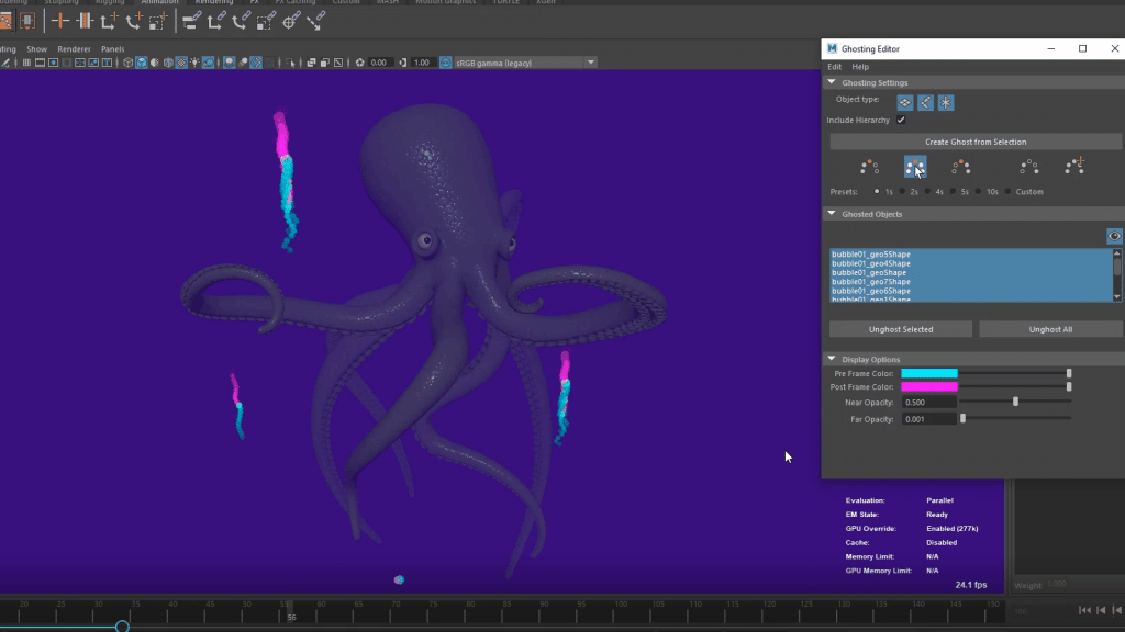
Animation Ghosting

In previous versions of Maya when you wanted to change the way ghosts appeared with multiple meshes selected, each of their attributes had to be edited individually in the Attributes editor.

The new Ghosting editor gives you an interface to apply Ghost attributes individually or as a group.

Component Tags for Deformers

Component Tags let you create node-independent named groups to deform geometry, letting you modify tag membership on the fly.

Using Component Tags replaces the groupID node previously needed to transform vertices, as well as cleans up the Node Editor by eliminating Tweak nodes. Component Tag nodes are automatically created with a subset of components selected whenever you create a deformer.

Create and edit Component Tag membership with the Component Tags table

Python 3

In Windows and Linux, Maya starts in Python 3 by default and available on all platforms

Bifrost 2.2.1.0 plug-in

The new Bifrost plugin has simulation workflow enhancements, e.g. resume simulation from cached frame, spawn new particles and low-resolution Aero refinement.

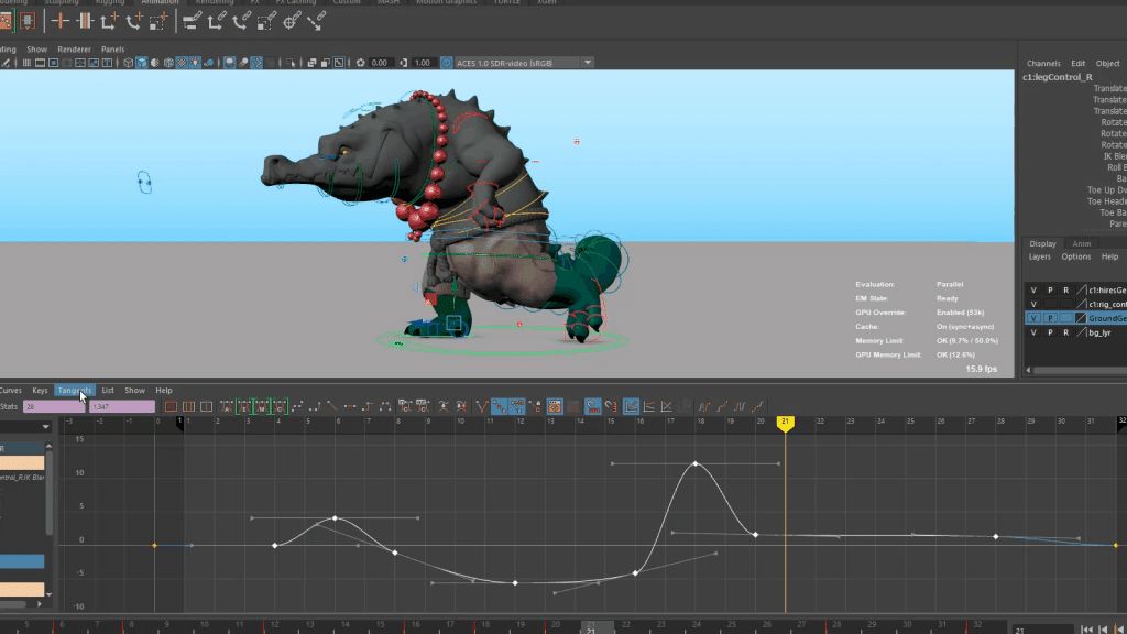
Graph Editor Improvements

Peak Removal Filter to clean up noisy animation data

Added to the Graph Editor Curves menu, is a new animation filter, the Peak Removal Filter.

Similar to the MotionBuilder filter of the same name, the Peak Removal Filter lets you clean up unwanted spikes and peaks in your animation curves.

Smooth filter (Gaussian) for curve "noise" reduction

Another new MotionBuilder filter, the Smooth filter (Gaussian) has been added to the Graph Editor Curves menu, to let you remove jittering and noise in curve channels. See Smooth filter (Gaussian) options for details.

New Display Option

A new Show Animated Shapes option in the Graph Editor List menu lets you set whether the Graph Editor displays all curves downstream from a node, or just the animation curve of the selected node. This is useful if you have custom rigs with specialized connections or when animators only want to view the transforms for a selected object.

Preserve Tangent Type Now for Added Keys Moving at the Speed of Business
Preserve Tangent Type for Added keys: on (default)

Preserve Tangent Type: Now for Added Keys

The Preserve Tangent Type option, formerly only for Inserted Keys, is now available for Added Keys.

Previously, when you added a key to a curve, by default, the new key respected the tangents on either side of the key. This ensured that added keys did not change the neighbouring tangents type while still changing the shape of the curve. This behaviour continues to be the default setting.

Preserve Tangent Type Now for Added Keys OFF Moving at the Speed of Business
Preserve Tangent Type for Added keys: off

Customise Key Selection

You can now shrink the active selection area of keys in the Graph Editor graph view by using the Min key selection size in the Animation (Settings) preferences. 

Sweep Mesh

Meshes can be created from simple curves using the Sweep Mesh feature using various profiles letting you create a wide array organic and hard surface forms like:

  • Tubes
  • Pipes
  • Ribbons
  • Cables
  • Ropes
  • Roads
  • Horns
  • Hair Cards
  • Architectural features (e.g. crownmoulding)

Security Preferences

Flag specific commands or plugin locations to be blocked when Maya loads them in the Preferences window.

Rokoko Motion Library Plug-in

Drag and drop professional mocap assets into your scenes, leveraging on assets built for big productions like Star Wars: The Last Jedi, Doctor Strange, Assassin’s Creed, and Horizon Zero Dawn in your own projects.

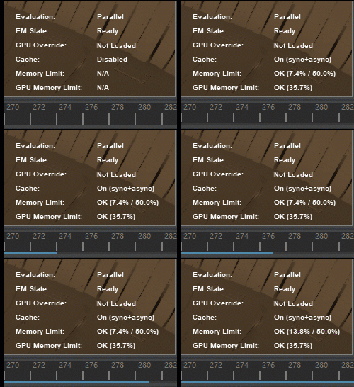
Cached Playback Improvements

In previous versions of Maya, you could turn on Caching support for dynamics nodes such as Boss, or Nucleus. Now, Cached Playback for dynamics is on by default and dynamics simulation content caching is shown in a separate pass that appears as a pink status line in the Time Slider just above the Animation Cache Status line.

New Solidify Deformer

The new Solidify deformer lets you create areas of geometry that appear more solid on deformed geometry, which lets you define rigid parts of a character’s clothes, such as buttons or a belt buckle.

It works by analysing deformed sections of geometry and dividing it into separate polygon islands. Each polygon island is then replaced by the original geometry moved and blended into place based on the approximation of the matrix derived from the deformed vertices.

OpenColorIO v2

With an emphasis on visual effects and computer animation, the OpenColor IO v2 colour management system has been integrated into Maya 2022

Start up Experience Improvements

A number of improvements have been made to Maya’s startup experience, including:

  • Faster start up and quit times
  • No longer steals focus during start up
  • Remembering the state of the Output Window
  • Ability to copy specific preferences from a previous install
  • A new, more informative splash screen

New Morph Deformer

The new Morph deformer is like a GPU-Accelerated version of the BlendShape deformer.

With a GPU-Accelerated version of the BlendShape deformer, it provides simple AB morphs, partial to whole mesh morphs (or whole mesh to partial), as well as the ability to incorporate legacy CPU deformers in deformation chains without blocking the rest of the chain from GPU evaluation.

It features:

  • Absolute, Relative, and Surface Space morph modes
  • Object and World morph spaces
  • An option that automatically creates a topology Mapping feature for alternate vert table lookup
  • Neighbour options for stabilizing Relative space morph mode coordinate system

HUD: Updated Evaluation Manager Status Messaging

Changes have been made to the Maya Heads Up Display (HUD) Evaluation Manager status messages to better reflect the condition of the Evaluation Manager (EM).

The previous “Rebuild Required”, then “Ready” (but still requiring partitioning) status messaging was unclear if the EM was performing Parallel evaluation.

The new status messaging is now Rebuild Required, then Built, followed by Ready, states that depict each stage of the Evaluation Graph as it is unbuilt, built, and partitioned.

To display this information on the Viewport, go to Display > Heads Up Display and choose the Evaluation option.

Time Slider Bookmark Improvements

New functionalities have been added to Time Slider Bookmarks:

  • Interactive Move and Scale
  • Step through bookmarks
  • Move frames with bookmarks
  • Bookmark Manager


Deformer Updates

Falloff applied to a Wave deformer Moving at the Speed of Business
Falloff applied to a Wave deformer
Deformer Falloff effects Moving at the Speed of Business
Deformer Falloff effects
Falloff support for Skin Cluster Moving at the Speed of Business
Falloff support for Skin Cluster

HumanIK: Neck Motion Reduction setting

A new Neck Motion Reduction slider has been added that lets you minimize the movement from a character’s body to its neck.

Updated System Requirements

Minimum Linux system requirements for Maya have changed, and new Visual Studio and gcc versions are now supported.

On Windows, Visual Studio has been updated to 2019.7. There are no changes to Windows system requirements.

On Linux, gcc has been updated to 9.3.1. Linux users will require CentOS 7.6 or higher to use this preview release. They will also need to ensure that these additional libraries are installed to run Maya:
  • libxcb-icccm.so.4 from package xcb-util-wm
  • libxcb-image.so.0 from package xcb-util-image
  • libxcb-keysyms.so.1 from package xcb-util-keysyms
  • libxcb-render-util.so.0 from package xcb-util-renderutil

Create VR for Maya

Create VR for Maya is an immersive conceptual design tool that empowers artists and designers to start their creative process directly in 3D. Using simple curve and surface tools designers can explore form and shape while being fully immersed in virtual reality alongside their design. Sketches and models can then be easily exported to Maya or other content creation applications for final realization.

Arnold for Maya 4.2.1 plug-in

Maya 2022 includes MtoA 4.2.1 which introduces Arnold 6.2.0.1, and is a feature release that brings light mixing, bloom and interactive denoising through imagers, better USD support to improve your experience working with USD in Maya, an improved layout to the Arnold Render View, and OSL syntax highlighting to the OSL shader.

Auto Tangent Types

New options for Auto Tangents in the Graph Editor offer an improved algorithm, giving animators better control and more predictable results.

Contact Us

If you would to discuss Autodesk software, please contact us by calling on 1800 490 514, by filling out the form or clicking the live chat in the bottom right-hand corner.

VIEW MORE

What’s New in Autodesk Revit 2022

Whats new in Revit 2022 Moving at the Speed of Business

What's New in Autodesk Revit 2022

Autodesk Revit 2022’s main focus has been on four main areas:

  • Design Productivity across Architecture, Civil, MEP and Structure
  • Interoperability workflow enhancements between Revit and both Autodesk and third-party tools, coupled with support for open standards and additional file formats for data exchange.
  • Documentation Efficiency improvements to schedules, tags, annotations, graphics, and similar features.
  • Developer Tools with additional capabilities offered via Dynamo and the Revit API.

Design Productivity

Tapered Walls

The 2022 release now has tapered walls.

  • Specify sloping angles for interior and exterior surfaces
  • Override type slope properties at the instance level
  • Edit Profile for Slanted Walls

Change any wall to a tapered wall by changing the cross-section parameter to tapered.

Update the sloping angles using instance overrides or the wall’s temporary dimensions.

Align wall-hosted components to the sloped interior or exterior faces of the wall with clean joins at corner conditions. 

Modify the sketch boundaries of a slanted wall along its work plane. 

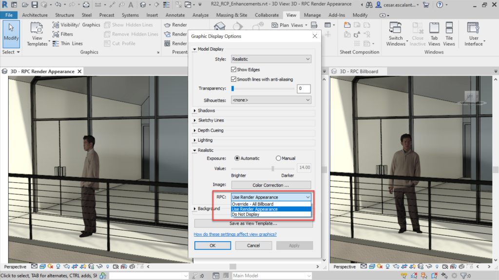
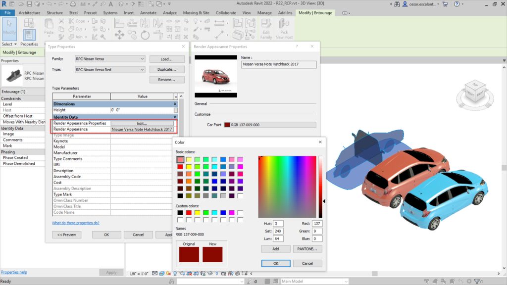
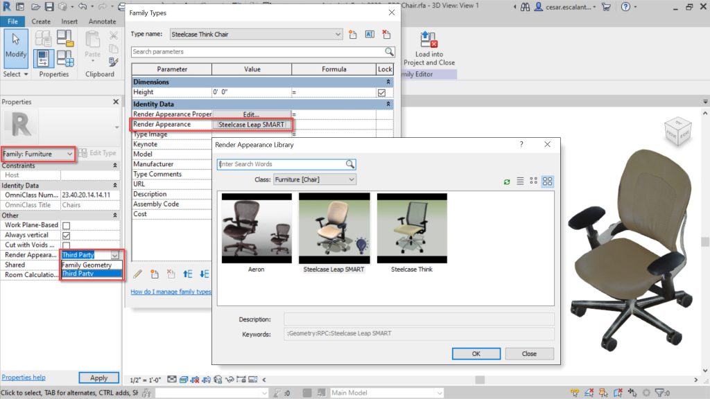
Enhanced RPCs in Realistic Views

2022 now supports the RPC 2.0 file format:

  • Display complex geometries, physical-based materials and lighting
  • ‘Billboard’ mode orients RPCs towards the camera
  • Use RPC for Furniture Category
  • Expanded RCP Asset Library

The support of the RPC 2.0 format displays high-resolution, complex images with physical-based materials and lighting with greater parameter intelligence and control.

Generative Design

The following generative design enhancements have been added:

  • New Sample Study Types
  • Save Default Settings
  • Drop-down Inputs
  • Constant and Variable Inputs
  • Manage Study Type Folders
  • Improved Generative Design Tools panel in Dynamo for publishing study types
  • Receive alerts for graph issues
  • Resolve missing packages
  • Detect missing ‘Remember’ nodes

Route Analysis Tools

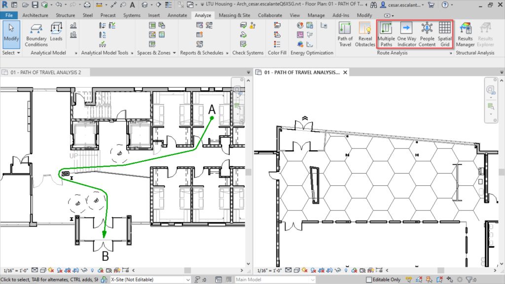
The People Flow Toolkit technology preview has been added into Revit as standard, providing four new tools under Route Analysis to visualise, automate and analyse the impacts of physical distancing and routes within a design.

  • Generate multiple paths of travel options between point with the ability to summarise them in a schedule;
  • Indicate the direction of travel with One-Way Indicator family; this indicator of the annotation category can be nested within door families if needed
  • Place people content to represent occupants with built-in buffers. These buffers are recognised as clearances during route analysis; and
  • Overlay a spatial grid in rooms to visually aid in distributing elements to meet prescribed physical separation requirements.

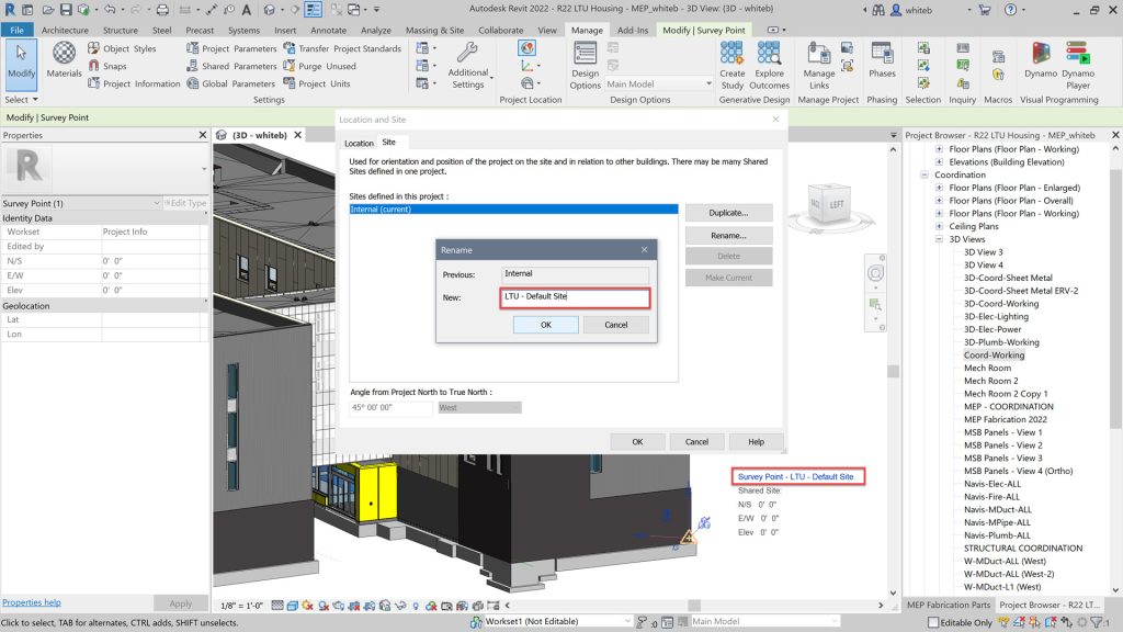
Rename Default Shared Site

  • Clearly named survey point to help avoid confusion
  • Supports all 151 ENU templates for all countries.

Infrastructure Enhancements

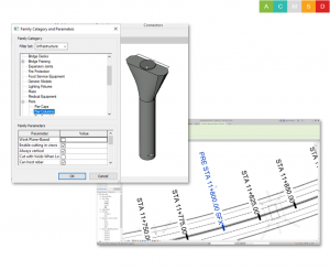
Revit families created using the generic model family template can be assigned to the Bridge and Road categories and subcategories (e.g. Abutments, Piers, and many more).

Rebar can be hosted and be defined as cuttable in views, scheduled, tagged, etc.

There has also been minor enhancements to alignment stationing:

  • Prefixes and suffixes may be added to alignment station text.
  • Flip controls have been added to the alignment station label.
  • The true start and end stations of an alignment are now exposed in the Revit API to help automate bridge design.

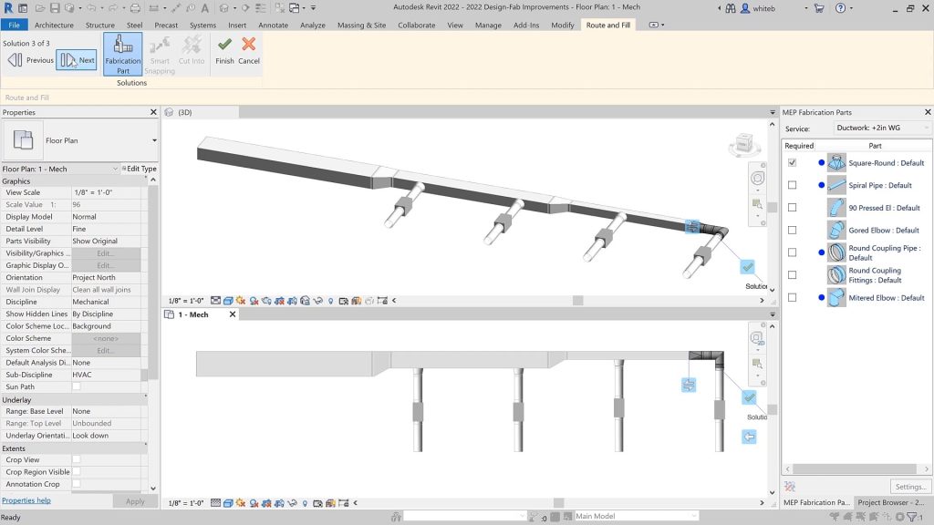
Fabrication Improvements

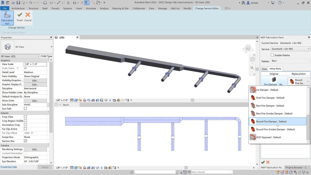
  • There is more flexibility to the Design to Fabrication tool with mapping enabled during the conversion process to fabrication parts.
  • Elements can be connected by dragging connectors in-canvas and design parts and fittings will be placed.
  • Configuration reload process has been optimized to reduce the number of elements checked out while work-sharing, which results in a reduction of the time to process.

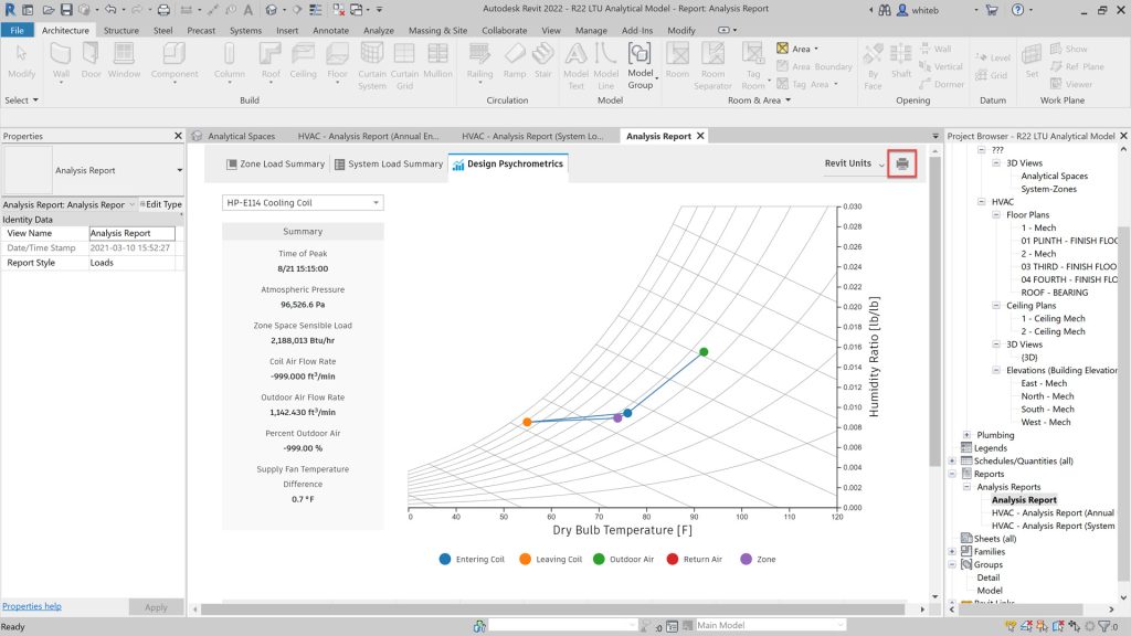
Systems Analysis

A new feature has been included in the Revit Systems Analysis to get more detailed loads and psychrometric reports.

A user can view a floor plan, 3D view or explore results in the report on a single screen.

After running a simulation on a Systems Analysis model view the summary information for QA/QC checks on multiple unit systems. Reports show a breakdown of load components, totals for sizing equipment, a psychrometric chart, and detailed psychrometric state point properties in a printable formats.

The workflows for exporting to gbXML have been consolidated into a new dialog.

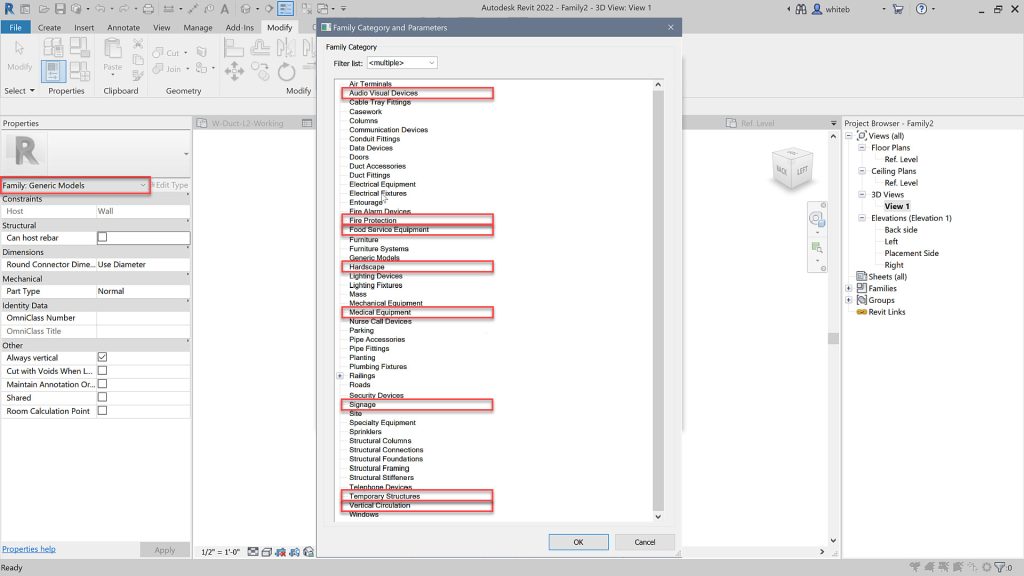
Family Category Improvements

There are new Family Categories for Equipment and Building Elements:

  • Audio Visual Devices
  • Fire Protection
  • Food Service Equipment
  • Hardscape
  • Medical Equipment
  • Signage
  • Temporary Structures
  • Vertical Circulation

Expanded Category List for MCS and MTs has also been included.

When creating multi-category schedules you will find more categories and sub-categories are available in the table.

This improvement enhances the ability to schedule system categories.

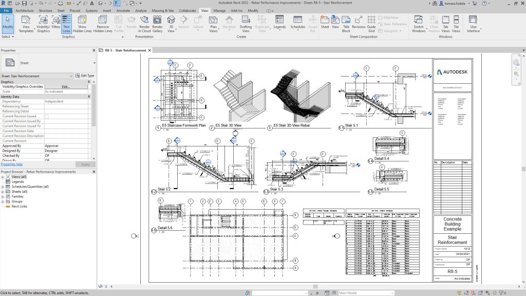
Move Rebar in a Set

Rebar modelling and detailing has been improved in 2022 with the ability for structural enginers and detailers to move/remove individual bars in rebar sets or area and path reinforcement systems to avoid clashes with other rebars, openings or other elements, while maintaining the logic of the rebar set or system.

Model Rebar Using the Real Bar Diameter​

  • New “Model Bar Diameter” parameter
  • Avoid clashes in concrete elements containing many large diameter bars

Rebar Placement by Two Points

  • New placement method
  • Reduces number of steps needed to create bars

Select Shape Code for Custom Bent Free Form Rebar

  • Use the Shape parameter dropdown to assign a new shape
  • Preserve engineering rebar definition

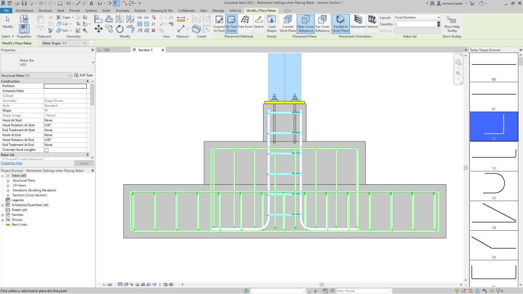
Remember Settings when Placing Rebar

  • Rebar options keep their values when restarting rebar placement
  • No need to reapply rebar settings for each set

Rebar Performance Improvements

  • Improved zooming and panning in 2D views at Fine detail
  • Quick regeneration of views containing rebars

Improved Parameter Identification UI

Revit 2022 allows you to quickly filter and find available parameters when creating schedules or when working with project parameters.

When you create a schedule or when working in the Project Parameters dialog, the Fields tab in the Schedule Properties dialog includes a filter section

Filter the available parameters based on the following criteria: Parameter Name, Parameter Type, Discipline, Value, Type or Instance

Load Autodesk Family

Previously a technology preview, this new addition allows you to load content provided by Autodesk through a cloud repository.

Interoperability

Native 2D PDF Export

A native, configurable 2D PDF export feature is included in Autodesk Revit 2022.

Offering similar options to the Print dialog, such as a user-defined selection of views and sheets or the ability to export the visible portion of a view.

In the the Export Setup section of the dialog, users can setup PDF naming rules and can use this feature to generate PDF file names automatically based on your project or shared name parameters.

By automatically analysing the the selected views and sheets, the exporter can detect output size and orientation.

Link Rhinoceros® (3DM) Files

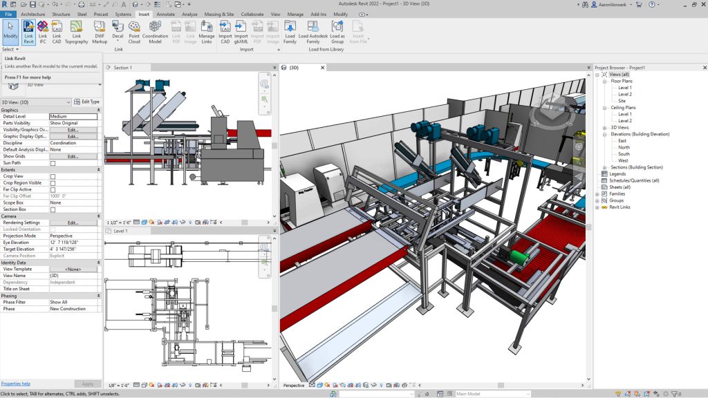
Link a Rhino (3DM) file into Revit and if the source file changes, users can reload the file and it will update inside of Revit.

In addition, you can link your Rhino files in Autodesk Docs.

3D Sketch and Send to Revit with FormIt Pro

  • Translate Revit geometry into FormIt using the new 3D Sketch tool
  • Send FormIt geometry into Revit, preserving materials and layers
  • Control FormIt layers via Visibility/Graphics

Import FormIt as a CAD Format

  • Import AXM files with preserved materials, layers and group definitions
  • Control the display of layers via Visibility/Graphics
  • Faster performance
revit 2022 ifc4 certifications

IFC4 Certifications

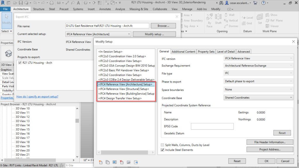
Revit 2022 has achieved IFC4 Reference View certification for architecure and structure exports.

The IFC property set definitions and the associated Revit shared parameter definitions have been updated with the latest IFC4 PSDs of version 4.0.2.2 (partial update from the scope of IFC4 RV1.2 MVD).

Performance of linking in some IFC files containing elements with many parameters has been improved and Autodesk has added the ability for IfcExporter to pick up information from SiteLocation regarding the GeoCoordinateReference in EPSG code format as required by IFC. 

Inventor to Revit Models

Revit can now maintain a link between Revit and Inventor by using the Revit exporter from Inventor.

2D Shared Views

  • Share 2D views and sheets of your Revit project with other stakeholders
  • View, comment and mark up the result in a web browser
  • View and response to comments and markups directly in Revit

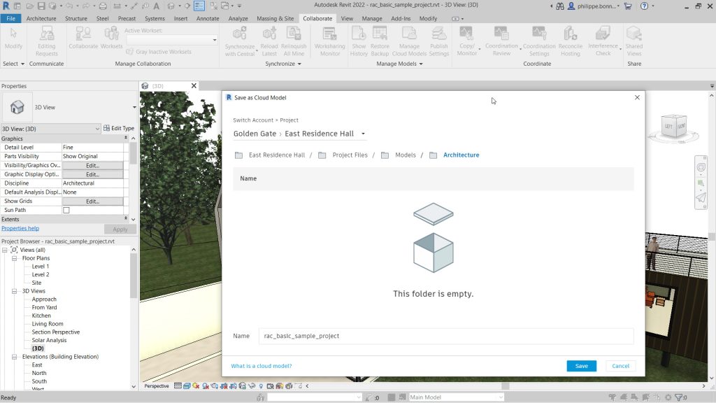
Cloud Model Improvements

  • Open Cloud Model from File Menu
  • Unified Cloud Model Initiate UI
  • Access to Autodesk Docs

Documentation Efficiency

Enable Scheduling of Worksets

Worksets can now be scheduled in 2022 and users can add a Workset parameter in workshared models when creating a schedule.

The workset parameter can also be accessed when creating takeoffs and lists (view, sheet) and title blocks allowing users to filter and format schedules based on worksets.

Schedule Enhancements

  • Shared Parameters in Key Schedules
  • Filter Schedule by Family and Type
  • Split Schedules Across Sheets

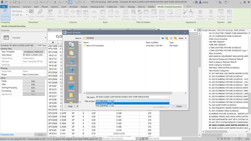
Export Schedules to CSV by Default

Schedules can now be exported as a csv file and when adding a schedule to a sheet, it can be exported as a CAD or CSV.

Multiple Values Indication

  • Display desired text in the Properties Palette when a set of elements is selected with varying parameter values
  • Apply multiple values indication to all types of schedule
  • Customise the indication value

Tag Improvements

The following improvements have been made to:

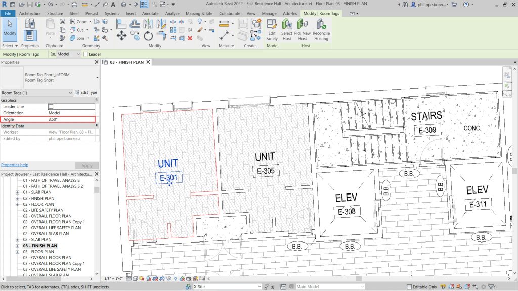
  • Rotated Tags
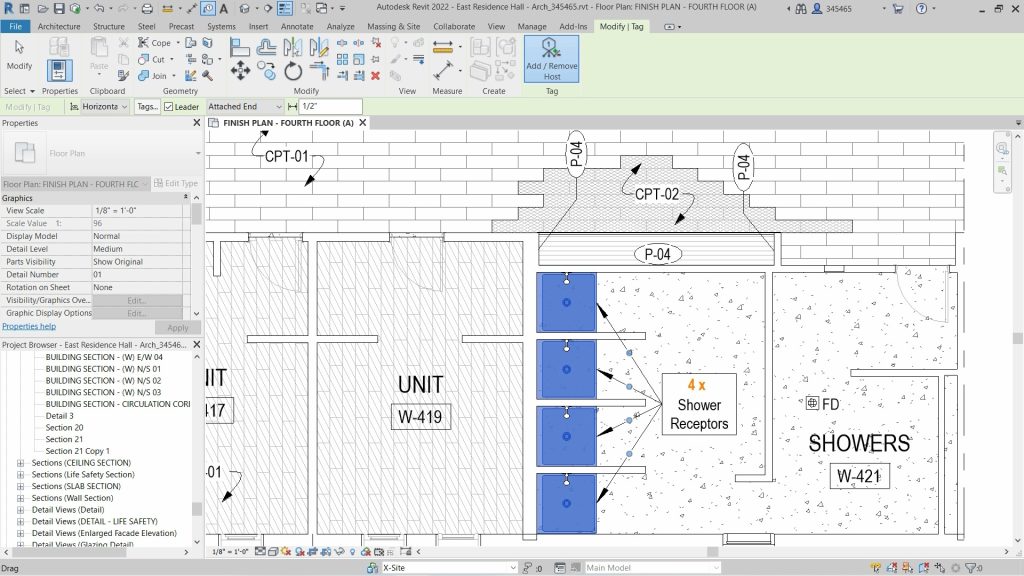
  • Multi-leader tags
  • Tag curtain wall mullions

When you rotate a tag in Revit, a new Angle parameter for tags, found in the Properties Palette is available.

If you rotate the tag with the Rotate command, the angle value is automatically calculated, but you can enter a specific value afterwards if you like.

If a view in your project contains similar elements, you may prefer that they share a tag.

In Revit 2022, users have the ability to apply a single tag to multiple elements and optionally, indicate the total quantity.

Once a tag has been placed in the model, users can add or remove leaders to similar host elements by selecting the tag and using the Add / Remove Host option.

The quantity of host elements is automatically tracked and displayed both in the tag itself and in the Properties Palette.

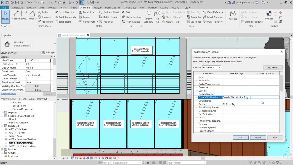
Revit 2022 enables tags to be applied to curtain wall mullions.

A new category has been added for Curtain Wall Mullions in the Loaded Tags and Symbols dialog.

Users can to load the tag for curtain wall mullions provided with Revit 2022 or create their own tag specifically for this category.

Users can use the Tag by Category command or the Tag All command to tag curtain wall mullions.

Multi-category Tag for All Taggable Categories

  • Apply a multi-category annotation to all taggable elements
  • Use shared parameters in multi-category tags
  • Additional categories include stair subcategories, structural connections, structural internal loads, and more

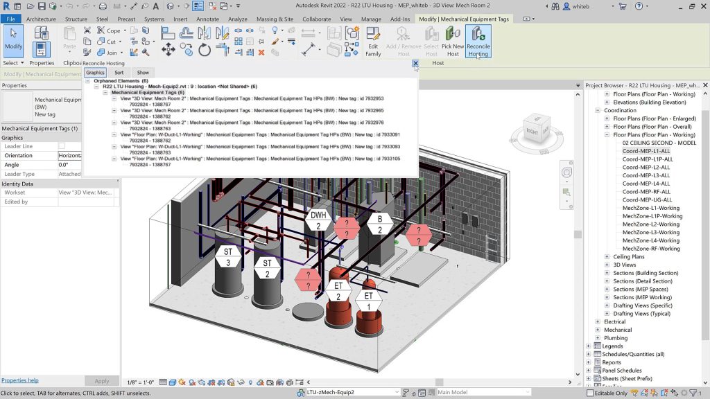
Link Tag Re-hosting

  • Tags in host model attached to elements in a linked model will now remember the linked element ID
  • Unloaded or out-of-date links will reattach orphaned tags automatically when reloaded

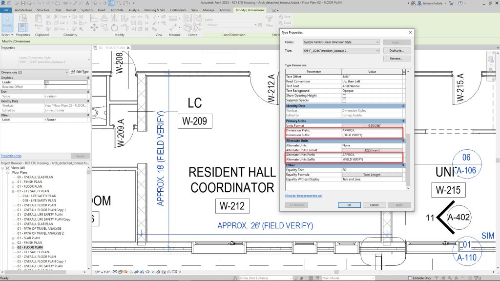
Dimension Prefix/Suffix

  • Add prefix and suffix as type parameters
  • Primary and alternative unit parameters have been reorganised

Revision Numbering Flexibility Enhancements

  • Create custom revision numbering sequences
  • Meet ISO 19650 and/or local standard requirements
  • Add a prefix or suffix to denote a project stage
  • Share using the Transfer Project Standards tools

Spot Slopes and Elevations on Ramps

  • Add spot slope spot elevation annotations on a ramp run in plans, elevations, sections, and 3D views
  • Customize the annotation type parameters to meet documentation standards

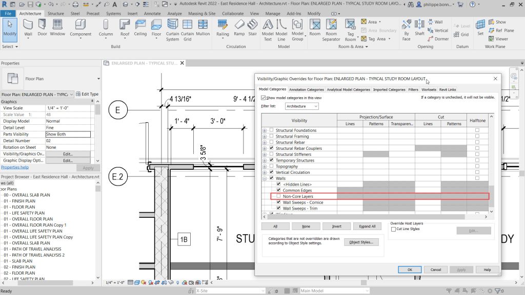
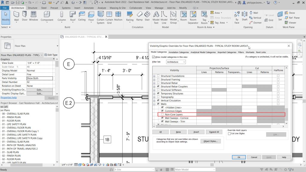
Show Wall Core Only in Plan Views

  • Display a simplified representation of walls in your 2D plan views
  • New “Non-Core Layers” option available under Walls in the Visibility/Graphics dialog box
  • Wall layers located between core boundaries remain visible

Grids in 3D Views

  • Display grid lines in your 3D views
  • Show Grids parameter in the Properties palette
  • Only grids that intersect selected levels appear in the view
  • Grid planes are available on hover or selection

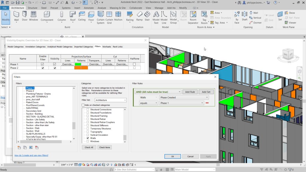
Phase Parameters in View Filters

  • Support phases in view filters
  • Easily locate elements and understand their phases in your model
  • Two new filter rules:
  • Phase Created
  • Phase Demolished

Improved Default Color Fill Scheme

  • New default colour scheme
  • Lighter pastel colours
  • No need for manual colour adjustments

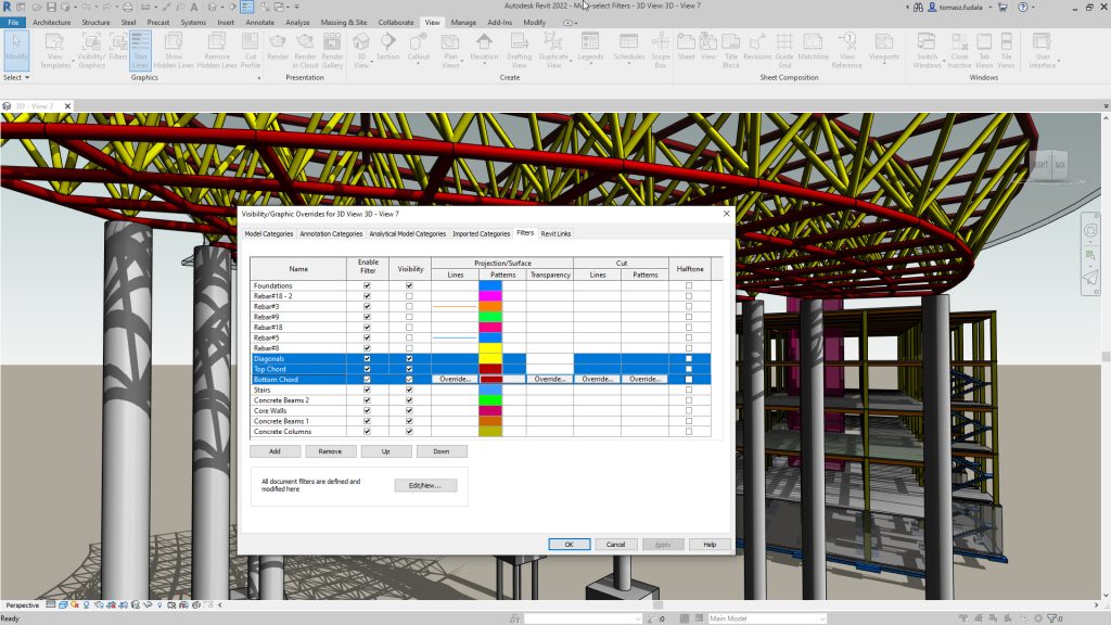
Multi-select Visibility/Graphics Overrides Filters

  • Improved consistency with other Visibility/Graphic Overrides tabs
  • Select, modify, and remove more than one filter in the list at one time
  • Multiple subsequent filters can be moved up or down together, to adjust overall priority

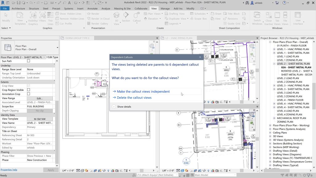
Preserve Callouts When Deleting Parent Views

  • Switch between parent and intersecting Views
  • Callouts in intersecting views are visible
  • Delete parent view and preserve callouts
  • Hide callouts at scales coarser than the size in view

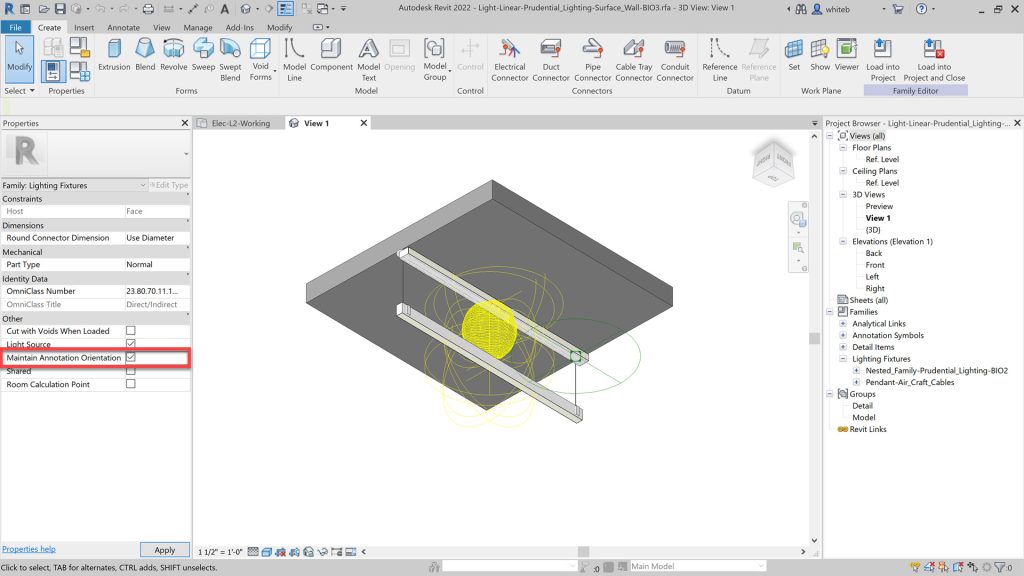
Maintain Annotation Orientation

  • Added to Additional Categories
  • Electrical Equipment
  • Generic Model
  • Lighting Fixtures
  • Mechanical Equipment
  • Plumbing Fixtures
  • Speciality Equipment

Developer Tools

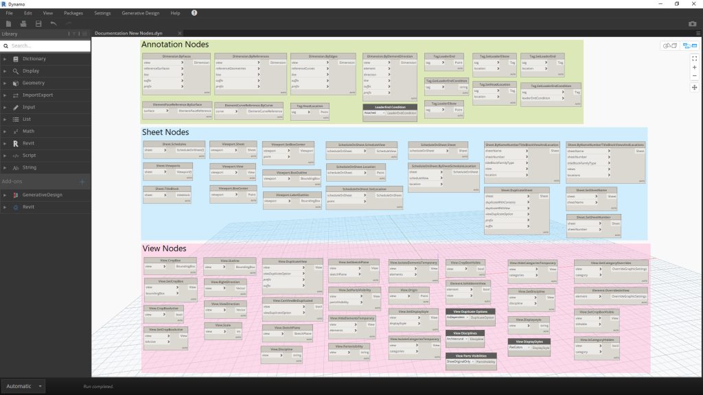
New Dynamo Nodes for Revit Documentation

  • 67 commonly-requested nodes have been added
  • Wide range of categories
  • Annotation nodes
  • Sheet nodes
  • View nodes
  • Dynamo for Revit 2.10 included with Revit 2022

New APIs for Developers

  • Sketch API
  • Viewport Label on Sheet API
  • Color Fill API
  • Cloud Model Initiate and Link API
  • API for Mapping Cloud Model with Autodesk Docs URNs

Contact Us

If you would learn more about Autodesk software, please contact us by calling on 1800 490 514, by filling out the form or clicking the live chat in the bottom right-hand corner.

VIEW MORE

What’s New in 3ds Max 2022

3ds Max 2022 logo Moving at the Speed of Business

What's New in 3ds Max 2022

The focus on the new 3ds Max 2022 has been in the following areas: workflows, texturing, rendering and security.

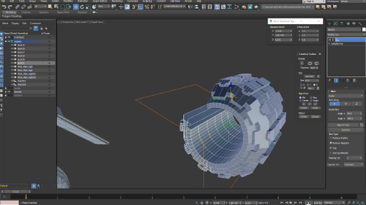
Smart Extrude

The edit Poly modifier now includes Smart Extrude which allows you to extrude with fewer constraints. The adition of the Cut Through command offers further functionality to when Smart Extrude was released in 2021.1

3ds Max 2022 Smart Moving at the Speed of Business
3ds Max 2022 1 Moving at the Speed of Business
3ds Max 2022 Slice Modifier Moving at the Speed of Business

Slice Modifier

The performance of the Slice Modifier has been improved in 2022 with new modelling features based on customer feedback:

  • Capping – cap open holes
  • Multi-Axis Cutting – X, Y and/or Z aligned planar slice
  • Radial Slice – User defined min/max angles
  • Alignment options – align the cutting gizmo to faces or other references.

AutoSmooth

2022 generates new smoothing data faster and is applicable to Mesh, Poly, Spline or in other modifiers such as Chamfer, Smooth, Edit Mesh, Edit Poly, ProOptimize and other modifiers.

Symmerty Modifier

New features and enhancements produce faster results with more user interactivity:

  • Multi-axis Symmetry – Planar symmetry on X, Y and/or Z
  • Radial Symmetry – Quickly duplicate and repeat geometry around the gizmo
  • Alignment – Reference a face or another object in the scene.
3ds Max 2022 Symmetry Modifier Moving at the Speed of Business

Relax Modifier

The volume preserve option reduces small detail and noise from models while maintaining the shape and overall definition and especially useful in scan or sculpt data.

Arnold

  • Auto-tx – automates texture files to .tx at render 
  • New Images tab in the Arnold RenderView to apply, remove, re-order or edit to post-process without additional render time.
  • Light Mixer – Edit the contribution of each light group AOV’s during and after rendering
  • Bloom has been addedd to the Lens Effect
  • Noice and OptiX Denoiser are now possible during post-processing.


3ds Max 2022 Light Moving at the Speed of Business
3ds Max 2022 Presentation Mode Moving at the Speed of Business

Viewports

Full-screen, borderless window from any floating viewport. When using presentation mode, all gizmos are hidden.

Bake to Texture

Simplified inteface offers easier navigation and selection of baked map types.

It also includes utility maps such as rounded corners and MAterial ID maps, making in a few clicks what was complex.

3ds Max 2022 Bake to Moving at the Speed of Business
3ds Max 2022 Malware Removal Moving at the Speed of Business

Security

The safe scene script protects against malware in 3ds scenes.

The Malware Removal tool detects and removes scripts that are malicious.

For more information, check out the public roadmap of 3ds Max which can be found here

Contact Us

If you would learn more about Autodesk software, please contact us by calling on 1800 490 514, by filling out the form or clicking the live chat in the bottom right-hand corner.

VIEW MORE

Autodesk Releases Inventor 2021.2

inventor 2021 badge 1024px Moving at the Speed of Business

Autodesk has released the latest 2021.2 version for Inventor on 30/10/2020 and looking through the list, I find that the list is on improvements and resolving issues rather than new features and functionality.

Here’s the list below. For more information visit the Autodesk Inventor Help page

 
Design Consulting Autodesk Inventor Professional Dynamic Simulation 2 Moving at the Speed of Business

Add-Ins – Cable and Harness

Resolved a Cable & Harness Loom style color cannot be updated issue. INVGEN-41120

Resolved issue where visibility of the components setting is ignored when editing a Cable & Harness sub assembly. INVGEN-43727

Add-Ins – Content Center

Resolved issue where the Place from Content Center icon (Ribbon) switched to Place icon during placing a component from Content Center. INVGEN-32831

Resolved issue where columns with formulas that reference other columns weren’t working correctly. INVGEN-36130

Resolved issue where Content Center commands were enabled for non-master positional representations when switching between documents. INVGEN-37050

Improved performance when placing large Content Center families. INVGEN-39031

Resolved issue for the Chinese version where Boolean values were translated in the opposite direction. INVGEN-43480

Add-Ins – Design Accelerator

Improved the constraint behavior of bolted connections (BC) by applying temporary ground constraints to keep the BC in position when constraining to them. Temporary constraints are removed afterward. INVGEN-39989

Resolved issue preventing bolted patterns from following the pattern after being edited. INVGEN-41252

Resolved error messaging issue, it is improved for cases where template report files aren’t accessible. INVGEN-41345

Resolved issue that the bolted connection did not insert the correct bolt length. INVGEN-41805

Resolved issue where the bolted connection generator created Through All holes instead of To Face holes. INVGEN-42562

Resolved a refresh Content Center Standard Parts with Bolted Connection sub-assembly issue. INVGEN-42851

Resolved issue that prevented changing the shaft generator element type or deleting the element. INVGEN-43202

Resolved issue that bolted connections did not work properly when the sub-assemble structure was disabled. INVGEN-44310

Resolved issue where Bill of Materials didn’t update correctly after using the Bolted Connection Follow pattern setting. INVGEN-44383

Add-Ins – Frame Generator

An additional index is added at the end of the file name to avoid duplicating file names. INVGEN-39016

Frame Generator property panel. Moved “Zoom” label away from border. INVGEN-39378

Improved stability when working with Frame Generator. INVGEN-41396

Add-Ins – Mold Design

Resolved issue with displaying saved Part Fill Analysis results after reopening the file. INVGEN-2884

Resolved a performance issue with imported data in Mold Design Generate core and cavity. INVGEN-40356

Add-Ins – Simulation

Resolved issue where saved Inventor files (when using the Centaur addin) did not include FEA results when re-opened. INVGEN-41945

Add-Ins – Simulation – Stress Analysis

Improved performance when moving an FEA probe tag. INVGEN-43601

Add-Ins – Task Scheduler

Resolved issue preventing Task Scheduler from  checking files into Vault as part of a migration task. INVGEN-41548

Add-Ins – Tube and Pipe

Resolved issue where file naming defaults and indexing for Tube & Pipe run locations weren’t working correctly. INVGEN-37052

Resolved the issue where dimensions applied to a route did not persist when the Auto Dimension option is OFF. INVGEN-40329

It’s now possible to promote/demote tube and pipe content center components when they are outside the scope of tube and pipe assemblies. INVGEN-40379

Resolved issue preventing you from moving Tube and Pipe components in the browser. INVGEN-41253

Resolved a Tube and Pipe issue where Copy run doesn’t offer unique filenames for populated copied components. Now, when a run with populated route/s is copied, unique filenames for populated components are offered to finish the workflow. INVGEN-43243

Resolved issue where a Tube & Pipe assembly lost its adaptivity. INVGEN-43341

Improved stability when editing a Tube & Pipe route in some models. INVGEN-43347

Improved stability when editing routes in the Tube & Pipe environment. INVGEN-43616

Resolved issue where it was not possible to snap a tube and pipe component to the route end point during component placement. INVGEN-44122

Resolved issue where an unpopulated route did not update and later populate. For 2021 and earlier versions of Inventor. INVGEN-44277

Resolved issue where there are missing context menu commands during tube and pipe fitting placement. INVGEN-46146

Add-Ins – iLogic

Resolved issue where iLogic Form wouldn’t function after changing the Level of Detail and accessing the Bill of Materials. INVGEN-36380

Removed the Page Setup command from the rule editor toolbar. INVGEN-36993

In the iLogic rule editor, autocomplete now works for function parameters. INVGEN-39827

Read only parameters now have a different background color than read/write INVGEN-42780

Resolved issue causing iLogic forms to take a long time to refresh. INVGEN-43789

Resolved issue with Migrate ETO names where Inventor displayed an error or failed to migrate names. INVGEN-44408

Resolved iLogic UI issues related to dark theme. INVGEN-45661

Resolved issue with the Dark Theme where the the Publish 3D PDF dialog box would become too dark to read after creating an iLogic rule. INVGEN-46367

AnyCAD

The units of measure defined in Revit data file are now respected during import INVGEN-38659

Resolved issue where the Resolve Link dialog box would display when importing a Pro-e assembly. INVGEN-45694

Assemblies

Improved stability when enabling Suppress on the iProperties/Occurrences tab for a component. INVGEN-43768

Assemblies – BOM

Resolved issue where copying cells in the Bill of Materials would incorrectly overwrite the Quantity and Thumbnail values. INVGEN-42397

Resolved issue where the Bill of Materials Expand All Children setting wasn’t working. INVGEN-42435

Improved stability when working with iAssemblies Bill of Materials. INVGEN-43703

Assemblies – Constraints-Joint-Assemble

Resolved issue that iMate fails to match after replacement. INVGEN-42147

Assemblies – Copy Object

Resolved incremental file naming issue in Copy Component. INVGEN-39719

Assemblies – Design Views

Improved stability when using the undo and redo commands. INVGEN-42611

Resolved issue where Modify Design View Representation changes were not being saved in an assembly. INVGEN-42770

Assemblies – Features-Sketch

Resolved issue where Include Geometry in a 3D Sketch would not create fully constrained geometry. INVGEN-42390

Assemblies – Mirror-Copy-Replace

Resolved issue where Copy Components would corrupt the file when reusing an existing instance. INVGEN-45644

Drawings

Improved stability when working in the drawing environment. INVGEN-39174

Drawings – Tables

Resolved issue that Inventor failed to set the hole table origin at existing center mark. INVGEN-41662

Drawings – True Connect

Resolved issue where the drawing file size was increased after adding iProperties. INVGEN-37773

Drawings – Views

Resolved issue that 2D constraints were lost in a section view that used projected geometry when the angle of the reference geometry was updated . INVGEN-31205

Resolved issue where the initial drawing scale was not correct. INVGEN-44129

Resolved issue where Realign Auxiliary Views command persisted a raster view when Exported to PDF/DWF. INVGEN-44136

Resolved issue preventing pasting a view into the same location as the original view when the cursor is on sheet. INVGEN-44726

Parts

Resolved a stability issue when a derived sheet metal part is resolved to a new file and an update is pending. INVGEN-45273

Parts – 2D Sketch

Resolved a performance issue that occurred when creating sketch patterns. INVGEN-36776

Parts – Derive

Improved stability when editing a derived part sketch. INVGEN-44268

Parts – Extrude-Revolve-Sweep-Coil

Improved performance of Extrude Through All. INVGEN-43112

Parts – Fillet-Chamfer

Improved stability when using fillet to select an edge loop on a non-active component. INVGEN-43787

Improved stability when creating fillets. INVGEN-44154

Resolved issue where applying a variable fillet atop another fillet would exit Inventor, INVGEN-44971

Parts – Hole-Threads

Improved stability when creating a Hole during edit-in place after turning on “Allow Center Point Creation” and placing a Hole center point. INVGEN-43698

Parts – Measure

Improved stability when editing a drawing dimension while a modeless dialog is displayed. INVGEN-44959

Parts – Sheet Metal

Improved stability of the Refold feature. INVGEN-3353

Resolved issue about an API query for FlatBendResult.Bend hangs inventor. INVGEN-44872

Platform

Resolved issue where the custom template paths did not populate the  Application Options/File tab fields when using  /IMPORTOPTIONS on Inventor start up. INVGEN-37765

Improved stability of Inventor close when working in the VBA editor. INVGEN-41209

Improved stability when using the und and redo commands. INVGEN-41614

Resolved issue where Save As wasn’t checking to see if another document with the same filename was already open. INVGEN-41661

Improved stability when creating a sketch and an invisible insertion point was corrupt. INVGEN-43763

Platform – Framework

Improved stability when copying and pasting work geometry. INVGEN-45716

Platform – Graphics

Improved stability when editing a sketch pasted from an AutoCAD drawing. INVGEN-42066

Presentations

The last selected option in the tweak command is retained in the current Inventor session. INVGEN-11506

Translators

Resolved issue where the component color was missing when importing Pro/E assembly files. INVGEN-28934

Improved stability when importing an NX assembly which contains parts with issues. INVGEN-41550

Resolved missing face color issue when importing certain step files. INVGEN-42138

Resolved issue where AnyCAD Catia components were in the wrong position when exported to a STEP file. INVGEN-42305

Resolved issue where Export to STEP 242 or to JT, caused unexpected termination. INVGEN-43314

Translators – DWG-DXF

Resolved issue that title block text shifted when exported to an AutoCAD DWG file. INVGEN-44331

Tutorial Framework

Resolved issue preventing you from sharing Guided Tutorials. INVGEN-43609

Resolved issue preventing you from allowing the Tutorial Gallery to work properly with a Proxy server setup. This requires the Windows environment variables: http_proxy and https_proxy. INVGEN-43662

UI

Resolved issue that the Nastran Convergence Settings icon was missing in the Inventor 2021 dark theme. INVGEN-42777

Resolved issue on My Home where the document number wasn’t showing up in the Recent Document section. INVGEN-44172

Resolved issue that the in-canvas edit box did not accept input when the model was open in a separate window. INVGEN-45983

UI – Browser

Fixed the color of the ‘unresolved’ icon for dark mode. INVGEN-43860

Improved the stability of suppressing unresolved content center files. INVGEN-44379

UI – Customization

Resolved issue that 3DA and Vault commands were removed from Quick Access Toolbar after restarting  Inventor twice. INVGEN-43198

Resolved issue where a Macro button vanished from a custom panel after adding an optional parameter to the method. INVGEN-46035

UI – Mini Toolbar

Resolved issue causing View Navigation to respond very slowly when the appearance Adjust command is active under Dark theme. INVGEN-43761

Contact Us

If you would to discuss Autodesk software, please contact us by calling on 1800 490 514, by filling out the form or clicking the live chat in the bottom right-hand corner.

Contact Us Moving at the Speed of Business

VIEW MORE