Connected Structural Design with the Autodesk Architecture Engineering and Construction Collection
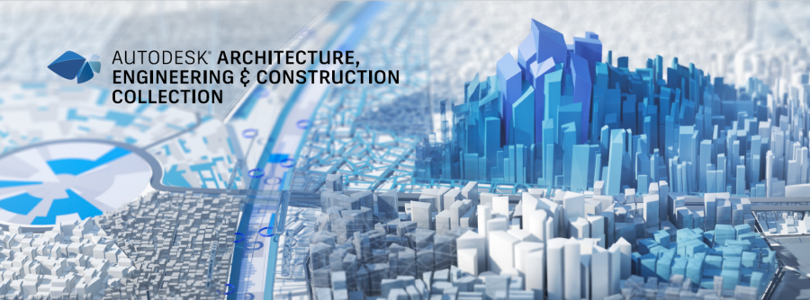
Connected Structural Design with the Autodesk Architecture Engineering and Construction Collection
The construction industry has seen a significant transformation in recent years with the adoption of new technologies and software. Structural engineering is no exception, as it plays a crucial role in the success of any construction project. Autodesk Architecture, Engineering, and Construction (AEC) Industry Collection is a suite of powerful software tools that enable structural engineers and fabricators to streamline their workflows and improve collaboration.
In this blog post, we will explore how Advance Steel, a software tool within the AEC Industry Collection, works with other applications such as Revit, Autodesk Docs, Robot Structural Analysis, Navisworks, and more to create a connected design process. We will also discuss the benefits of this approach for structural engineers and fabricators on construction projects.
How Does Advance Steel Work With Other Applications in the Collection?
With the AEC Industry Collection, structural engineers can create detailed designs, collaborate with architects and other stakeholders, and analyse their designs for efficiency and safety. Fabricators can use the software to create shop drawings and CNC files, and contractors can use it to manage construction projects and ensure that they stay on schedule and on budget.
Advance Steel is a software tool within the AEC Industry Collection that provides 3D modeling and detailing for steel structures. It is designed to streamline the design and fabrication process for steel structures, making it easier for engineers and fabricators to collaborate and ensure accuracy.
Advance Steel can be used to create detailed steel models in 3D, including connections, plates, and bolts. It also provides tools for creating drawings, bills of materials, and NC files for fabrication. With Advance Steel, engineers and fabricators can ensure that their designs are accurate and meet industry standards.
How Advance Steel works with other applications in the AEC Industry Collection
One of the key benefits of the AEC Industry Collection is that it provides a connected design process. This means that engineers and fabricators can use multiple software tools in the collection to streamline their workflows and ensure accuracy.
Here are some of the ways that Advance Steel works with other applications in the AEC Industry Collection:
Revit: Advance Steel can be used with Revit to create detailed steel models that include all of the necessary information for fabrication. Revit can also be used to create detailed architectural and MEP models, which can be linked to the steel model in Advance Steel for coordination.
Autodesk Docs: Autodesk Docs is a cloud-based document management platform that can be used to store and share project information. With Autodesk Docs, engineers and fabricators can collaborate on design files, RFIs, submittals, and more.
Robot Structural Analysis: Robot Structural Analysis is a software tool that can be used to analyse steel structures for safety and efficiency. With Robot Structural Analysis, engineers can perform finite element analysis (FEA) on their steel models to ensure that they meet industry standards.
Navisworks: Navisworks is a software tool that can be used for project coordination and clash detection. With Navisworks, engineers can import steel models from Advance Steel and other software tools to check for clashes and ensure.
- Other Applications: The AEC Industry Collection includes a wide range of other software tools that can be used in conjunction with Advance Steel. For example, Fabrication CADmep can be used to create detailed ductwork and piping models that can be linked to the steel model in Advance Steel for coordination.
Benefits of Connected Design for Structural Engineers and Fabricators
The connected design process enabled by the AEC Industry Collection provides several benefits for structural engineers and fabricators. Here are some of the key advantages:
Improved Collaboration: By using multiple software tools in the AEC Industry Collection, engineers and fabricators can collaborate more effectively. They can share design files, coordinate different aspects of the project, and ensure that everyone is working from the same information.
Streamlined Workflows: The connected design process also streamlines workflows by reducing the need for manual data entry and rework. Engineers and fabricators can move seamlessly between different software tools, and the data is automatically synchronised.
Increased Accuracy: By using software tools like Advance Steel, engineers and fabricators can ensure that their designs are accurate and meet industry standards. They can also perform analysis and simulations to ensure that the structure is safe and efficient.
Faster Time-to-Market: The connected design process enables faster time-to-market by reducing the time needed for design and fabrication. This can help construction companies stay on schedule and avoid delays.
Cost Savings: Finally, the connected design process can also lead to cost savings by reducing the need for rework and minimising errors. This can help construction companies stay on budget and avoid costly mistakes.
How Dynamo is Revolutionising Structural Design with Advance Steel and Revit
Dynamo is a visual programming tool that is transforming the way structural engineers and designers work. When combined with software tools like Advance Steel and Revit, it offers several benefits that can help streamline workflows and increase efficiency. In this article, we’ll explore the benefits of using Dynamo with Advance Steel and Revit for structural design.
- Automating Repetitive Tasks
One of the main benefits of using Dynamo with Advance Steel and Revit is the ability to automate repetitive tasks. For example, Dynamo can be used to automatically create connections between steel elements in Advance Steel based on predefined rules. This can save time and reduce errors, allowing engineers and designers to focus on more complex tasks.
- Enhanced Collaboration
Dynamo also improves collaboration between different teams involved in the structural design process. By using a visual programming language, designers and engineers can easily share scripts and workflows with other team members, regardless of their level of technical expertise. This helps to improve communication and ensures that everyone is working from the same information.
- Increased Accuracy and Quality
Using Dynamo with Advance Steel and Revit can help improve the accuracy and quality of structural designs. For example, Dynamo can be used to automatically calculate loads and reactions for a structure, or to optimize the size and shape of steel members. This can lead to more efficient and cost-effective designs, as well as better structural performance.
- Streamlined Workflows
Dynamo helps to streamline workflows by eliminating the need for manual data entry and reducing the potential for errors. By automating repetitive tasks and using a visual programming language, engineers and designers can move seamlessly between different software tools, saving time and reducing the potential for delays and mistakes.
- Improved Visualization
Finally, using Dynamo with Advance Steel and Revit can improve visualisation of the design. With Dynamo, engineers and designers can create complex geometry and parametric models, allowing for greater flexibility and better visualisation of the structure. This can help identify potential issues and make design decisions more effectively.
| Features | AutoCAD | Advance Steel | Revit |
|---|---|---|---|
| 2D Drafting | Comprehensive set of 2D drafting tools, including line, circle, polyline, arc, and text tools | Limited 2D drafting tools, including line, circle, and text tools | Limited 2D drafting tools, including line, circle, and text tools |
| 3D Modeling | Offers basic 3D modeling tools, including extrude, revolve, and loft tools | Offers more advanced 3D modeling tools, including parametric modeling tools and the ability to automatically generate steel elements | Offers advanced 3D modeling tools, including parametric modeling tools and the ability to create complex geometry |
| Steel Modeling | Limited steel modeling tools, including the ability to create steel elements manually | Offers more advanced steel modeling tools, including the ability to automatically generate steel elements and parametric modeling tools | Offers basic steel modeling tools, including the ability to create steel elements manually |
| Steel Detailing | Limited steel detailing tools, including the ability to create drawings of steel elements | Offers more advanced steel detailing tools, including the ability to automatically create part drawings, DXF and NC1 files, and CNC data export | Offers basic steel detailing tools, including the ability to create drawings of steel elements |
| Connection Design | No connection design tools | Offers comprehensive connection design tools, including the ability to create and analyze connections | Offers limited connection design tools, including the ability to create basic connections |
| Structural Analysis | No structural analysis tools | Offers more advanced structural analysis tools, including the ability to analyze and optimize steel structures | Offers basic structural analysis tools, including the ability to analyze and check steel structures |
| Fabrication | No fabrication tools | Offers comprehensive fabrication tools, including the ability to create shop drawings, CNC data export, and automatic creation of bills of materials | Limited fabrication tools, including the ability to create shop drawings and bills of materials |
| Collaboration | Offers basic collaboration tools, including the ability to share drawings and collaborate on design | Offers more advanced collaboration tools, including the ability to connect to Dynamo and synchronize with Revit models | Offers advanced collaboration tools, including the ability to connect to Dynamo and synchronize with Advance Steel models |
AutoCAD offers a comprehensive set of 2D drafting tools, including line, circle, polyline, arc, and text tools. It also offers basic 3D modeling tools, such as extrude, revolve, and loft tools. However, it has limited steel modeling and detailing tools, connection design, structural analysis, and fabrication tools.
Advance Steel offers more advanced steel modeling and detailing tools than AutoCAD. It can automatically generate steel elements, create part drawings, DXF and NC1 files, and export CNC data. It also has comprehensive connection design and fabrication tools. Advance Steel is specifically designed for steel design and fabrication, making it a powerful tool for structural engineers and steel fabricators.
Revit offers advanced 3D modeling tools and basic steel modeling and detailing tools. It can connect to Dynamo and synchronise with Advance Steel models, which makes it an excellent tool for collaboration with architects and other stakeholders in the building design process.
In summary, the choice between AutoCAD, Advance Steel, and Revit depends on the specific needs of the project and the users. AutoCAD is a general-purpose drafting tool, while Advance Steel is specifically designed for steel design and fabrication, and Revit is an excellent tool for collaboration and building design coordination.
Analysing Structural Designs: Advance Steel Vs Revit Vs Robot Structural Analysis
| Feature | Advance Steel | Revit | Robot Structural Analysis |
|---|---|---|---|
| Finite Element Analysis | Yes | Yes | Yes |
| Static Analysis | Yes | Yes | Yes |
| Dynamic Analysis | Yes | No | Yes |
| Buckling Analysis | Yes | No | Yes |
| Nonlinear Analysis | Yes | No | Yes |
| Eigenvalue Analysis | Yes | No | Yes |
| Response Spectrum Analysis | Yes | No | Yes |
| Pushover Analysis | Yes | No | Yes |
| Design Optimization | Yes | No | Yes |
| Steel Connections Analysis | Yes | No | Yes |
| Concrete Analysis | No | Yes | Yes |
| Wood Analysis | No | Yes | Yes |
| Masonry Analysis | No | Yes | Yes |
| Design Code Compatibility | Multiple | Multiple | Multiple |
| Integration with Other Tools | Revit, Dynamo | Navisworks | Revit, Navisworks |
Overall, all three software products offer FEA capabilities for structural analysis, including static analysis and finite element analysis. However, Robot Structural Analysis offers more advanced analysis options such as dynamic analysis, buckling analysis, nonlinear analysis, eigenvalue analysis, response spectrum analysis, and pushover analysis. Advance Steel offers the ability to analyze steel connections, while Revit offers analysis options for concrete, wood, and masonry.
In terms of design code compatibility, all three software products support multiple design codes. Additionally, Revit and Robot Structural Analysis can integrate with Navisworks for clash detection and coordination, while Advance Steel and Revit can connect with Dynamo for automation and optimization of structural designs.
Structural Design Collaboration with the AEC Collection
Structural steel design collaboration is a critical aspect of any construction project. Autodesk AEC Collection offers several collaboration tools, including Navisworks and Autodesk Docs, that can help structural engineers collaborate effectively throughout the design and construction process.
Navisworks is a project review and coordination tool that allows engineers and designers to combine models and data from various sources, including Advance Steel and Revit. Navisworks can help identify and resolve potential design conflicts, allowing for more efficient construction planning and reducing the risk of costly errors during construction.
Autodesk Docs is a cloud-based collaboration tool that allows team members to share and access project information, documents, and models from anywhere and on any device. With Autodesk Docs, structural engineers can collaborate in real-time with other team members, including architects, contractors, and owners. The tool can also help track changes, versioning, and approval workflows, ensuring that all team members are working on the latest version of the project documents.
Connected Structural Design
The Autodesk Architecture Engineering and Construction Collection is a powerful suite of software programs that can help architects create better designs and collaborate more effectively with other professionals in the construction industry. By using programs such as Revit, Navisworks, and Docs, architects can create digital models of buildings and share them with other stakeholders, streamlining the design process and reducing errors. By collaborating with MEP/HVAC, Structural and Civil engineers and designers, architects can ensure that their designs are not only visually appealing but also practical and functional, resulting in better-performing buildings that meet safety and regulatory requirements.
Ready to get your Design Connected?
Discover how Autodesk Architecture Engineering and Construction Collection can streamline your workflow, increase productivity, and optimise your design process.
Get up to 20% Off Software or Services!
Contact us to find out how much money you can save on software, training or other services. Fill out the form below, by live chat, phone or email.
P: 1800 490 514 | E: [email protected]
Connected Design with Architecture Engineering and Construction Collection
Click a link below to learn more about Connected Design using the Autodesk Product Design & Manufacturing Collection
