1800 490 514 [email protected]

Automate your Design Processes with Autodesk Vault

Autodesk Vault Autodesk Vault Basic,Vault Professional, available on-premise or pay by the month in the cloud

5 Powerful Ways to Automate your Design Processes with Autodesk Vault

Speed up Autodesk AutoCAD, Inventor CAD/CAM and data management workflows .

Design automation is the use of software to automate repetitive tasks in the design process. This can save time and money by freeing up engineers to focus on more creative and strategic work. Autodesk Vault is a product data management (PDM) software that includes a number of features for design automation.

Autodesk Vault is available on-premise or on cloud

Benefits of design automation in Autodesk Vault

Design automation in Autodesk Vault can also provide a number of other benefits, including:

  • Increased accuracy: By automating repetitive tasks, engineers can reduce the risk of errors.
  • Improved efficiency: Engineers can spend more time on creative and strategic work, and less time on administrative tasks.
  • Improved collaboration: Autodesk Vault can help engineers to collaborate more effectively by providing a central repository for design data.
  • Improved compliance: Autodesk Vault can help organizations to comply with industry regulations by providing a secure and auditable way to store design data.

If you are looking for ways to save time and money in your design process, then design automation in Autodesk Vault is a great option. By automating repetitive tasks, you can free up your engineers to focus on more creative and strategic work. This can lead to increased accuracy, efficiency, collaboration, and compliance.

Copy Design

One of the most common tasks in the design process is copying existing designs. This can be a time-consuming and error-prone process. Automate the copy design process by creating a new design that is a copy of an existing design. This can be done with a single click of a button.

Automatic Numbering Schemes

Another common task in the design process is assigning part numbers to parts. This can also be a time-consuming and error-prone process. Automate the part numbering process by creating a custom numbering scheme. This can ensure that part numbers are assigned consistently and correctly.

Whats New in Autodesk Vault 2024 Job Processor Copy Folder Structure Setup a new project quickly Start with a known folder structure Users can create a project folder from a template or previous folder structure Copy Folder Structure permissions and Properties

Revision Control

As designs evolve, it is important to track changes. Automate the revision control process by creating a revision history for each design. This can help engineers to track changes and to revert to previous versions of designs if necessary.

Version Control

In addition to revision control, Autodesk Vault can also automate the version control process. This means that multiple versions of a design can be stored in Vault and that changes can be tracked between versions. This can help engineers to collaborate on designs and to track the progress of designs over time.

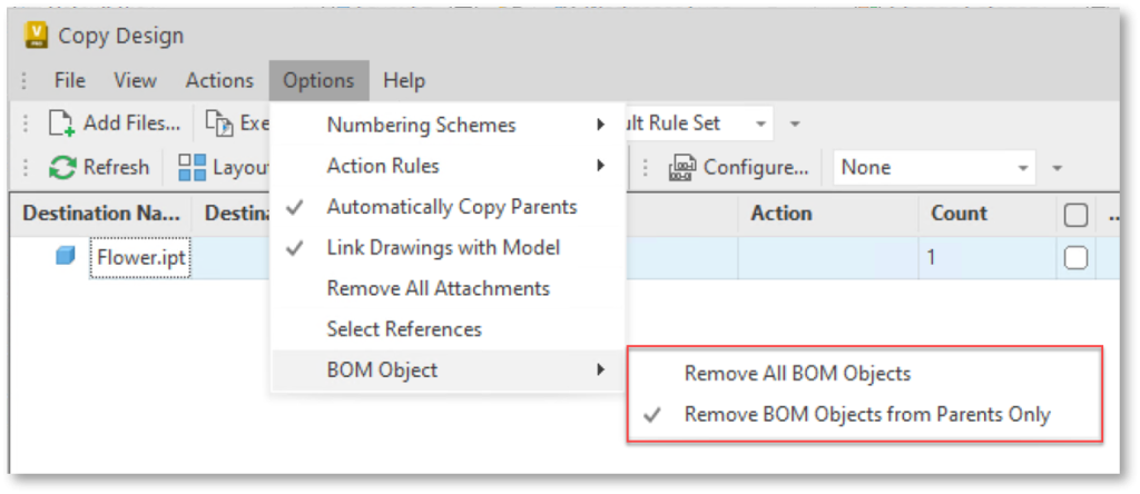
Whats New in Autodesk Vault 2024 Job Processor Copy Design BOM Enhancements Newly copied parts can be assigned to an Item immediately after Copy Design is executed Copy Design updates the BOM information in part files without having to open them in Inventor first. Autodesk Vault Professional Training Course

Job Processor

The Job Processor is a powerful tool that can be used to automate a variety of design tasks. This includes tasks such as generating bills of materials, creating drawings, and submitting designs for manufacturing. The Job Processor can be used to automate repetitive tasks, freeing up engineers to focus on more creative and strategic work.

JP Pro is a power job processor built on Autodesk Vault Professional that allows you to automate publishing of files, email notifications, synchronisation and much more..

JP Pro for Autodesk Vault Professional is an advanced job processor to automate publishing on files on-demand or automatically on change state, bom export, email notifications and more.
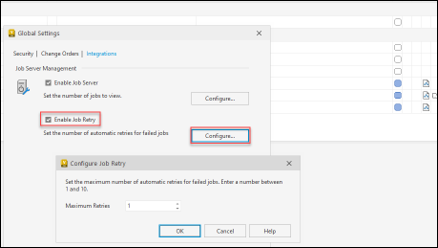
Whats New in Autodesk Vault 2024 Job Processor Job Processor Apply retry strategy to visualization and custom jobs to reduce administration and user disruption to re-submit such jobs manually. Automatic Retry capability for failed Job Specify retry strategy between 1 and 10 attempts The Job Processor will retry the failed jobs automatically without manual intervention

ERP Integration

In addition to the 5 ways to automate using Vault, Vault can be integrated with a variety of enterprise resource planning (ERP) systems. This allows engineers to share data with other departments in the organization, such as manufacturing and sales. This can help to improve communication and collaboration between departments, and to ensure that everyone is working with the latest information.

Ready to Automate?

Design automation is a powerful tool that can save time and money for AutoCAD and Inventor users. Autodesk Vault includes a number of features for design automation, including copy design automation, automatic numbering schemes, revision control, version control, job processor and ERP integration. These features can help engineers to automate repetitive tasks, freeing up time for more creative and strategic work.

Contact us on 1800 490 514, [email protected] or fill out the contact us form below.

Design Automation

VIEW MORE

Design Automation with Inventor: Boosting Efficiency and Productivity

Autodesk Inventor Professional 3D mechanical CAD software

Design Automation with Inventor: Boosting Efficiency and Productivity

Autodesk Inventor iLogic design automation services and training

In today’s fast-paced world, businesses are constantly seeking innovative ways to streamline their design processes and enhance productivity. One such solution is design automation, which empowers engineers and designers to automate repetitive tasks and focus on more complex aspects of their projects. In this blog, we will delve into the world of design automation with Autodesk Inventor, exploring the utilisation of iLogic, macros, the Inventor API, and Forge Design Automation. Let’s embark on this journey towards increased efficiency and productivity!

Leveraging iLogic for Design Automation

iLogic is a powerful feature integrated into Autodesk Inventor that allows users to automate design processes by defining rules and logic. By creating iLogic rules, designers can automate repetitive tasks, customise designs based on specific parameters, and streamline the overall design workflow. This section will discuss the fundamentals of iLogic, provide practical examples, and showcase its potential for design automation.

Streamlining Design with Macros

Macros offer another excellent way to automate design processes in Autodesk Inventor. A macro is a script or set of commands that can be executed to perform repetitive tasks automatically. With macros, designers can automate complex sequences of actions, such as generating parts, assemblies, or drawings, significantly reducing the time and effort required. This section will explore the basics of using macros, highlight their benefits, and provide code examples for practical implementation.

Extending Functionality with the Inventor API

The Inventor API (Application Programming Interface) provides developers with a powerful toolset to extend the capabilities of Autodesk Inventor. By utilizing the API, designers can create custom applications, add-ins, and scripts that automate specific design tasks or enhance existing functionalities. This section will introduce the Inventor API, discuss its key features, and demonstrate how it can be leveraged to automate repetitive design processes effectively.

Harnessing the Power of Autodesk Platform Services

Autodesk Platform Services (aka Forge) is a cloud-based platform that enables the automation of design and engineering workflows at scale. By integrating Forge Design Automation with Autodesk Inventor, businesses can automate time-consuming tasks, reduce manual errors, and improve collaboration among teams. This section will provide an overview of Forge Design Automation, discuss its benefits, and explore real-world examples of how it can enhance design automation processes.

Automating Revit with JP Pro

JP Pro is a power job processor built on Autodesk Vault Professional that allows you to automate publishing of files, email notifications, synchronisation and much more..

Ready to Automate?

Contact us on 1800 490 514, [email protected] or fill out the contact us form below.

Design Automation

VIEW MORE

Connected MEP Design with Autodesk Product Design & Manufacturing Collection

Connected MEP Design Moving at the Speed of Business
Design Consulting Product Design Manufacturing Collection Moving at the Speed of Business

Connected MEP Design with Autodesk Product Design & Manufacturing Collection

Streamlining MEP Design with Autodesk: An In-Depth Look at AutoCAD MEP and Inventor's Tools and Benefits

MEP (mechanical, electrical, and piping) design is an essential part of building construction, and Autodesk’s Product Design and Manufacturing Industry Collection provides software tools to simplify and streamline the MEP design process. In this blog post, we’ll explore how Autodesk’s AutoCAD MEP and Inventor can be used for efficient and accurate MEP design

Using AutoCAD MEP for MEP Design

AutoCAD MEP is a powerful software tool specifically designed for MEP industry professionals. It comes equipped with a range of tools that make MEP design more efficient, including mechanical, electrical, and plumbing content, tool palettes, space coordination, electrical circuiting, and data extraction. These tools make it easy to create, edit, and share MEP designs with precision and accuracy

Use AutoCAD MEP to design HVAC systems and extend capabilities with Revit MEP (BIM) and cadMEP, ESTmep and CAMduct (Fabrication)

Using Autodesk Inventor for MEP Design

Autodesk Inventor is a 3D mechanical design software tool that can be used for MEP design. Its tube and pipe routing features, assembly environment, XREF, and AnyCAD features make it ideal for designing and analysing piping systems. The software allows for the creation of intelligent 3D models that can be used for interference checking, stress analysis, and simulation, providing MEP professionals with the necessary tools to streamline their design process.

Benefits of Using Autodesk's Product Design and Manufacturing Industry Collection

Using Autodesk’s Product Design and Manufacturing Industry Collection provides many benefits for MEP design. It saves time, improves accuracy, and ensures compliance with industry standards. With this software collection, MEP professionals have access to a suite of tools that can be used for 2D and 3D design, simulation, and analysis. Additionally, the software integrates with other Autodesk products, allowing for seamless collaboration between teams.

Importing DWG Files into AutoCAD MEP and Inventor

Both AutoCAD MEP and Inventor allow for the import of 2D and 3D DWG files. In AutoCAD MEP, you can import 2D DWG files using the “Insert” command. You can also import 3D DWG files and use them as a reference to create a new MEP model. In Inventor, you can import 2D DWG files using the AnyCAD feature. This feature allows you to link the 2D DWG file to your Inventor model, allowing you to update your design in real-time.

XREFing an Inventor Model into AutoCAD MEP

In addition to importing DWG files, you can also XREF an Inventor model into AutoCAD MEP. This feature allows you to bring in a 3D model created in Inventor and use it as a reference for your AutoCAD MEP model. By doing so, you can ensure that your MEP design is accurate and coordinated with other building systems.

Conclusion

In conclusion, Autodesk’s Product Design and Manufacturing Industry Collection provides MEP professionals with a suite of tools that can be used to streamline their design process. AutoCAD MEP and Inventor are two software tools that provide MEP professionals with a range of features, including mechanical, electrical, and plumbing content, tube and pipe routing, assembly environment, XREF, AnyCAD, and more.

You can also check out our Fabrication page to learn more about Fabrication workflows for MEP.

Ready to get your MEP Design Connected?

Discover how Autodesk Product Design & Manufacturing Collection can streamline your workflow, increase productivity, and optimise your design process. 

Get up to 20% Off Software or Services!

Contact us to find out how much money you can save on software, training or other services. Fill out the form below, by live chat, phone or email.

P: 1800 490 514 |  E: [email protected]

Connected Design

Connected MEP Design Moving at the Speed of Business

Connected Design with Product Design & Manufacturing Collection

Click a link below to learn more about Connected Design using the Autodesk Product Design & Manufacturing Collection 

VIEW MORE

Connected Mechanical Design with Autodesk Product Design & Manufacturing Collection

Connected Mechanical Design 2 Moving at the Speed of Business
Design Consulting Product Design Manufacturing Collection Moving at the Speed of Business

Connected Mechanical Design with Autodesk Product Design & Manufacturing Collection

Streamlining Mechanical Design with Product Design & Manufacturing Collection: A Guide to Connecting Autodesk Inventor, Fusion 360, AutoCAD, and AutoCAD Mechanical

Mechanical design is an intricate process that requires the use of multiple software tools. Each software tool has its unique features, which are essential for creating a functional design. The Product Design & Manufacturing Collection from Autodesk brings together all the necessary tools for mechanical design. This collection includes Autodesk Inventor, Fusion 360, AutoCAD, and AutoCAD Mechanical. By using these tools together, mechanical design becomes more streamlined and efficient. In this guide, we will explore the benefits of using these tools in conjunction with each other and provide a step-by-step process on how to connect them for maximum efficiency.

Overview of Product Design & Manufacturing Collection

The Product Design & Manufacturing Collection from Autodesk is a comprehensive collection of software tools that are designed to streamline the product design process. The collection includes Autodesk Inventor, Fusion 360, AutoCAD, and AutoCAD Mechanical. These tools work together seamlessly, allowing engineers and designers to collaborate on projects and share data across platforms. By using these tools together, teams can reduce errors, improve accuracy, and speed up the design process.

The Benefits of Using Autodesk Inventor, Fusion 360, AutoCAD, and AutoCAD Mechanical Together

The benefits of using Autodesk Inventor, Fusion 360, AutoCAD, and AutoCAD Mechanical together are numerous. First, the tools provide a comprehensive set of features that cover all aspects of mechanical design, from 3D modeling to simulation to manufacturing. Second, the tools are designed to work together seamlessly, allowing teams to collaborate on projects and share data across platforms. Third, the tools are constantly updated and improved, ensuring that users always have access to the latest features and functionality.

Connecting Autodesk Inventor, Fusion 360, AutoCAD, and AutoCAD Mechanical

To connect Autodesk Inventor, Fusion 360, AutoCAD, and AutoCAD Mechanical, follow these steps:

Install all the software tools from the Product Design & Manufacturing Collection on your computer.

Open Autodesk Inventor and create a new part or assembly.

From the menu bar, select “Manage” and then select “Import/Export.”

From the dropdown menu, select the file format you wish to use (e.g., DWG, DXF, IGES).

Select the file you wish to import and click “Open.”

The file will be imported into Autodesk Inventor, and you can start working on it.

Using Autodesk Inventor, Fusion 360, AutoCAD, and AutoCAD Mechanical for Mechanical Design

Autodesk Inventor is a powerful 3D CAD software that is used for mechanical design. It allows designers to create 3D models of parts and assemblies, perform simulations, and generate documentation. Fusion 360 is a cloud-based CAD/CAM software that allows designers and engineers to collaborate on projects in real-time. AutoCAD is a 2D CAD software that is used for creating detailed drawings, and AutoCAD Mechanical is a 3D CAD software that is used for mechanical design.

Ready to Get Connected?

Save up to 20% on Autodesk Software and Services

Unlocking the Power of AnyCAD: Combining Autodesk Inventor, Fusion 360, and AutoCAD Mechanical for Seamless Mechanical Design

AnyCAD in Autodesk Product Design & Manufacturing Collection lets you transfer 3D models between different software platforms effortlessly, making collaboration on complex projects easier. AnyCAD enables you to link Autodesk Inventor, Fusion 360, and AutoCAD Mechanical to create an integrated mechanical and electrical design with automatic updates. The 2D detailing in AutoCAD Mechanical benefits from AnyCAD’s ability to import the Inventor model, maintaining a single source of truth for design data and reducing the risk of errors.

Front page Moving at the Speed of Business

AnyCAD and DWG Files

Autodesk Inventor and AutoCAD are powerful design tools for 3D and 2D design, respectively. With AnyCAD, users can import AutoCAD DWG files into Inventor and work with both 2D and 3D geometry. AnyCAD eliminates the need for manual conversions and allows for faster and more accurate design changes. It also enables users to work with annotations and other design details in both environments, improving collaboration and communication between stakeholders. Overall, AnyCAD streamlines the design process, making it more efficient and accurate.

inventor 2021 revit to inventor anycad 11 1024x1024 1 Moving at the Speed of Business

Combining all Designs from Fusion 360 and AutoCAD Mechanical into Autodesk Inventor

The Product Design & Manufacturing Collection from Autodesk offers a suite of powerful tools for designing and manufacturing products. One of the major benefits of this collection is the ability to seamlessly integrate designs from different software platforms, such as Autodesk Inventor, Fusion 360, and AutoCAD Mechanical. In this post, we’ll explore how to combine all designs from Fusion 360 and AutoCAD Mechanical into Autodesk Inventor.

Importing Fusion 360 designs

To import a Fusion 360 design into Inventor using Anycad, you first need to export the design as a STEP file from Fusion 360. In Fusion 360, select the design you want to export, go to the File menu, and select Export. Choose the STEP file format and save the file.

Next, open an Inventor assembly and go to the Anycad tab. Click on the Import command and select the exported STEP file. The Fusion 360 design will now be imported into the Inventor assembly, where you can combine it with other designs.

Importing AutoCAD Mechanical designs

To import an AutoCAD Mechanical design into Inventor using Anycad, you need to export the design as a DWG file from AutoCAD Mechanical. In AutoCAD Mechanical, select the design you want to export, go to the File menu, and select Save As. Choose the DWG file format and save the file.

Next, open an Inventor assembly and go to the Anycad tab. Click on the Import command and select the exported DWG file. The AutoCAD Mechanical design will now be imported into the Inventor assembly, where you can combine it with other designs.

Combining all designs in Inventor

Once you’ve imported the designs from Fusion 360 and AutoCAD Mechanical into Inventor, you can start combining them. You can use the assembly tools in Inventor to mate and constrain the different components, creating a complete 3D model. You can also use the drawing tools in Inventor to create 2D drawings and detailing.

Combining all Designs into AutoCAD Mechanical

When using the Product Design & Manufacturing Collection, it’s possible to combine the strengths of different software programs to create a more comprehensive mechanical design workflow. One example of this is using Autodesk Inventor to create a 3D mechanical model, which could have a Fusion 360 model linked into it.

Once the 3D model is complete, it can be imported into AutoCAD Mechanical to further refine the design and create detailed 2D drawings. AutoCAD Mechanical offers a range of powerful tools for creating mechanical drawings, including the ability to create and edit mechanical symbols, automate common tasks, and easily generate bills of materials.

To import the Inventor model into AutoCAD Mechanical, simply use the “Insert” command to bring the 3D model into the 2D workspace. Once the model is in place, you can use AutoCAD Mechanical’s powerful annotation tools to add dimensions, notes, and other details to your drawings.

It’s worth noting that AutoCAD Mechanical also has a range of built-in tools for working with Inventor files directly, including the ability to import Inventor assemblies and parts directly into the software. This can be a great way to leverage existing Inventor designs and incorporate them into your AutoCAD Mechanical workflows.

Overall, the combination of Inventor, Fusion 360, and AutoCAD Mechanical offers a powerful suite of tools for mechanical design and detailing. By leveraging the strengths of each software program, designers can create comprehensive mechanical designs and detailed 2D drawings with greater efficiency and accuracy.

Ready to get your Mechanical Design Connected?

Discover how Autodesk Product Design & Manufacturing Collection can streamline your workflow, increase productivity, and optimise your design process. 

Get up to 20% Off Software or Services!

Contact us to find out how much money you can save on software, training or other services. Fill out the form below, by live chat, phone or email.

P: 1800 490 514 |  E: [email protected]

Connected Design

Connected Mechanical Design 2 Moving at the Speed of Business

Connected Design with Product Design & Manufacturing Collection

Click a link below to learn more about Connected Design using the Autodesk Product Design & Manufacturing Collection 

VIEW MORE

Connected Design with Autodesk Product Design & Manufacturing Collection

Product Design & Manufacturing Collection IC Commercial New Single-user ELD Annual Subscription
Design Consulting Product Design Manufacturing Collection Moving at the Speed of Business

Connected Design with Autodesk Product Design & Manufacturing Collection

Connecting Autodesk Inventor with Other Software Tools for Efficient Design

Are you looking for ways to streamline your product design and manufacturing process? Autodesk Product Design & Manufacturing Collection which includes Autodesk Inventor, a powerful 3D modelling software, can be a game-changer for your business. Not only can Inventor help you create complex designs with ease, but it can also connect with other Autodesk software tools for a more efficient and integrated design process.

Here’s how Product Design & Manufacturing Collection and Inventor can connect with other Autodesk software tools to improve your design workflow:

Connected Design with Product Design & Manufacturing Collection

Inventor can be used in conjunction with other Autodesk software tools such as Revit, 3ds Max, and AutoCAD. This “connected design” approach allows for seamless data exchange between software applications, improving collaboration and reducing the risk of errors and delays.

Using Inventor and AutoCAD to improve Design and Collaboration

Inventor and AutoCAD can be used together to create 2D drawings of 3D models. This integration streamlines the design process and allows for quick changes to be made to drawings as the design evolves.

Collaboration in Navisworks

Models can be imported into Navisworks for simulation and analysis. This integration allows designers to evaluate the performance of their designs and identify potential issues before production begins.

Navisworks Factory Moving at the Speed of Business
Editing Properties in Vault

Connected Design with 3ds Max

Export 3D models to 3ds Max for high-quality rendering and visualization. This integration allows designers to create photorealistic images and animations of their designs, making it easier to communicate their vision to stakeholders and customers.

Autodesk Revit

Connecting Product Design & Manufacturing Collection to Revit

Inventor can import Revit models to create detailed designs for mechanical and electrical components. Revit models can also be exported to Inventor for further refinement.

Revit interoperability Moving at the Speed of Business

Autodesk Shared Views: Collaborate Easily with Stakeholders

Autodesk Shared Views is a cloud-based tool that enables users to share their designs and models with stakeholders in real-time. It simplifies the review process by allowing users to share a link to the Shared View, where reviewers can access the design directly in their browser. Shared Views supports multiple reviewers and provides markup tools for collaboration. The tool also includes version control features for tracking changes and viewing previous versions. Being cloud-based, Shared Views requires no software or hardware installation, making it accessible from any device with an internet connection.

How Autodesk Inventor Helps You Achieve BIM Interoperability

Autodesk Inventor simplifies BIM workflows and enhances collaboration with other stakeholders by providing BIM interoperability tools. These tools allow you to create, import and export BIM data in various formats, enabling you to work more efficiently with software like Revit and Navisworks. Inventor’s BIM Content Creation, BIM Content Import, BIM Project Review and BIM-to-Fabrication tools provide accurate and consistent designs. These tools can be used in conjunction with the Product Design and Manufacturing Industry Collection, which includes additional software tools. Start using Inventor’s BIM interoperability tools today to streamline your workflow and deliver better projects.

Ready to Get Connected?

Save up to 20% on Autodesk Software and Services

Revolutionizing Electronics Design: How Autodesk Inventor's PCB Interoperability Tools are Changing the Game

Autodesk Inventor is a powerful CAD software that offers a range of advanced features for mechanical and electrical design. One of the most valuable features for electronic designers is the ability to work with printed circuit boards (PCBs) directly in the software. With Autodesk Inventor’s PCB interoperability tools, users can streamline their design process and create more accurate designs.

Inventor’s PCB Interoperability Tools

Inventor offers a suite of tools for working with PCBs, including:

  • ECAD-MCAD Collaboration
  • PCB layout import
  • Design rule checking
  • Export to Manufacturing

Additionally, Inventor’s ability to import and view PCB layouts from other software tools enables designers to work with existing designs and make any necessary changes in a 3D environment. This feature saves time and improves accuracy.

Finally, Inventor’s comprehensive design rule checking tool ensures that the design meets industry standards and identifies any potential errors before the manufacturing process. This feature reduces the risk of costly errors and ensures that the design is accurate and ready for production.

Product Design & Manufacturing Collection Connected Matrix

SoftwareDescriptionFile TypeCommandImport/ExportLink
Inventor3D mechanical design software used for creating detailed product designs and engineering documentationIPT, IAMOPEN, MODEL, DRAWING, PUBLISHImport: DWG, DXF, STEP, IGES, SAT, CATIA, SolidWorks, Pro/E, NXExport: DWG, DXF, STEP, IGES, SAT, CATIA, SolidWorks, Pro/E, NX
AutoCAD2D and 3D computer-aided design software used for creating blueprints, schematics, and modelsDWG, DXF, DWFDRAWING, MODEL, VIEW, PLOTImport: DWG, DXF, DWF, PDF, STEP, SAT, IGES, STLExport: DWG, DXF, DWF, PDF, STL, OBJ, FBX
Fusion 360Integrated CAD, CAM, and CAE software used for product development and manufacturingF3D, IPT, IAMOPEN, MODEL, DRAWING, CAMImport: DWG, DXF, STEP, IGES, SAT, SolidWorks, Pro/E, NXExport: DWG, DXF, STEP, IGES, SAT, SolidWorks, Pro/E, NX
Alias AutoStudioIndustrial design software used for creating and visualizing product designsOBJ, STLOPEN, MODEL, RENDERImport: IGES, STEP, STL, OBJ, SolidWorks, CATIA, Pro/EExport: IGES, STEP, STL, OBJ, SolidWorks, CATIA, Pro/E
NavisworksProject review software used for 3D coordination, model analysis, and clash detectionNWD, NWFOPEN, APPEND, EXPORT, PUBLISHImport: DWG, DWF, DGN, IFC, SKP, FBX, 3DS, OBJExport: DWF, DWFx, NWC, NWF, FBX, 3DS, OBJ
      
HSMWorksIntegrated CAM software used for programming CNC machinesIPT, IAMSETUP, TOOLPATH, POSTImport: DWG, DXF, STEP, IGES, SAT, SolidWorks, Pro/E, NXExport: DWG, DXF, STEP, IGES, SAT, SolidWorks, Pro/E, NX
Nastran In-CADFinite element analysis (FEA) software used for simulating and analyzing product designsNAS, OP2OPEN, ANALYSIS, RESULTSImport: IPT,

Interoperability between design and analysis software

Import/Export: Inventor supports a variety of file formats for import and export, including STEP, IGES, and SAT. This flexibility allows for easy data exchange between Inventor and other software tools, improving collaboration and reducing errors.

Collaboration

By connecting Inventor with other Autodesk software tools, designers can create complex designs with ease, reduce errors and delays, and streamline the design process. With improved collaboration and data exchange, the product design and manufacturing process can be more efficient and cost-effective.

In conclusion, Autodesk Inventor is a powerful tool that can be used in conjunction with other Autodesk software tools to improve the design workflow. By following the tips outlined in this article, you can optimize your design process, reduce errors and delays, and create high-quality designs that meet your business needs.

Ready to get your Design Connected?

Discover how Autodesk Product Design & Manufacturing Collection can streamline your workflow, increase productivity, and optimise your design process. 

Get up to 20% Off Software or Services!

Contact us to find out how much money you can save on software, training or other services. Fill out the form below, by live chat, phone or email.

P: 1800 490 514 |  E: [email protected]

Connected Design

Design Consulting Product Design Manufacturing Collection Moving at the Speed of Business

Connected Design with Product Design & Manufacturing Collection

Click a link below to learn more about Connected Design using the Autodesk Product Design & Manufacturing Collection 

VIEW MORE

Connected Electrical Design with Autodesk Product Design & Manufacturing Collection

Connected Electrical Design Moving at the Speed of Business
Design Consulting Product Design Manufacturing Collection Moving at the Speed of Business

Connected Electrical Design with Autodesk Product Design & Manufacturing Collection

Autodesk Inventor and AutoCAD Electrical are two of the most popular software applications used in engineering design, particularly in electrical and electronic design automation. While each has its own strengths, combining these two powerful tools can lead to even greater design efficiency and productivity. In this article, we will explore how Autodesk Inventor and AutoCAD Electrical work together, focusing on the EMX project, syncing files, and how they can be combined with Fusion 360 for advanced PCB design.

Autodesk Inventor and AutoCAD Electrical: Combining Forces for Better Schematic Design

Introduction to Autodesk Inventor and AutoCAD Electrical

Autodesk Inventor is a 3D modeling software used primarily for mechanical engineering design. It allows users to create precise 3D models of mechanical parts, assemblies, and even entire machines. On the other hand, AutoCAD Electrical is a specialized software used for electrical engineering design. It provides a comprehensive set of tools for creating and modifying electrical control systems, wiring diagrams, and other related documentation.

The EMX Project: Enhancing Design Efficiency and Productivity

The EMX Project is an add-on for AutoCAD Electrical that enables users to create 3D representations of their electrical schematics in Autodesk Inventor. This makes it possible to visualize the electrical components in 3D space, making it easier to detect potential design issues before fabrication. The EMX project also allows users to import Inventor models into AutoCAD Electrical, giving them a more realistic representation of the actual components used in their designs.

Syncing Files Between Inventor and AutoCAD Electrical

Another advantage of using Autodesk Inventor and AutoCAD Electrical together is the ability to sync files between the two applications. This allows users to transfer 3D electrical harness models from Inventor to Electrical or vice versa, as well as easily update changes made in one application to the other. This seamless integration not only saves time but also ensures accuracy and consistency in design documentation.

Combining with Fusion 360: Taking PCB Design to the Next Level

Fusion 360 is a cloud-based CAD/CAM platform that allows users to collaborate on projects in real-time. It integrates with both Autodesk Inventor and AutoCAD Electrical, enabling users to bring their schematic designs into the 3D modeling environment of Fusion 360 for more advanced PCB design. This integration streamlines the design process and helps eliminate errors by providing a seamless workflow from schematic design to PCB layout and manufacturing.

How to Get Started with Autodesk Inventor and AutoCAD Electrical

To get started with Autodesk Inventor and AutoCAD Electrical, users need to have a basic understanding of electrical engineering principles and practices. They also need to have access to both software applications, as well as the EMX Project add-on for AutoCAD Electrical. Additionally, users can benefit from online training resources, tutorials, and forums provided by Autodesk to help them master the software.

Connected Electrical Design AutoCAD Electrical Schematics - Connected Electrical Design

Revolutionizing Electronics Design: How Autodesk Inventor's PCB Interoperability Tools are Changing the Game

Autodesk Inventor is a powerful CAD software that offers a range of advanced features for mechanical and electrical design. One of the most valuable features for electronic designers is the ability to work with printed circuit boards (PCBs) directly in the software. With Autodesk Inventor’s PCB interoperability tools, users can streamline their design process and create more accurate designs.

Picture2 Moving at the Speed of Business

Ready to Get Connected?

Save up to 20% on Autodesk Software and Services

How to Achieve Connected Design with Autodesk Inventor and Eagle (Fusion 360)

Look no further than Autodesk’s connected design solution between Inventor and Eagle. This powerful combination allows for seamless collaboration between mechanical and electrical design teams. Autodesk Eagle, now a part of Fusion 360, is a popular PCB design tool that offers a range of powerful features to create schematics, layout designs, and manufacturing outputs. By integrating Eagle with Inventor, designers can easily incorporate PCBs into their mechanical assemblies and optimize the fit and function of their designs. 

One key advantage of using Inventor and Eagle together is the ability to maintain a “single source of truth” for your design data. With the integration, design changes in one tool can be automatically propagated to the other, reducing the risk of errors and ensuring consistency across the design process. Another benefit of this connected design approach is the ability to visualize the PCB and its components in a 3D mechanical assembly context.

This allows designers to check for potential interferences, optimize the placement of the PCB and its components, and ultimately achieve a more efficient and cost-effective design. To get started with connected design between Inventor and Eagle, simply import your Eagle board file into Inventor.

From there, you can place the PCB into your assembly and start working on the integration with your mechanical components. Changes made to the PCB in Eagle will be reflected in Inventor, and vice versa.

Inventor’s PCB Interoperability Tools

Inventor offers a suite of tools for working with PCBs, including:

ECAD-MCAD Collaboration

This tool allows electrical and mechanical designers to work together seamlessly by importing 3D models of the PCB into Inventor. This tool eliminates the need for physical prototypes and enables designers to test the fit of the PCB in the mechanical assembly.

PCB layout import

Inventor can import and view PCB layouts from other software tools such as Eagle, Altium, and OrCAD. This feature allows designers to view their designs in a 3D environment and make any necessary changes before finalizing the design.

 Design rule checking

Inventor offers a comprehensive design rule checking tool that allows designers to check their PCB designs against a set of predefined rules. This feature ensures that the design meets industry standards and helps identify any potential errors before the manufacturing process.

Export to Manufacturing

Once the design is complete, Inventor can export the PCB design to the manufacturing process. This feature ensures that the design is accurate and ready for production.

Seamless Integration: How Autodesk Inventor and Fusion 360 Work Together for Streamlined PCB Design

https://www.autodesk.com/redshift/pcb-design-with-fusion-360/Autodesk Inventor and Fusion 360 are both powerful design tools that can be used for a wide range of applications. While Inventor is known for its advanced 3D design capabilities, Fusion 360 is a comprehensive product development platform that allows designers and engineers to work together in a collaborative environment.

One of the ways that Inventor and Fusion 360 work together is through their interoperability with PCB design software. In particular, Fusion 360 includes an integrated PCB design tool called Eagle that can be used to create schematics and layouts for printed circuit boards. By leveraging the power of Eagle and the design capabilities of Inventor and Fusion 360, designers can create complex PCB designs with ease.

One of the key benefits of using Inventor and Fusion 360 for PCB design is the ability to work in a connected design environment. This means that designers can collaborate in real-time with other members of their team, including electrical engineers, mechanical engineers, and other stakeholders. This collaborative approach can help to streamline the design process and reduce errors, ensuring that the final product is of the highest quality.

Another advantage of using Inventor and Fusion 360 for PCB design is the ability to import and export data between the two platforms. This means that designers can easily move between the two tools, leveraging the strengths of each platform as needed. For example, designers can create a 3D model of a PCB in Inventor, then import the data into Fusion 360 to add electrical components and wiring.

To get started with using Inventor and Fusion 360 for PCB design, users should first become familiar with the basic workflows and tools of each platform. They should also explore the various integration points between the two tools, including the ability to import and export data, collaborate in a connected design environment, and use the integrated Eagle PCB design tool within Fusion 360.

Why Use Autodesk Inventor for PCB Design?

Autodesk Inventor’s PCB interoperability tools make it an ideal choice for electronic designers. The ability to work with both mechanical and electrical designs in the same software environment streamlines the design process and eliminates the need for multiple software tools. This feature also enables designers to test the fit of the PCB in the mechanical assembly, reducing the risk of errors and rework.

Additionally, Inventor’s ability to import and view PCB layouts from other software tools enables designers to work with existing designs and make any necessary changes in a 3D environment. This feature saves time and improves accuracy.

Finally, Inventor’s comprehensive design rule checking tool ensures that the design meets industry standards and identifies any potential errors before the manufacturing process. This feature reduces the risk of costly errors and ensures that the design is accurate and ready for production.

In conclusion, the interoperability between Autodesk Inventor and Fusion 360, along with the integrated Eagle PCB design tool, makes these tools an excellent choice for designers and engineers looking to create complex PCB designs. By working together in a connected design environment and leveraging the strengths of each platform, designers can create high-quality PCB designs in a fraction of the time it would take with other tools.

Connected Design with Product Design & Manufacturing Collection

Click a link below to learn more about Connected Design using the Autodesk Product Design & Manufacturing Collection 

Ready to get your Electrical Design Connected?

Discover how Autodesk Product Design & Manufacturing Collection can streamline your workflow, increase productivity, and optimise your design process. 

Get up to 20% Off Software or Services!

Contact us to find out how much money you can save on software, training or other services. Fill out the form below, by live chat, phone or email.

P: 1800 490 514 |  E: [email protected]

Connected Design

Connected Electrical Design Moving at the Speed of Business

VIEW MORE

Autodesk Vault Vs Windows Explorer – Renaming Files

Compare Autodesk Vault to using windows explorer

Autodesk Vault Vs Windows Explorer - Renaming Files

This Autodesk Vault Vs Windows Explorer post looks at the common workflows in both systems when it comes to renaming a file. Typically when a a file is renamed it is either named differently because their is a variation, or perhaps the design intent has changed and there may be a need to modify the filename or it is copied and the requirement to have a unique filename exists.

File Management

Renaming Files in Windows Explorer

When renaming within a Windows Explorer environment, as long as the file is not opened, you can simply left click or right-click > rename and change the filename as long as the same filename does not exist in the same file path.

There are 3rd party tools to batch rename as well of you need to change a filename in bulk.

Windows Explorer File Renaming Challenges

Using Windows, users experience the following challenges:

  • Reference management may fail as the filename in the reference file path has changed
  • Changing multiple files can be time consuming
  • Updating the part number or other metadata, properties or attributes within the file. While we can rename the file, if we need to also rename the metadata within that file, we need to go into each file that needs to be modified, make the changes, save, exit and repeat for each file that needs a similar metadata change.

Renaming in Vault

With Vault, you can rename files and metadata within the file a couple ways:

  • Rename Wizard
  • Edit Properties
  • Copy Design
 

Rename Wizard

By selecting a file or files, then right-clicking the mouse button, you can select the rename command to launch the rename wizard.

Autodesk Vault’s Rename Wizard gives you the following options:

  • Add more files to rename
  • Add a Prefix and/or Suffix or Increment
  • Modify the filename
  • Update the Part Number
  • Numbering Scheme (for Vault Professional environments)
 
Autodesk Vault
Using the Rename Wizard in Vault

Edit Properties

Like the Rename Wizard in Autodesk Vault, you can bulk update properties through the Vault Explorer without needing to open files individually.

Autodesk Vault Autodesk Vault Basic Training Course
Editing Properties in Vault

Opening Files That Have Been Renamed

Windows Explorer

The issue with opening referenced files that have been renamed is matching the file reference. No big deal when it’s one, but if there are hundreds or more, the process can be mind numbing and time consuming.

Autodesk Vault

When files are renamed in Vault and opened in CAD, Vault tracks the change and ensures the reference to any other files are maintained, giving users more time to focus on design rather than file administration. 

Autodesk Vault Vs Windows - File Renaming Video

Watch the video below to compare file remaming in Autodesk Vault Vs Windows Explorer.

Learn More about Autodesk Vault

Check out the rest of the Autodesk Vault Vs Windows Explorer Blog Series or click on a button below to learn more about having Vault to manage your data on-prem or in the cloud.

Free 90 Day Vault Trial

If you are interested in trialling Vault or just want to discuss your data management requirements further, feel free to fill out the form below or contact us on 1800 490 514, [email protected], by live chat or fill out the form below.

Contact Form Demo (#5)

Design Consulting

VIEW MORE

Autodesk Vault Vs Windows Explorer – File Management

Compare Autodesk Vault to using windows explorer

Autodesk Vault Vs Windows Explorer - File Management

In the first post of the Autodesk Vault vs Windows Explorer Blog Series, we take a look at the differences between Autodesk Vault and Windows Explorer when it comes to file management and how users store, find files, create files and folders.

File Management

Windows Explorer File Management Processes and Techniques

When managing CAD or BIM data using AutoCAD, Inventor or Revit in a Windows Explorer, Network Server or even Cloud Storage environment, users typically:

  • Store data in folders
  • Sort data or projects by folder
  • Descriptive filenames that are complex and long are used to understand what the file is and what it contains
  • Find files by clicking through folders and sub-folders or searching by file name
  • Have a centralised library of content center files, xrefs, blocks, templates, etc.
  • Create multiple ipj files (for Inventor) to manage projects or isolate project specific files
  • Updating files and the file metadata on a batch scale using 3rd party tools, such as Inventor task scheduler

Windows Explorer File Management Challenges

Using Windows, users experience the following challenges:

  • Complex folder and sub-folder structures based on agreed upon rules or company standards
  • Understanding what a filename means to know what the file contains
  • Having to open the file or multiple files to find the right file/s.
  • Managing folder and filenames characters when the 255 character folder/filename limitation becomes an issue
  • Wasting time looking through folder structures to find the ‘correct’ file
  • Understanding which files reference the file you want to modify.
  • If there are duplicates, which file is the right file.
  • Using files across projects. In an Inventor environment, doing this while managing ipj files and reference errors can also become challenging.
  • Renaming or updating files on a batch scale can be laborious 
  • The time it takes windows to search and find the files is time consuming
  • Windows finds other files that may not be related
  • You can’t see the metadata or file properties that are stored within the CAD file
  • Unless the filename includes the version or revision, it’s difficult to understand if it’s the latest file
Autodesk Vault vs Windows Explorer - searching for a file side by side comparison
Autodesk Vault vs Windows Explorer - Side by side comparison when searching

Vault File Management

Using a SQL database, Vault managing folder and file entries, queries and file attributes, changing the way files are managed from relying on manual standards, file naming and folder structure procedures to leveraging file metadata and visualisation.

Using Vault, users can still use traditional folder and file naming methods to find files or by using advanced searching criteria, metadata and visualisation, users can the right file.

In the scenario below, we know the file name contains 558, it’s an ipt file and who created it, so by using this criteria, we can filter through the folder structure very quickly to isolate which file/s we are looking for. Search results can also be saved for future use too.

Autodesk Vault explorer user interafce
Autodesk Vault Explorer User Interface

Folder Management

Like Windows, using the Project Explorer interface, users can create folders, sub-folders and (also new files) also use numbering schemes, Vault properties, datasheet, categories, version controls and lifecycles to manage the folder and its contents.

Tools to find the right file in Vault

Now that we have found what files have met the search criteria, amongst other tools in Vault, we can use these tabs to give us more insight into the file:

  • Search Results – view the results, file category, stage, compliance and any other associated metadata you want to view
  • Properties – displays all the properties associated with the file
  • History – provides an thumbnail, it’s version, revision, historical state and other meta data
  • Where Used – Lets you know which files are referencing the selected file before you start editing it and making changes to the file.
  • View –  without needing to open the file, a user can view a 3D model (pan, rotate & zoom) or 2D drawing, measure, see markups, create cross sections and utilise all the other tools available in the Autodesk Viewer that is used in other Autodesk management tools such as Fusion Teams and Autodesk Construction Cloud.
Autodesk Vault saved search Moving at the Speed of Business
Autodesk Vault - View tab lets you preview a 3D model in Vault
Autodesk Vault visualisation viewer lets you preview the model in 3D before opening it
Autodesk Vault - View tab lets you preview a 3D model in Vault
Autodesk Vault - where used allows users to understand where the file is being used as a reference
Autodesk Vault - Where Used Tab lets you see which other files are referencing the selected file

Autodesk Vault File Management Video

Watch the video below to see how easy it is to find files in Autodesk Vault.

Learn More about Autodesk Vault

Autodesk Vault can be deployed on-premise or cloud. To learn more about Autodesk Vault click one of the buttons below.

Free 90 Day Vault Trial

If you are interested in trialling Vault or just want to discuss your data management requirements further, feel free to fill out the form below or contact us on 1800 490 514, [email protected], by live chat or fill out the form below.

Contact Form Demo (#5)

Design Consulting Logo

VIEW MORE

Autodesk Vault Vs Windows Explorer

Compare Autodesk Vault to using windows explorer

Autodesk Vault Vs Windows Explorer

When using CAD software such as Autodesk AutoCAD and Autodesk Inventor, the natural choice is to use the Windows Explorer environment and store files and manage projects and data in Windows folders.

User who use Windows folders can experience limitations and need to do more manual operations compared to using Autodesk Vault to manage their data, however, what are the differences between these two ways of working and is the time and money spent on implementing a new system less than the time spent working in Windows folders?

The answer an overwhelming yes from Vault users, and this blog series will demonstrate the differences, so if you are unsure of why you should stop how you are managing your CAD data in Windows, this blog should answer those questions. 

What's the Difference?

Here’s the main differences when working in Autodesk Vault and Windows:

  • File Management – How do you store and find files and metadata
  • Reference management – How the systems manage file references such as when files like dwg xrefs are linked into a dwg in an AutoCAD project or with Inventor Assemblies, how sub-assemblies, parts and drawings are managed.
  • Renaming Files – How do you rename a file or a batch of files and how it affects other files that reference the renamed file.
  • Copying Files – Copying existing files from existing projects and re-using designs.
  • IPJ file management (Autodesk Inventor) – Inventor uses IPJ project files and the way they are used in both systems differ.
  • Attributes/Properties – How users modify the attributes/properties of files
  • Version Control – How versions are managed
  • Concurrent Design – How do you work on the same project and files
  • Collaboration – How do you collaborate with other team members

File Management

Windows Explorer File Management Processes and Techniques

When managing CAD or BIM data using AutoCAD, Inventor or Revit in a Windows Explorer, Network Server or even Cloud Storage environment, users typically:

  • Store data in folders
  • Sort data or projects by folder
  • Descriptive filenames that are complex and long are used to understand what the file is and what it contains
  • Find files by clicking through folders and sub-folders or searching by file name
  • Have a centralised library of content center files, xrefs, blocks, templates, etc.
  • Create multiple ipj files (for Inventor) to manage projects or isolate project specific files
  • Updating files and the file metadata on a batch scale using 3rd party tools, such as Inventor task scheduler

Vault File Management

Using a SQL database, Vault managing folder and file entries, queries and file attributes, changing the way files are managed from relying on manual standards, file naming and folder structure procedures to leveraging file metadata and visualisation.

Using Vault, users can still use traditional folder and file naming methods to find files or by using advanced searching criteria, metadata and visualisation, users can the right file.

In the scenario below, we know the file name contains 558, it’s an ipt file and who created it, so by using this criteria, we can filter through the folder structure very quickly to isolate which file/s we are looking for. Search results can also be saved for future use too.

Autodesk Vault explorer user interafce
Autodesk Vault Explorer User Interface

Autodesk Vault vs Windows Explorer - File Management Blog Post

Click the button below to learn more about how Autodesk Vault manages files compared to using Windows Explorer

Reference Management

Windows Reference Management

When files are referenced within a file such as an xref in AutoCAD and Revit or iam, ipt and idw in an Inventor iam

Windows Vs Vault

Here’s the main differences when working in Autodesk Vault and Windows:

  • Reference management – How the systems manage file references such as when files like dwg xrefs are linked into a dwg in an AutoCAD project or with Inventor Assemblies, how sub-assemblies, parts and drawings are managed.
  • Renaming Files – How do you rename a file or a batch of files and how it affects other files that reference the renamed file.
  • Copying Files – Copying existing files from existing projects and re-using designs.
  • IPJ file management (Autodesk Inventor) – Inventor uses IPJ project files and the way they are used in both systems differ.
  • Attributes/Properties – How users modify the attributes/properties of files
  • Version Control – How versions are managed

Renaming Files

Here’s the main differences when working in Autodesk Vault and Windows:

  • Reference management – How the systems manage file references such as when files like dwg xrefs are linked into a dwg in an AutoCAD project or with Inventor Assemblies, how sub-assemblies, parts and drawings are managed.
  • Renaming Files – How do you rename a file or a batch of files and how it affects other files that reference the renamed file.
  • Copying Files – Copying existing files from existing projects and re-using designs.
  • IPJ file management (Autodesk Inventor) – Inventor uses IPJ project files and the way they are used in both systems differ.
  • Attributes/Properties – How users modify the attributes/properties of files
  • Version Control – How versions are managed

Copying Files

Here’s the main differences when working in Autodesk Vault and Windows:

  • Reference management – How the systems manage file references such as when files like dwg xrefs are linked into a dwg in an AutoCAD project or with Inventor Assemblies, how sub-assemblies, parts and drawings are managed.
  • Renaming Files – How do you rename a file or a batch of files and how it affects other files that reference the renamed file.
  • Copying Files – Copying existing files from existing projects and re-using designs.
  • IPJ file management (Autodesk Inventor) – Inventor uses IPJ project files and the way they are used in both systems differ.
  • Attributes/Properties – How users modify the attributes/properties of files
  • Version Control – How versions are managed

IPJ File Management

Here’s the main differences when working in Autodesk Vault and Windows:

  • Reference management – How the systems manage file references such as when files like dwg xrefs are linked into a dwg in an AutoCAD project or with Inventor Assemblies, how sub-assemblies, parts and drawings are managed.
  • Renaming Files – How do you rename a file or a batch of files and how it affects other files that reference the renamed file.
  • Copying Files – Copying existing files from existing projects and re-using designs.
  • IPJ file management (Autodesk Inventor) – Inventor uses IPJ project files and the way they are used in both systems differ.
  • Attributes/Properties – How users modify the attributes/properties of files
  • Version Control – How versions are managed

Attributes/Properties

Here’s the main differences when working in Autodesk Vault and Windows:

  • Reference management – How the systems manage file references such as when files like dwg xrefs are linked into a dwg in an AutoCAD project or with Inventor Assemblies, how sub-assemblies, parts and drawings are managed.
  • Renaming Files – How do you rename a file or a batch of files and how it affects other files that reference the renamed file.
  • Copying Files – Copying existing files from existing projects and re-using designs.
  • IPJ file management (Autodesk Inventor) – Inventor uses IPJ project files and the way they are used in both systems differ.
  • Attributes/Properties – How users modify the attributes/properties of files
  • Version Control – How versions are managed

Version Control

Here’s the main differences when working in Autodesk Vault and Windows:

  • Reference management – How the systems manage file references such as when files like dwg xrefs are linked into a dwg in an AutoCAD project or with Inventor Assemblies, how sub-assemblies, parts and drawings are managed.
  • Renaming Files – How do you rename a file or a batch of files and how it affects other files that reference the renamed file.
  • Copying Files – Copying existing files from existing projects and re-using designs.
  • IPJ file management (Autodesk Inventor) – Inventor uses IPJ project files and the way they are used in both systems differ.
  • Attributes/Properties – How users modify the attributes/properties of files
  • Version Control – How versions are managed

Get in Touch

DC is an authorised Autodesk Reseller providing products and services for the Architecture, Engineering, Construction, Infrastructure and Manufacturing Sectors.

Feel free to contact us on 1800 490 514, [email protected], by live chat or fill out the form below.

Contact Form Demo

Design Consulting Logo

VIEW MORE

Save Time and Money with Autodesk Vault for AutoCAD

Autodesk Vault for AutoCAD users can provide a number of benefits in managing data and with support for AutoCAD Electrical, Civil 3D and other specialised toolsets in Vault Professional

Save Time and Money with Autodesk Vault for AutoCAD

If you are wondering if Autodesk Vault can help you manage your AutoCAD projects and collaborate with team members, then check out these top reasons for Autodesk Vault for AutoCAD.

Autodesk Vault Autodesk Vault Basic,Vault Professional, available on-premise or pay by the month in the cloud

Benefits of Using Autodesk Vault

Autodesk Vault comes in two version, Vault Basic and Vault Professional and Design Consulting can deploy these systems on-premise or in the cloud.

  • Data Centralisation
  • Versioning
  • Search
  • Change Management
  • Revision Tables
  • Sheet Set Manager
  • Copy Design
  • Rename
  • View and Markup

Data Centralisation

Whether it’s Vault Basic or Vault Professional, your engineering data and related documents are stored centrally.

Files are stored on the Vault Server and users check them out which creates a  local copy on their computer and when they are ready, they can check the file/s back into Vault and the latest version is stored on the Server.

Versioning

Managers can audit and track the revision history of data files from a single location. This helps reduce the chance of design and construction errors by enabling the proactive release and tracking of files throughout the project lifecycle. 

Team members access only the correct revision of data. As the project evolves, Autodesk® Vault Professional software captures predefined milestones in the project lifecycle, making it easier for users to revert back to a previous state and keep track of design
changes.

Search

Vault users can use a range of methods, such as saved searches and shortcuts, to find and organize data. A user can search for a file name or search on attributes and custom properties to find the right file/s.

Change Management

Control design data access with revision management. Audit and track the revision history of your data files from a single location. Reduce the chance of design and manufacturing errors by securely releasing and tracking files throughout the design cycle, helping make sure that team members access only the correct revision of data.

Revision Tables

The process of manually updating the revision tables on drawings can be time-consuming, especially for changes that require simple property updates throughout the drawing’s lifecycle. The Vault Revision Table feature enables you to automatically update a drawing’s revision table data. Since multiple revision tables may exist in the same drawing, the Vault Revision Table feature tracks and updates all tables.

Sheet Set Manager

Sets of drawings are the primary deliverable for most design groups. Sets of drawings communicate the overall design intent of a project and provide the documentation and specifications for the project. However, managing sets of drawings manually can be complicated and time-consuming. The Sheet Set Manager integration enables you to store your sheets in a vault. You can also work on vaulted sheet sets online of offline.

Copy Design

Stop manually recreating or duplicating complex models and drawing sets, saving hours of design time. Using Autodesk data management software, you can copy a digital prototype—including all related files and documentation—for use in a new design. It’s easy to configure the files you want to replace, reuse, or copy.

Rename

Drawing files containing external references or links can be renamed and reorganized without breaking links between parent and child documents. Users are able to specify a new name and new numbering scheme based on a configurable set of tables.

View and Markup

Vault enables easy sharing and collaborating. Multisheet drawings are supported in the markup environment, which provides a rich feature set of tools. Once a markup is created, it can be shared and managed by Vault.

Summary

Vault provides a number of benefits for Autodesk AutoCAD users and all features except change management are found in Autodesk Vault Basic. Vault Professional offers revision control, lifecycle management, automatic numbering schemes a job processor to automate publishing of PDF, DWG and other file typ.es plus many other features with support for AutoCAD LT, AutoCAD Mechanical, Electrical, Civil 3D and Factory Design Utilities.

Get in Touch

DC is an authorised Autodesk Reseller providing products and services for the Architecture, Engineering, Construction, Infrastructure and Manufacturing Sectors.

Feel free to contact us on 1800 490 514, [email protected], by live chat or fill out the form below.

Contact Form Demo

Design Consulting Logo

VIEW MORE

Revit Architecture and MEP Workflows with Simulation, CFD Dynamo and Autodesk Rendering

combining Revit, dynamo, simulation cfd and Autodesk cloud rendering

Revit Architecture and MEP Workflows

Building and Internal Airflow Analysis using Revit, Simulation CFD, Dynamo and Autodesk Cloud Rendering

We all need to collaborate better and a picture speaks a thousands words. Typically BIM collaboration has largely been done by linking in Architectural, MEP and Structural models but when you combine BIM models and computational fluid dynamic analysis, the results are limitless as the video below illustrates how Architects, MEP designers and Engineers can collaborate better through Autodesk Revit.

Autodesk Revit to Simulation CFD

Autodesk Revit CFD 0 CFD Simulation Moving at the Speed of Business

Once the Revit model has been shared with the Engineer and they have completed their analysis, results can be exported to a spreadsheet.

Until recently, there’s been no way of importing those results into Revit to coordinate CFD analysis with a BIM model, however, through Dynamo visual scripting we are able to bridge the gap between excel data and BIM modelling.

Sending CFD Results as Models to Revit via Dynamo

Autodesk Dynamo Training Fundamentals Course. For Revit, Advance Steel or Civil 3D or customised to suit your project needs.

Dynamo is a visual scripting language that has suport for a wide range of formats and in this scenario we imported CFD coordinate data and positioned them correctly to be able to visualise results with the BIM model, to coordinate with various stakeholders to make better design choices.

Autodesk Cloud Rendering

combining Revit, dynamo, simulation cfd and Autodesk cloud rendering

Using the Autodesk Cloud Rendering service, a panorama render can be processed in the cloud and shared amongst non-CAD users and either using a browser, the recipient of the file can view in 360 the impacts of the design and the airflow behaviour.

Optionally, you can be immersed into a virtual reality environment using any popular VR headset and device.

Click here to view the  panorama

AEC Collection + Simulation CFD

architecture engineering construction collection badge 1024px Moving at the Speed of Business

Apart from Autodesk Simulation CFD, Revit, Dynamo and Autodesk Rendering is available through your AEC Collection, however, there may be additional fees for high-quality renders through Autodesk Rendering service utilising cloud credits.


Get in Touch

DC is an authorised Autodesk Reseller providing products and services for the Architecture, Engineering, Construction, Infrastructure and Manufacturing Sectors.

Feel free to contact us on 1800 490 514, [email protected], by live chat or fill out the form below.

Contact Form Demo

Design Consulting Logo

VIEW MORE

Evaluate cost impacts with the PDM Collection

Product Design & Manufacturing Collection tolerance analysis advanced-statistical-results-large-1920x1080

Evaluate cost impacts with the PDM Collection

How do you stack your tolerances?
Dimensional variations can mean the difference to your design getting assembled or rejected.

Tolerance analysis Moving at the Speed of Business
Product Design & Manufacturing Collection IC Commercial New Single-user ELD Annual Subscription

Balance assembly fit and machining cost with the Product Design & Manufacturing Collection

Error Logo Moving at the Speed of Business

Reduce Errors

Tolerance analysis tools reduce errors in manual stacking

tick Moving at the Speed of Business

Accuracy

Accurately calculate cumulative effects of GD&T

Graph Moving at the Speed of Business

Results

Communicate Analysis Results

dollar sign Moving at the Speed of Business

Cost

Show cost-control efforts manufacturing

Get in Touch

DC is an authorised Autodesk Reseller providing products and services for the Architecture, Engineering, Construction, Infrastructure and Manufacturing Sectors.

Feel free to contact us on 1800 490 514, [email protected], by live chat or fill out the form below.

Contact Form Demo

Design Consulting Logo

VIEW MORE

Automate Inventor models drawings and iproperties

Autodesk Inventor iLogic design automation services and training

Automate Inventor models, drawings and iproperties

Are your Inventor models and metadata same but different?

Use iLogic to save time on repetitive design and admin in Inventor.

ilogic2 Moving at the Speed of Business

Design Consulting can automate your Inventor models and drawings and/or provide iLogic training.

cube blk Moving at the Speed of Business

Models

Automate part and assembly design

2D Drawing Logo Moving at the Speed of Business

2D Drawings

Automate Sheets, Views and Annotations

Material colours blk Moving at the Speed of Business

Materials

Automate material/appearance assignment

parameters attributes properties logo Moving at the Speed of Business

iProperties

iProperties and Bill of Material metadata

Get in Touch

DC is an authorised Autodesk Reseller providing products and services for the Architecture, Engineering, Construction, Infrastructure and Manufacturing Sectors.

Feel free to contact us on 1800 490 514, [email protected], by live chat or fill out the form below.

Contact Form Demo

Design Consulting Logo

VIEW MORE

Autodesk Vault Migration Best Practices

Vault badge Moving at the Speed of Business
Vault migration planning best practices and information

Autodesk Vault Migration Best Practices

A Vault migration occurs where the Vault environment is being migrated from one release to a later release (e.g. 2022 to 2023).

Migrations need to be planned out and not left too long between releases and from the current release to avoid issues with data and config migrations which ultimately leads an increase in the time and cost to migrate Vault to the designated release.

Vault migration planning Moving at the Speed of Business

Planning the Migration

If Vault migrations are left too long between releases or is migrated to a release that is more than 3 releases from the current, issues can arise in a migration where there are errors in configurations and database relationships due to:

  • Double and triple migrations
  • Autodesk integrating too many changes between releases and the old configuration not being supported in the new release.
  • Users may miss issues during testing and handover phase, etc.
  • Release is end of life and no longer support from Autodesk
  • Forced to do a double migration
  • Cyclical problem of too many changes between releases (being too far apart) and errors, can’t go forward until issues are resolved.
Vault double migration

What is a Double Migration?

Vault can only be migrated within 3 releases. A Vault environment on 2020 can only be migrated to 2022. If the current release in this scenario is 2023, then another migration is required to go from 2022 to 2023.

A triple migration is basically when the Vault release is far back from the desired release. In one example, Design Consulting migrated Vault from 2015 to 2017, 2017 to 2019 and then 2019 to 2021.

The time taken and steps involved to migrate are virtually replicated, resulting in a duplication in costs every time a migration is required, so planning your Vault migration is important to get the best value for money  when migrating and also have users take advantage of the additional productivity features in the new releases of Vault and CAD software.

On one hand IT may want to delay the inevitable for as long as possible to reduce their workload on a 1, 2 or 3 year interval, however, the user base can lose out on new features that makes the business more productive and if there are issues with the migration due to unforseen errors in data and configuration, any time savings in IT may be minimal compared to these aforementioned factors.

Vault migration best practices

Vault Migration Best Practices

While things get busy and there may be budgetary constraints, however, if possible, the best practice for Vault to optimise the migrations are:

  • To ensure backups are scheduled, not failing and up to date
  • Vault Server and CAD System Requirements are being met
  • Try migrating within 3 releases to avoid a double migration (2019 to 2021, 2021 to 2022 double migration costs the same as 2019 to 2021, 2021 to 2023)
  • Stay 1 release behind the latest or wait for the major service pack release to avoid any unforeseen issues.
  • Test environment – Have a compatible server, job processor (if required), CAD-level workstation, etc. as a test environment for the migration that users can connect to, before rolling it out the migrated Vault release into production.
  • For larger environments of 50x users or more, having in place a more formal ITIL framework or similar.

Get in Touch

DC is an authorised Autodesk Reseller providing products and services for the Architecture, Engineering, Construction, Infrastructure and Manufacturing Sectors.

Feel free to contact us on 1800 490 514, [email protected], by live chat or fill out the form below.

Contact Form Demo

Design Consulting Logo

VIEW MORE

Automate Revision Control with Vault Professional

Autodesk Vault Professional enterprise data management revison control, lifecycles, bom management

Change Management Slowing Down Engineering?

Focus on design and less on admin with Autodesk Vault Professional.

cad and product lifecycle management for design and engineering common workflows
Vault Professional product data management for AutoCAD Inventor Revit

Automate Revisions, Lifecycles and Change Management with Autodesk Vault Professional

Rev Schemes 2 Moving at the Speed of Business

Revision Schemes

Setup schemes and rules

table blk Moving at the Speed of Business

Automated Revisions

Work on the latest revision

process blk Moving at the Speed of Business

Lifecycle Management

Automate workflows

lock blk Moving at the Speed of Business

Compliance

Lock files when released

List Moving at the Speed of Business

BOM's

Manage bills of materials

PC blk Moving at the Speed of Business

Job Processor

Automate PDF, DXF, STEP, files and more

Autodesk Vault Professional

Vault Professional offers data security, compliance, audit trails and many automated data and file administration tools to speed up the design and engineering process

Design Consulting Autodesk Vault mobile app Moving at the Speed of Business

Get in Touch

DC is an authorised Autodesk Reseller providing products and services for the Architecture, Engineering, Construction, Infrastructure and Manufacturing Sectors.

Feel free to contact us on 1800 490 514, [email protected], by live chat or fill out the form below.

Contact Form Demo

Design Consulting Logo

VIEW MORE

What’s New in Inventor 2022

Inventor 2020 Whats New 2 Moving at the Speed of Business

What's New in Inventor 2022

Inventor 2022’s focus has been on managing parts and assemblies through model states, further enhancements to Inventor/Revit interoperability, Fusion 360 interoperability, productivity and performance.

Inventor 2022 Overview Moving at the Speed of Business
  • Model States – Parts: Manage manufacturing operations, dimensional variations, and simplified representations all on one part file.
  • Model States – Assemblies: Create multiple representations of an assembly within a single document to manage various assembly configurations and model simplification.
  • Revit Interoperability: Collaborate on BIM projects with improved tools to simplify and save native Revit project files in Inventor.
  • Productivity and Performance: See increased performance when editing large assemblies and improved productivity in features you use often.
  • Installation and Deployment: Get everyone on your team onto the latest release with a new installation and deployment experience.
  • Drawings: Use the camera views, manufacturing information, and lighting style from your 3D model in your 2D drawing views.
  • Installation and Deployment: Get everyone on your team onto the latest release with a new installation and deployment experience.

Model States - Parts and Assemblies

The new model states workflow enables users to create multiple presentations of a part or assembly within a single document, producing model state variations with different parameters, components, properties or simplification.

Model states are particularly useful for manufacturing processes, families of parts or sheet metal fold operations.

Model states can be used for the following:

  • Machining operations from the casted model to the final part
  • Sheet metal stages for multiple bend operations
  • Weldments for weld preparation and other machining operations
  • Product families that have different values for dimensions or features that are shown or suppressed
  • Alternative assembly positions to quickly switch between them visually or used for drawing views
  • Level of completion for each stage as your design gets assembled
  • Simplification levels for removing intellectual property or high levels of detail before export
  • iProperty information

Model states in assemblies can be used for configurations, weldment preparation or alternate positions.

Part Model States Moving at the Speed of Business
inventor 2022 screen capture robot 02 Moving at the Speed of Business
inventor 2022 screen capture robot 03 Moving at the Speed of Business

Assemblies - Instance Properties

Instance properties enables you to assign properties to individual component instances.

Assigned properties are stored in the parent assembly. 

Unlike iProperties, Instance Properties don’t affect the referenced component files. Instance Properties are assigned to individual component instances only and can override custom iProperties.

Instance Properties are available in annotations such as balloons, leader notes and parts lists.

Simplification Improvements

The new simplification command provides:

  • IP removal prior to export
  • All settings are moved to the property panel
  • Built-in presets
  • Integrated Inventor to Revit workflow

This new command replaces both the shrinkwrap and shrinkwrap substitute commands.

Interoperability - Inventor + Revit

2022 allow users for the first time to export Inventor models to the Revit rvt project file format.

The simplification tool gives users the ability to select only the components and features that are required for export into Revit.

A Revit Exports browser folder is placed in the Inventor model browser. It is populated with a node for the exported model.  As long as the model is maintained in the specified path, you can edit, preview, open in Revit or an associated application, or update the RVT model.

Interoperability - Inventor + Fusion 360

In addition to Revit interoperability, the new Inventor 2022 release includes a ‘Send to Fusion’ button making it easier to send data to Fusion 360 and Fusion Team.

Upon selection of the Send to Fusion 360 command, files will automatically get uploaded to your Fusion Team account.

In Fusion, you can make edits to your model geometry without changing the part in Inventor, this ideal when you need to prepare a part for CNC machining, 3D printing, or generative design.


Interoperability - Additional Workflows

Autodesk has also added QIF 3.0 support for PMI data and via the TAsk Scheduler, JT Export.

Productivity and Performance

The Autodesk Inventor team has continued to focus or Model, Drawing and Graphic Performance.

Parts, assemblies, drawings have all been enhanced year after year to deliver an efficient experience for everyone who works on complex parts and very large assemblies.

For those who enjoy editing parts while working in the assembly environment, you will find several performance improvements while editing sketches and visibility improvements.  GPU’s are now better utilised for visual styles like displaying wireframe and silhouette edges and opening and closing documents is faster than ever.

Productivity - User Interface

Fillets and Property Palette

The fillet command has been moved to the property panel and these panels can be docked anywhere on your screen.

Assembly Constraints

New options allow users to visualise what is under constrained.

There’s a status filter which you can select to show the constraint state in the browser.

Measure Command

The new installer and online deployment builder, making it simpler to configure and launch.

Tube and Pipe

Angle attribute is now exported when saving one or multiple runs to ISOGEN .pcf files .

iLogic support for Model State

iLogic is expanded to support the following Model State workflows:

  • ThisDoc.Document support for Model State In a component occurrence of a model state document, the existing ThisDoc.Document property returns the member document.
    • The ThisDoc.Document property is expanded to support returning the member document when running in a component occurrence of a model state document.
    • The new ThisDoc.FactoryDocument property returns the factory document when running either in a top-level document or in an assembly component. In a component occurrence document, this returns the associated factory document. In a top-level document, this returns the same object as ThisDoc.Document.
    • In a drawing, the new ThisDrawing.ModelFactoryDocument property returns the factory document for the first model view (or nothing if there is no model view).
    • In a drawing view, the new ICadDrawingView.ModelFactoryDocument property returns the factory document for that view (or nothing if it is not a model view).
  • There is a new event called Model State Activated now available in the Event Triggers dialog box. This trigger occurs when a model state is activated. Use this trigger to run a rule in the document in which the event occurred.
  • New function lets you add a component in a specified model state

    A new function called AddWithModelState is now available on the Components object (IManagedComponents interface). This function adds a managed occurrence of a part or subassembly.

    Note: Capture Current State on an existing component that includes a model state, in turn creates code that includes AddWithModelState.
  • iLogic edit-in-place and model states

    There are some restrictions on what you can do with iLogic rules when you are editing a model state component in place. In a model state, when a component member file is being in-place edited within an assembly:

    • You can edit, run, and suppress rules.
    • You can’t add or delete rules.

    There is no change to edit-in-place support for components that aren’t model state components: You can add an iLogic rule:

    • From the top level document.
    • At the sub-component level in the in-place-edit environment.
  • Instructions to Modify an Occurrence Parameter with a Model State

    Access the steps here: To Modify an Occurrence Parameter with a Model State.

  • Use the new Instance property snippets to read and create Instance Properties.
  • There is a new event named Any User Parameter Change in the Event Triggers dialog box. This event is triggered when you change the value of a User parameter.

Dark Theme

The Dark Theme that was introduced in the 2021 release has been fully implemented in 2022, including in the iLogic Rule Editor

Drawings

You can now change the look of shaded views in Drawings by changing  the lighting style.

There are new drawing view options available to repurpose the camera views and 3D annotations created in the 3D model.Centerlines and center marks with extended lines now break when intersecting with dimensions, making it easier to read the dimension value.

Installation and Deployment

The measure command is updated to use a property panel style and has Done and Retry buttons to improve workflow and productivity. Measure in an assembly has a tool palette for quick access to selection filtering and a loop modifier.

You can now create a deployment that includes your customized settings in the iLogic Configuration dialog box.

Contact Us

If you would learn more about Autodesk software, please contact us by calling on 1800 490 514, by filling out the form or clicking the live chat in the bottom right-hand corner.

VIEW MORE

Autodesk Releases Inventor 2021.2

inventor 2021 badge 1024px Moving at the Speed of Business

Autodesk has released the latest 2021.2 version for Inventor on 30/10/2020 and looking through the list, I find that the list is on improvements and resolving issues rather than new features and functionality.

Here’s the list below. For more information visit the Autodesk Inventor Help page

 
Design Consulting Autodesk Inventor Professional Dynamic Simulation 2 Moving at the Speed of Business

Add-Ins – Cable and Harness

Resolved a Cable & Harness Loom style color cannot be updated issue. INVGEN-41120

Resolved issue where visibility of the components setting is ignored when editing a Cable & Harness sub assembly. INVGEN-43727

Add-Ins – Content Center

Resolved issue where the Place from Content Center icon (Ribbon) switched to Place icon during placing a component from Content Center. INVGEN-32831

Resolved issue where columns with formulas that reference other columns weren’t working correctly. INVGEN-36130

Resolved issue where Content Center commands were enabled for non-master positional representations when switching between documents. INVGEN-37050

Improved performance when placing large Content Center families. INVGEN-39031

Resolved issue for the Chinese version where Boolean values were translated in the opposite direction. INVGEN-43480

Add-Ins – Design Accelerator

Improved the constraint behavior of bolted connections (BC) by applying temporary ground constraints to keep the BC in position when constraining to them. Temporary constraints are removed afterward. INVGEN-39989

Resolved issue preventing bolted patterns from following the pattern after being edited. INVGEN-41252

Resolved error messaging issue, it is improved for cases where template report files aren’t accessible. INVGEN-41345

Resolved issue that the bolted connection did not insert the correct bolt length. INVGEN-41805

Resolved issue where the bolted connection generator created Through All holes instead of To Face holes. INVGEN-42562

Resolved a refresh Content Center Standard Parts with Bolted Connection sub-assembly issue. INVGEN-42851

Resolved issue that prevented changing the shaft generator element type or deleting the element. INVGEN-43202

Resolved issue that bolted connections did not work properly when the sub-assemble structure was disabled. INVGEN-44310

Resolved issue where Bill of Materials didn’t update correctly after using the Bolted Connection Follow pattern setting. INVGEN-44383

Add-Ins – Frame Generator

An additional index is added at the end of the file name to avoid duplicating file names. INVGEN-39016

Frame Generator property panel. Moved “Zoom” label away from border. INVGEN-39378

Improved stability when working with Frame Generator. INVGEN-41396

Add-Ins – Mold Design

Resolved issue with displaying saved Part Fill Analysis results after reopening the file. INVGEN-2884

Resolved a performance issue with imported data in Mold Design Generate core and cavity. INVGEN-40356

Add-Ins – Simulation

Resolved issue where saved Inventor files (when using the Centaur addin) did not include FEA results when re-opened. INVGEN-41945

Add-Ins – Simulation – Stress Analysis

Improved performance when moving an FEA probe tag. INVGEN-43601

Add-Ins – Task Scheduler

Resolved issue preventing Task Scheduler from  checking files into Vault as part of a migration task. INVGEN-41548

Add-Ins – Tube and Pipe

Resolved issue where file naming defaults and indexing for Tube & Pipe run locations weren’t working correctly. INVGEN-37052

Resolved the issue where dimensions applied to a route did not persist when the Auto Dimension option is OFF. INVGEN-40329

It’s now possible to promote/demote tube and pipe content center components when they are outside the scope of tube and pipe assemblies. INVGEN-40379

Resolved issue preventing you from moving Tube and Pipe components in the browser. INVGEN-41253

Resolved a Tube and Pipe issue where Copy run doesn’t offer unique filenames for populated copied components. Now, when a run with populated route/s is copied, unique filenames for populated components are offered to finish the workflow. INVGEN-43243

Resolved issue where a Tube & Pipe assembly lost its adaptivity. INVGEN-43341

Improved stability when editing a Tube & Pipe route in some models. INVGEN-43347

Improved stability when editing routes in the Tube & Pipe environment. INVGEN-43616

Resolved issue where it was not possible to snap a tube and pipe component to the route end point during component placement. INVGEN-44122

Resolved issue where an unpopulated route did not update and later populate. For 2021 and earlier versions of Inventor. INVGEN-44277

Resolved issue where there are missing context menu commands during tube and pipe fitting placement. INVGEN-46146

Add-Ins – iLogic

Resolved issue where iLogic Form wouldn’t function after changing the Level of Detail and accessing the Bill of Materials. INVGEN-36380

Removed the Page Setup command from the rule editor toolbar. INVGEN-36993

In the iLogic rule editor, autocomplete now works for function parameters. INVGEN-39827

Read only parameters now have a different background color than read/write INVGEN-42780

Resolved issue causing iLogic forms to take a long time to refresh. INVGEN-43789

Resolved issue with Migrate ETO names where Inventor displayed an error or failed to migrate names. INVGEN-44408

Resolved iLogic UI issues related to dark theme. INVGEN-45661

Resolved issue with the Dark Theme where the the Publish 3D PDF dialog box would become too dark to read after creating an iLogic rule. INVGEN-46367

AnyCAD

The units of measure defined in Revit data file are now respected during import INVGEN-38659

Resolved issue where the Resolve Link dialog box would display when importing a Pro-e assembly. INVGEN-45694

Assemblies

Improved stability when enabling Suppress on the iProperties/Occurrences tab for a component. INVGEN-43768

Assemblies – BOM

Resolved issue where copying cells in the Bill of Materials would incorrectly overwrite the Quantity and Thumbnail values. INVGEN-42397

Resolved issue where the Bill of Materials Expand All Children setting wasn’t working. INVGEN-42435

Improved stability when working with iAssemblies Bill of Materials. INVGEN-43703

Assemblies – Constraints-Joint-Assemble

Resolved issue that iMate fails to match after replacement. INVGEN-42147

Assemblies – Copy Object

Resolved incremental file naming issue in Copy Component. INVGEN-39719

Assemblies – Design Views

Improved stability when using the undo and redo commands. INVGEN-42611

Resolved issue where Modify Design View Representation changes were not being saved in an assembly. INVGEN-42770

Assemblies – Features-Sketch

Resolved issue where Include Geometry in a 3D Sketch would not create fully constrained geometry. INVGEN-42390

Assemblies – Mirror-Copy-Replace

Resolved issue where Copy Components would corrupt the file when reusing an existing instance. INVGEN-45644

Drawings

Improved stability when working in the drawing environment. INVGEN-39174

Drawings – Tables

Resolved issue that Inventor failed to set the hole table origin at existing center mark. INVGEN-41662

Drawings – True Connect

Resolved issue where the drawing file size was increased after adding iProperties. INVGEN-37773

Drawings – Views

Resolved issue that 2D constraints were lost in a section view that used projected geometry when the angle of the reference geometry was updated . INVGEN-31205

Resolved issue where the initial drawing scale was not correct. INVGEN-44129

Resolved issue where Realign Auxiliary Views command persisted a raster view when Exported to PDF/DWF. INVGEN-44136

Resolved issue preventing pasting a view into the same location as the original view when the cursor is on sheet. INVGEN-44726

Parts

Resolved a stability issue when a derived sheet metal part is resolved to a new file and an update is pending. INVGEN-45273

Parts – 2D Sketch

Resolved a performance issue that occurred when creating sketch patterns. INVGEN-36776

Parts – Derive

Improved stability when editing a derived part sketch. INVGEN-44268

Parts – Extrude-Revolve-Sweep-Coil

Improved performance of Extrude Through All. INVGEN-43112

Parts – Fillet-Chamfer

Improved stability when using fillet to select an edge loop on a non-active component. INVGEN-43787

Improved stability when creating fillets. INVGEN-44154

Resolved issue where applying a variable fillet atop another fillet would exit Inventor, INVGEN-44971

Parts – Hole-Threads

Improved stability when creating a Hole during edit-in place after turning on “Allow Center Point Creation” and placing a Hole center point. INVGEN-43698

Parts – Measure

Improved stability when editing a drawing dimension while a modeless dialog is displayed. INVGEN-44959

Parts – Sheet Metal

Improved stability of the Refold feature. INVGEN-3353

Resolved issue about an API query for FlatBendResult.Bend hangs inventor. INVGEN-44872

Platform

Resolved issue where the custom template paths did not populate the  Application Options/File tab fields when using  /IMPORTOPTIONS on Inventor start up. INVGEN-37765

Improved stability of Inventor close when working in the VBA editor. INVGEN-41209

Improved stability when using the und and redo commands. INVGEN-41614

Resolved issue where Save As wasn’t checking to see if another document with the same filename was already open. INVGEN-41661

Improved stability when creating a sketch and an invisible insertion point was corrupt. INVGEN-43763

Platform – Framework

Improved stability when copying and pasting work geometry. INVGEN-45716

Platform – Graphics

Improved stability when editing a sketch pasted from an AutoCAD drawing. INVGEN-42066

Presentations

The last selected option in the tweak command is retained in the current Inventor session. INVGEN-11506

Translators

Resolved issue where the component color was missing when importing Pro/E assembly files. INVGEN-28934

Improved stability when importing an NX assembly which contains parts with issues. INVGEN-41550

Resolved missing face color issue when importing certain step files. INVGEN-42138

Resolved issue where AnyCAD Catia components were in the wrong position when exported to a STEP file. INVGEN-42305

Resolved issue where Export to STEP 242 or to JT, caused unexpected termination. INVGEN-43314

Translators – DWG-DXF

Resolved issue that title block text shifted when exported to an AutoCAD DWG file. INVGEN-44331

Tutorial Framework

Resolved issue preventing you from sharing Guided Tutorials. INVGEN-43609

Resolved issue preventing you from allowing the Tutorial Gallery to work properly with a Proxy server setup. This requires the Windows environment variables: http_proxy and https_proxy. INVGEN-43662

UI

Resolved issue that the Nastran Convergence Settings icon was missing in the Inventor 2021 dark theme. INVGEN-42777

Resolved issue on My Home where the document number wasn’t showing up in the Recent Document section. INVGEN-44172

Resolved issue that the in-canvas edit box did not accept input when the model was open in a separate window. INVGEN-45983

UI – Browser

Fixed the color of the ‘unresolved’ icon for dark mode. INVGEN-43860

Improved the stability of suppressing unresolved content center files. INVGEN-44379

UI – Customization

Resolved issue that 3DA and Vault commands were removed from Quick Access Toolbar after restarting  Inventor twice. INVGEN-43198

Resolved issue where a Macro button vanished from a custom panel after adding an optional parameter to the method. INVGEN-46035

UI – Mini Toolbar

Resolved issue causing View Navigation to respond very slowly when the appearance Adjust command is active under Dark theme. INVGEN-43761
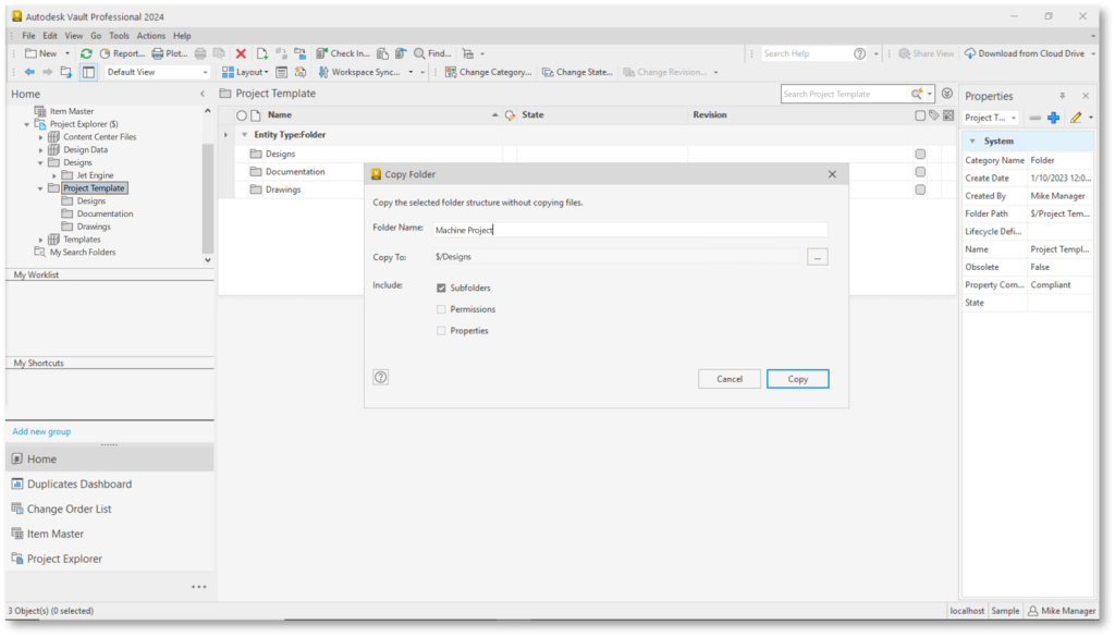
Contact Us

If you would to discuss Autodesk software, please contact us by calling on 1800 490 514, by filling out the form or clicking the live chat in the bottom right-hand corner.

Contact Us Moving at the Speed of Business

VIEW MORE

Autodesk Promos

Autodesk 22 A Logo Large Moving at the Speed of Business

HUGE SAVINGS ON AUTODESK SOFTWARE!

Autodesk Deal Days Sale Starts 11/07/2022 and Ends on 13/07/2022

Days
Hours
Minutes
Seconds

Over 20% off Selected Autodesk Software

$2,499 - 1Yr

$7,299 - 3Yr

$589 - 1Yr

$1,689 - 3Yr

$2,099 - 1Yr

$5,989 - 3Yr

$999 - 1Yr

$2,999 - 3Yr

$2,099 - 1Yr

$5,989 - 3Yr

$565 - 1Yr

$1,649 - 3Yr

Over 20% off AutoCAD

$2,499 - 1Yr

$7,299 - 3Yr

Over 20% off AutoCAD

$2,499 - 1Yr

$7,299 - 3Yr

Up to $960 off Autodesk Inventor Pro

Up to $1,400 off Industry Collections

Up to $1,100 off Autodesk Revit

Up to 20% off Autodesk AutoCAD LT

Up to 20% off Autodesk Revit LT

20% off Training Sessions

Premium Technical Support

Get Notified - Contact Us

Contact Form Demo

VIEW MORE

Autodesk Software, Autodesk Training Courses and Bluebeam Shop

Autodesk Software, Autodesk Traiing, Bluebeam pdf software, AutoCAD, Inventor Professional, Autodesk Subscriptions, aec collection, pdm collection, Architecture Engineering and Construction Collection, Product Design & Manufacturing Collection, Civil 3D, Advance Steel

Shop Autodesk Products

Search
Sort by
$ -
Category
Vendor
Industry
  • Architecture(0)
  • Architecture, Structural, Electrical, Mechanical, Piping, Construction, Infrastructure(0)
  • Architecture, Structural, Mechanical, Electrical, Piping, Linear FEA(0)
  • Automotive(0)
  • Construction(0)
  • Electrical(0)
  • General(0)
  • General, Architecture, Manufacturing, Oil & Gas(0)
  • Infrastructure(0)
  • Manufacturing(0)
  • Manufacturing, Product Design(0)
  • Mechanical(0)
  • Media & Entertainment(0)
  • Media and Entertainment(0)
  • MEP(0)
  • Product Design(0)
  • Structural(0)
  • VFX(0)
Features
Included Software

    keywords: Autodesk software, Autodesk training courses, Bluebeam, Bluebeam software, AutoCAD, Inventor Professional, Revit, Architecture Engineering and Construction Collection, aec collection, pdm collection, Product Design & Manufacturing Collection, Civil 3D, Advance Steel, navisworks, Autodesk Subscription, Autodesk licence, Autodesk license, AutoCAD Subscription cost, AutoCAD licence cost, Revit licence, Revit license, Revit Subscription cost, Revit licence cost, Inventor Professional licence, Inventor Professional license, Inventor Professional Subscription cost, Inventor Professional licence cost


    VIEW MORE