1800 490 514 [email protected]

Connected Design with the Autodesk Architecture Engineering and Construction Collection
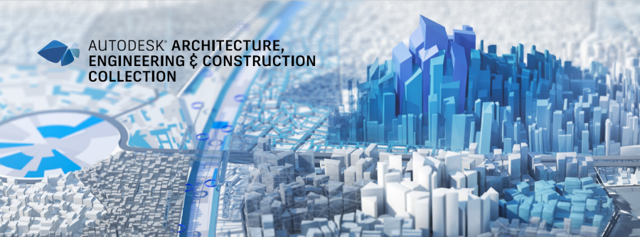
The Autodesk Architecture, Engineering and Construction Collection streamlines design, analysis, and visualization for architecture, engineering, construction, infrastructure, and manufacturing industries. The suite of software programs improves efficiency, reduces errors and rework, and increases cost-effectiveness.
Design Consulting Architecture Engineering and Construction Collection logo Moving at the Speed of Business

Connected Design with the Autodesk Architecture Engineering and Construction Collection

In today’s fast-paced world, the construction industry is continuously evolving with new technology advancements. As technology advances, it becomes essential to have an efficient and connected design process that incorporates design, analysis, and visualization. The Autodesk Architecture, Engineering and Construction Collection is a comprehensive suite of software programs that facilitate this process. This blog post will discuss how the Autodesk Architecture, Engineering and Construction Collection can benefit various industries by connecting design, analysis, and visualization.

Connected Design Workflow: How Software Programs Work Together

The Autodesk Architecture, Engineering and Construction Collection consists of multiple software programs that allow for a connected design workflow. The software programs in the collection work together seamlessly, allowing for efficient design, analysis, and visualization. The collection includes software programs such as AutoCAD, Revit, Navisworks, and more. Each software program is designed to perform a specific task, and when used together, they create a comprehensive design workflow.

Designing with Precision: AutoCAD and Revit in the AEC Collection

The first step in any construction project is design. The Autodesk Architecture, Engineering and Construction Collection includes various software programs that aid in the design process. AutoCAD is a widely used software program that allows for 2D and 3D drafting. AutoCAD is used to create detailed drawings, and it is compatible with other software programs in the collection. Revit is another software program that is used in the design process. Revit allows for BIM (Building Information Modelling), which helps in creating a detailed 3D model of the building. By using Revit, the design process becomes more efficient, as the software program allows for collaboration between various stakeholders.

Revit and Civil 3D: Enhancing Infrastructure and Construction Projects with 3D Modeling and Efficient Design Collaboration

Revit and Civil 3D are commonly used in the AEC industry for infrastructure and construction projects. Revit creates 3D models of buildings, while Civil 3D designs infrastructure projects. Used together, they complement each other and improve the design process by identifying potential design issues in 3D models. Changes made in one software program are automatically updated in the other. This streamlines the design process and helps identify issues early in the design phase.

Ready to Get Connected?

Save up to 20% on Autodesk Software and Services

How Revit and Advance Steel Work Together to Streamline Steel Design and Fabrication

Revit and Advance Steel are two software programs that can be used together in the architecture, engineering, and construction (AEC) industry. Revit is a building information modeling (BIM) software that is used to create 3D models of buildings, while Advance Steel is a 3D modeling software that is used to design steel structures.

When used together, Revit and Advance Steel can improve the efficiency and accuracy of the design process. For example, an engineer can create a 3D model of a building in Revit and then export it to Advance Steel to design the steel structure. The engineer can then import the steel structure design back into Revit to ensure that it is compatible with the rest of the building design.

In addition, when changes are made in one software program, they are automatically updated in the other software program. This means that any changes made to the steel structure design in Advance Steel will be automatically reflected in the building design in Revit, and vice versa.

Using Revit and Advance Steel together can also help identify potential design issues early in the design phase. The 3D models created in Revit and Advance Steel can be used to identify clashes or conflicts that may have been missed in 2D design drawings. This can help save time and reduce the risk of errors and rework later in the project.

In conclusion, Revit and Advance Steel are powerful software programs that can be used together to improve the efficiency and accuracy of the design process in the AEC industry. The ability to export and import design elements between the two software programs and ensure that changes are automatically updated can streamline the design process and help identify potential issues early in the design phase.

Efficient Analysis with Navisworks and Autodesk Robot Structural Analysis Professional

The Autodesk Architecture, Engineering and Construction Collection includes software programs that aid in the analysis process. Navisworks is a software program that allows for coordination and simulation of construction projects. Navisworks helps in identifying clashes, reducing errors and rework, and creating more efficient designs. Additionally, Autodesk Robot Structural Analysis Professional is used to perform structural analysis of buildings. The software program helps in identifying structural deficiencies and optimizes the design process.

Bringing GIS Mapping and Connected Design Together: A Comprehensive Approach with Autodesk's AEC Collection

In today’s world, design and construction projects require a more comprehensive approach than ever before. With the Architecture Engineering and Construction (AEC) Collection from Autodesk, architects, engineers, and construction professionals have access to a suite of powerful tools that can help them collaborate and work more efficiently. One of the most valuable features of the AEC Collection is its ability to integrate with Geographic Information Systems (GIS) mapping, providing a more accurate and detailed view of project sites and landscapes.

AutoCAD Map 3D is a powerful software tool for GIS mapping, which allows users to access, manage and analyse spatial data. With AutoCAD Map 3D, users can easily import and export data from various sources, such as aerial imagery, satellite imagery, and other GIS data. This software also provides a wide range of tools for data analysis, visualization and editing, making it an essential tool for GIS professionals. Some of the key features of AutoCAD Map 3D include 3D modelling and visualisation, data query and analysis, and advanced geospatial analysis tools. By leveraging these features, users can create accurate and comprehensive maps and spatial data sets for a wide range of applications.

GIS mapping is a critical component of many construction projects, particularly those that involve large-scale developments or infrastructure. By overlaying geographic data such as topography, hydrology, and geology onto a digital map, project teams can better understand the context of their projects and make more informed decisions. The AEC Collection’s integration with GIS mapping tools allows architects, engineers, and construction professionals to access this data within their design software, creating a more seamless and connected workflow.

With the AEC Collection, design professionals can also collaborate with each other in real-time using tools such as Navisworks and Docs. Navisworks allows teams to integrate and coordinate models from multiple disciplines, while Docs enables document management and sharing across teams. By using these tools in conjunction with GIS mapping, project teams can ensure that all stakeholders have access to the most up-to-date information, reducing errors and improving overall project efficiency.

Enhancing Oil and Gas Plant Design with the AEC Collection and Plant 3D

The Architecture Engineering and Construction (AEC) Collection is a powerful suite of software programs designed to facilitate connected design for the architecture industry. One of the key software programs in this collection is Plant 3D, which is specifically designed for oil and gas plant design.

Plant 3D is a comprehensive software program that enables users to design, model, and analyze piping and instrumentation diagrams (P&ID) for oil and gas plants. With its intuitive interface and advanced tools, Plant 3D allows users to create accurate and detailed 3D models of plant layouts, equipment, and piping systems.

One of the key advantages of using the AEC Collection and Plant 3D for oil and gas plant design is the ability to collaborate with other disciplines in the industry, such as civil engineering and structural design. By working together in a connected design environment, designers and engineers can ensure that all aspects of the plant design are integrated seamlessly, from the initial concept through to construction and operation.

In addition, the AEC Collection and Plant 3D offer a range of powerful tools for data management and analysis, enabling users to track and monitor plant performance, optimize plant layouts, and identify potential safety hazards or operational issues.

Some of the key features of Plant 3D include:

  • Intelligent P&ID design and management tools
  • Comprehensive 3D modeling capabilities
  • Advanced piping and instrumentation analysis tools
  • Integration with other AEC Collection software programs, such as Navisworks and Docs

By leveraging these features, designers and engineers in the oil and gas industry can streamline their design processes, improve collaboration, and ensure that their plant designs are optimized for safety, efficiency, and performance.

Enhancing Visualisation with 3DS Max and InfraWorks

Visualisation is an essential part of any construction project. The Autodesk Architecture, Engineering and Construction Collection includes software programs that aid in the visualization process. 3DS Max is a software program that allows for rendering and animation of 3D models. 3DS Max helps in creating realistic visuals, which help in selling designs to clients. Autodesk InfraWorks is another software program that helps in creating visualizations of infrastructure projects. InfraWorks allows for collaboration between various stakeholders, and it helps in creating a more efficient design process.

Streamlining AEC Projects with Autodesk Docs

Autodesk Docs is a powerful document management tool that can help streamline AEC projects when used in conjunction with the Architecture Engineering and Construction Collection (AEC Collection) software. The AEC Collection includes several software programs that are essential for building design and construction, including Revit, Civil 3D, and Advance Steel.

By using Autodesk Docs to manage project documents, stakeholders can easily access and collaborate on project files from anywhere, at any time. This can improve project efficiency and communication, as all team members can stay up-to-date on project progress and changes.

Moreover, the AEC Collection software can be seamlessly integrated with Autodesk Docs, allowing users to store and manage their project files directly within Autodesk Docs. This integration makes it easier for teams to collaborate on project files and ensures that all project documentation is stored in one place, reducing the risk of lost or missing files.

For example, Revit models can be directly linked to Autodesk Docs, allowing team members to access and collaborate on the most up-to-date model at all times. Civil 3D designs can also be stored in Autodesk Docs, making it easy to share and collaborate on complex civil engineering projects.

Overall, by using Autodesk Docs in conjunction with the AEC Collection software, AEC professionals can streamline their project workflows, improve collaboration and communication, and ensure that project documentation is secure and easily accessible.

AEC Collection in Various Industries: Architecture, Engineering, Construction, Infrastructure, and Manufacturing

The Autodesk Architecture, Engineering and Construction Collection is beneficial to various industries. Here are a few examples:

Architecture: The Autodesk Architecture, Engineering and Construction Collection is used by architects to design and visualise buildings. The software programmes in the collection allow for efficient design, analysis, and visualisation.

Engineering: Engineers use the Autodesk Architecture, Engineering and Construction Collection to perform structural analysis and design. The software programmes in the collection help in identifying structural deficiencies, optimising designs, and creating efficient designs.

Construction: The Autodesk Architecture, Engineering and Construction Collection is used in the construction industry to coordinate and simulate construction projects. The software programmes in the collection help in identifying clashes, reducing errors and rework, and creating more efficient designs.

Infrastructure: The Autodesk Architecture, Engineering and Construction Collection is used in the infrastructure industry to design and visualise infrastructure projects. The software programmes in the collection, such as InfraWorks, help in creating visualisations of infrastructure projects. InfraWorks allows for collaboration between various stakeholders, including engineers, designers, and contractors. By using the Autodesk Architecture, Engineering and Construction Collection, infrastructure projects can be completed more efficiently and cost-effectively.

Manufacturing: The Autodesk Architecture, Engineering and Construction Collection is also used in the manufacturing industry. The collection includes software programmes that aid in the design of manufacturing equipment and machinery. Autodesk Inventor, for example, is used to design and test products before they are manufactured, reducing errors and costs.

Architecture Engineering and Construction Collection Connected Design Matrix

SoftwareDescriptionFile TypeCommandImport/ExportLink
AutoCAD2D and 3D computer-aided design software used for creating blueprints, schematics, and modelsDWG, DXF, DWFDRAWING, MODEL, VIEW, PLOTImport: DWG, DXF, DWF, PDF, STEP, SAT, IGES, STLExport: DWG, DXF, DWF, PDF, STL, OBJ, FBX
RevitBuilding information modeling (BIM) software used for creating detailed 3D models of buildings and structuresRVT, RFA, RTEOPEN, VIEW, EXPORT, PRINTImport: DWG, DXF, IFC, SAT, SKP, 3DM, STL, OBJ, FBXExport: DWG, DXF, DWF, PDF, IFC, SAT, SKP, 3DM, STL, OBJ, FBX
Civil 3DCivil engineering design and documentation software used for designing, analyzing, and documenting civil engineering projectsDWGCIVIL3D, C3DImport: DWG, LandXML, RevitExport: DWG, LandXML, Revit
InfraWorksInfrastructure design and engineering software used for creating 3D models of infrastructure projectsIAMOPEN, MODEL, VIEW, EXPORT, PUBLISHImport: DWG, DGN, GIS, SHP, KML, FBXExport: DWG, DGN, FBX, COLLADA, OBJ, IFC, KMZ
3ds Max3D modeling, animation, and rendering software used for creating visualizations of buildings and environmentsMAXOPEN, MODEL, RENDERImport: DWG, FBX, DAE, OBJ, 3DS, STLExport: DWG, FBX, DAE, OBJ, 3DS, STL
NavisworksProject review software used for 3D coordination, model analysis, and clash detectionNWD, NWFOPEN, APPEND, EXPORT, PUBLISHImport: DWG, DWF, DGN, IFC, SKP, FBX, 3DS, OBJExport: DWF, DWFx, NWC, NWF, FBX, 3DS, OBJ
Advance SteelSteel detailing software used for creating structural steel models and fabrication drawingsDWG, DSTVOPEN, MODEL, EXPORTImport: DWG, CIS/2, SDNF, IFC, STEP, SAT, SKPExport: DWG, DSTV, CIS/2, SDNF, IFC, STEP, SAT, SKP
Robot Structural Analysis ProfessionalStructural analysis software used for simulating and analyzing building structuresRST, RSA  

AEC Collection: A Valuable Tool for Cost-Effective Design Processes.

In conclusion, the Autodesk Architecture, Engineering and Construction Collection is a comprehensive suite of software programs that facilitates a connected design workflow. The software programs in the collection work together seamlessly, allowing for efficient design, analysis, and visualization. By using the Autodesk Architecture, Engineering and Construction Collection, various industries can benefit from a more efficient and cost-effective design process. The collection is beneficial to architects, engineers, construction professionals, infrastructure designers, and manufacturers. The collection is continuously evolving to meet the needs of these industries, and it remains a valuable tool in the construction industry.

Ready to get your Design Connected?

Discover how Autodesk Architecture Engineering and Construction Collection can streamline your workflow, increase productivity, and optimise your design process. 

Get up to 20% Off Software or Services!

Contact us to find out how much money you can save on software, training or other services. Fill out the form below, by live chat, phone or email.

P: 1800 490 514 |  E: [email protected]
Connected Design

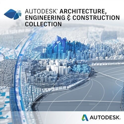
The Autodesk Architecture, Engineering and Construction Collection streamlines design, analysis, and visualization for architecture, engineering, construction, infrastructure, and manufacturing industries. The suite of software programs improves efficiency, reduces errors and rework, and increases cost-effectiveness.

Connected Design with Architecture Engineering and Construction Collection

Click a link below to learn more about Connected Design using the Autodesk Product Design & Manufacturing Collection 

VIEW MORE

Connected Structural Design with Autodesk Product Design & Manufacturing Collection

Connected Structural Design Moving at the Speed of Business
Design Consulting Product Design Manufacturing Collection Moving at the Speed of Business

Connected Structural Design with Autodesk Product Design & Manufacturing Collection

Transforming Structural Design with Autodesk Product Design & Manufacturing Collection

The Autodesk Product Design and Manufacturing Industry Collection is a comprehensive set of software tools for designing and manufacturing products across various industries. This collection includes software for 3D design, engineering, and production, and it’s ideal for product designers and manufacturers. In this blog post, we will explore the connected structural design tools in Autodesk Inventor and how they can be used to design and analyse structures. We will also discuss how the structural designs from Inventor can be used in Plant 3D to design production plants, oil and gas projects, and how to export dwg or adsk file formats to AutoCAD.

Structural Design and Analysis Tools in Autodesk Inventor

Autodesk Inventor offers a range of structural design and analysis tools that enable users to create complex structures with ease. The software comes equipped with frame generator, sheet metal, and assembly modeling environment to facilitate the design of structural elements. These tools are ideal for designers and engineers who need to create robust and reliable structures.

Exporting dwg or adsk File Formats to AutoCAD

Autodesk Inventor offers the ability to export designs in dwg or adsk file formats to AutoCAD. This feature enables users to work with the designs in AutoCAD, which is useful for designers who need to create 2D drawings or for those who prefer working in AutoCAD. The process of exporting designs is straightforward and requires only a few clicks.

Structural Design in Plant 3D

Plant 3D is a specialized toolset of AutoCAD that allows users to design and analyse production plants, oil and gas projects, and other industrial structures. Users can utilise structural designs created in Inventor in Plant 3D to design various elements such as pipe supports, equipment, and structural steel. This feature enables designers to create a comprehensive 3D model that includes all the structural and mechanical elements of a plant.

Frame Generator

Frame Generator is a powerful tool in Autodesk Inventor that enables users to design and create structural frames with ease. This tool allows users to create complex frame structures using pre-defined structural shapes or custom shapes. The tool also provides the ability to create structural members with different cross-sections and apply various constraints to optimize the frame’s strength and stability.

Frame Analysis

Frame Analysis is a feature in Autodesk Inventor that allows users to analyse and optimize frame structures. This feature provides a comprehensive set of tools for analysing frames, including calculating the frame’s natural frequencies, calculating the stresses and displacements, and evaluating the frame’s stability. The tool also provides the ability to modify the frame’s design and re-run the analysis to optimise the frame’s performance.

Simulation

Autodesk Inventor offers simulation tools that enable users to simulate various types of mechanical and structural behavior, including structural analysis, motion analysis, and dynamic simulation. These tools allow users to evaluate the structural and mechanical performance of their designs, identify potential issues, and optimize their designs for better performance.

Ready to Get Connected?

Save up to 20% on Autodesk Software and Services

Nastran Structural Simulation Analysis

Nastran Structural Simulation Analysis is a comprehensive simulation tool in Autodesk Inventor that allows users to simulate and analyse complex mechanical and structural behaviour. This tool provides advanced simulation capabilities for analysing stress, deformation, vibration, and other mechanical behaviours. The tool also provides the ability to perform finite element analysis (FEA) to optimize designs for better performance.

Structural Design Workflow

The workflow from designing a structural design in Inventor to performing a frame analysis and Nastran structural analysis study involves several steps, which are as follows:

Step 1: Designing the Structural Design in Inventor

The first step is to create the structural design in Autodesk Inventor using tools such as Frame Generator, Sheet Metal, or Assembly Modelling Environment. The design can include various elements, such as beams, columns, braces, and trusses.

Step 2: Preparing the Model for Analysis

Once the structural design is created, the next step is to prepare the model for analysis. This involves assigning material properties, loads, and boundary conditions to the model. Material properties include properties such as modulus of elasticity, Poisson’s ratio, and density, while loads and boundary conditions can include forces, moments, supports, and constraints.

Step 3: Performing a Frame Analysis

The next step is to perform a frame analysis to evaluate the structural behaviour of the design. In Autodesk Inventor, Frame Analysis can be performed using the Frame Analysis Environment. This environment allows users to perform various types of analysis, including static, modal, and buckling analysis. Frame Analysis can be used to calculate natural frequencies, stresses, and deformations of the structure.

Step 4: Performing a Nastran Structural Analysis Study

If more advanced analysis is required, a Nastran Structural Analysis Study can be performed. Nastran is a finite element analysis software that is integrated into Autodesk Inventor. This tool provides advanced simulation capabilities for analysing stress, deformation, and other mechanical behaviours. It can also be used to perform more complex analyses, such as dynamic and thermal analysis.

Step 5: Optimizing the Design

Once the analysis is complete, the next step is to optimize the design based on the results of the analysis. This can involve modifying the structural design or adjusting the loads and boundary conditions to improve the performance of the design.

Step 6: Iterating the Process

Finally, the design process is iterated, with the model being adjusted and re-analysed until an optimal design is achieved. This can involve going back to Step 2 and re-defining the loads and boundary conditions, or adjusting the design in Inventor and re-analysing in the Frame Analysis or Nastran Structural Analysis Study environment.

In summary, the workflow from designing a structural design in Inventor to performing a Frame Analysis and Nastran Structural Analysis Study involves several steps, including preparing the model for analysis, performing the analysis, optimizing the design, and iterating the process until an optimal design is achieved. These tools in Inventor allow for the creation of complex structures and ensure their mechanical behaviour is analysed and optimized for performance.

Ready to get your Structural Design Connected?

Discover how Autodesk Product Design & Manufacturing Collection can streamline your workflow, increase productivity, and optimise your design process. 

Get up to 20% Off Software or Services!

Contact us to find out how much money you can save on software, training or other services. Fill out the form below, by live chat, phone or email.

P: 1800 490 514 |  E: [email protected]

Connected Design

Connected Structural Design Moving at the Speed of Business

Connected Design with Product Design & Manufacturing Collection

Click a link below to learn more about Connected Design using the Autodesk Product Design & Manufacturing Collection 

VIEW MORE

Connected Mechanical Design with Autodesk Product Design & Manufacturing Collection

Connected Mechanical Design 2 Moving at the Speed of Business
Design Consulting Product Design Manufacturing Collection Moving at the Speed of Business

Connected Mechanical Design with Autodesk Product Design & Manufacturing Collection

Streamlining Mechanical Design with Product Design & Manufacturing Collection: A Guide to Connecting Autodesk Inventor, Fusion 360, AutoCAD, and AutoCAD Mechanical

Mechanical design is an intricate process that requires the use of multiple software tools. Each software tool has its unique features, which are essential for creating a functional design. The Product Design & Manufacturing Collection from Autodesk brings together all the necessary tools for mechanical design. This collection includes Autodesk Inventor, Fusion 360, AutoCAD, and AutoCAD Mechanical. By using these tools together, mechanical design becomes more streamlined and efficient. In this guide, we will explore the benefits of using these tools in conjunction with each other and provide a step-by-step process on how to connect them for maximum efficiency.

Overview of Product Design & Manufacturing Collection

The Product Design & Manufacturing Collection from Autodesk is a comprehensive collection of software tools that are designed to streamline the product design process. The collection includes Autodesk Inventor, Fusion 360, AutoCAD, and AutoCAD Mechanical. These tools work together seamlessly, allowing engineers and designers to collaborate on projects and share data across platforms. By using these tools together, teams can reduce errors, improve accuracy, and speed up the design process.

The Benefits of Using Autodesk Inventor, Fusion 360, AutoCAD, and AutoCAD Mechanical Together

The benefits of using Autodesk Inventor, Fusion 360, AutoCAD, and AutoCAD Mechanical together are numerous. First, the tools provide a comprehensive set of features that cover all aspects of mechanical design, from 3D modeling to simulation to manufacturing. Second, the tools are designed to work together seamlessly, allowing teams to collaborate on projects and share data across platforms. Third, the tools are constantly updated and improved, ensuring that users always have access to the latest features and functionality.

Connecting Autodesk Inventor, Fusion 360, AutoCAD, and AutoCAD Mechanical

To connect Autodesk Inventor, Fusion 360, AutoCAD, and AutoCAD Mechanical, follow these steps:

Install all the software tools from the Product Design & Manufacturing Collection on your computer.

Open Autodesk Inventor and create a new part or assembly.

From the menu bar, select “Manage” and then select “Import/Export.”

From the dropdown menu, select the file format you wish to use (e.g., DWG, DXF, IGES).

Select the file you wish to import and click “Open.”

The file will be imported into Autodesk Inventor, and you can start working on it.

Using Autodesk Inventor, Fusion 360, AutoCAD, and AutoCAD Mechanical for Mechanical Design

Autodesk Inventor is a powerful 3D CAD software that is used for mechanical design. It allows designers to create 3D models of parts and assemblies, perform simulations, and generate documentation. Fusion 360 is a cloud-based CAD/CAM software that allows designers and engineers to collaborate on projects in real-time. AutoCAD is a 2D CAD software that is used for creating detailed drawings, and AutoCAD Mechanical is a 3D CAD software that is used for mechanical design.

Ready to Get Connected?

Save up to 20% on Autodesk Software and Services

Unlocking the Power of AnyCAD: Combining Autodesk Inventor, Fusion 360, and AutoCAD Mechanical for Seamless Mechanical Design

AnyCAD in Autodesk Product Design & Manufacturing Collection lets you transfer 3D models between different software platforms effortlessly, making collaboration on complex projects easier. AnyCAD enables you to link Autodesk Inventor, Fusion 360, and AutoCAD Mechanical to create an integrated mechanical and electrical design with automatic updates. The 2D detailing in AutoCAD Mechanical benefits from AnyCAD’s ability to import the Inventor model, maintaining a single source of truth for design data and reducing the risk of errors.

Front page Moving at the Speed of Business

AnyCAD and DWG Files

Autodesk Inventor and AutoCAD are powerful design tools for 3D and 2D design, respectively. With AnyCAD, users can import AutoCAD DWG files into Inventor and work with both 2D and 3D geometry. AnyCAD eliminates the need for manual conversions and allows for faster and more accurate design changes. It also enables users to work with annotations and other design details in both environments, improving collaboration and communication between stakeholders. Overall, AnyCAD streamlines the design process, making it more efficient and accurate.

inventor 2021 revit to inventor anycad 11 1024x1024 1 Moving at the Speed of Business

Combining all Designs from Fusion 360 and AutoCAD Mechanical into Autodesk Inventor

The Product Design & Manufacturing Collection from Autodesk offers a suite of powerful tools for designing and manufacturing products. One of the major benefits of this collection is the ability to seamlessly integrate designs from different software platforms, such as Autodesk Inventor, Fusion 360, and AutoCAD Mechanical. In this post, we’ll explore how to combine all designs from Fusion 360 and AutoCAD Mechanical into Autodesk Inventor.

Importing Fusion 360 designs

To import a Fusion 360 design into Inventor using Anycad, you first need to export the design as a STEP file from Fusion 360. In Fusion 360, select the design you want to export, go to the File menu, and select Export. Choose the STEP file format and save the file.

Next, open an Inventor assembly and go to the Anycad tab. Click on the Import command and select the exported STEP file. The Fusion 360 design will now be imported into the Inventor assembly, where you can combine it with other designs.

Importing AutoCAD Mechanical designs

To import an AutoCAD Mechanical design into Inventor using Anycad, you need to export the design as a DWG file from AutoCAD Mechanical. In AutoCAD Mechanical, select the design you want to export, go to the File menu, and select Save As. Choose the DWG file format and save the file.

Next, open an Inventor assembly and go to the Anycad tab. Click on the Import command and select the exported DWG file. The AutoCAD Mechanical design will now be imported into the Inventor assembly, where you can combine it with other designs.

Combining all designs in Inventor

Once you’ve imported the designs from Fusion 360 and AutoCAD Mechanical into Inventor, you can start combining them. You can use the assembly tools in Inventor to mate and constrain the different components, creating a complete 3D model. You can also use the drawing tools in Inventor to create 2D drawings and detailing.

Combining all Designs into AutoCAD Mechanical

When using the Product Design & Manufacturing Collection, it’s possible to combine the strengths of different software programs to create a more comprehensive mechanical design workflow. One example of this is using Autodesk Inventor to create a 3D mechanical model, which could have a Fusion 360 model linked into it.

Once the 3D model is complete, it can be imported into AutoCAD Mechanical to further refine the design and create detailed 2D drawings. AutoCAD Mechanical offers a range of powerful tools for creating mechanical drawings, including the ability to create and edit mechanical symbols, automate common tasks, and easily generate bills of materials.

To import the Inventor model into AutoCAD Mechanical, simply use the “Insert” command to bring the 3D model into the 2D workspace. Once the model is in place, you can use AutoCAD Mechanical’s powerful annotation tools to add dimensions, notes, and other details to your drawings.

It’s worth noting that AutoCAD Mechanical also has a range of built-in tools for working with Inventor files directly, including the ability to import Inventor assemblies and parts directly into the software. This can be a great way to leverage existing Inventor designs and incorporate them into your AutoCAD Mechanical workflows.

Overall, the combination of Inventor, Fusion 360, and AutoCAD Mechanical offers a powerful suite of tools for mechanical design and detailing. By leveraging the strengths of each software program, designers can create comprehensive mechanical designs and detailed 2D drawings with greater efficiency and accuracy.

Ready to get your Mechanical Design Connected?

Discover how Autodesk Product Design & Manufacturing Collection can streamline your workflow, increase productivity, and optimise your design process. 

Get up to 20% Off Software or Services!

Contact us to find out how much money you can save on software, training or other services. Fill out the form below, by live chat, phone or email.

P: 1800 490 514 |  E: [email protected]

Connected Design

Connected Mechanical Design 2 Moving at the Speed of Business

Connected Design with Product Design & Manufacturing Collection

Click a link below to learn more about Connected Design using the Autodesk Product Design & Manufacturing Collection 

VIEW MORE

Top Ten IMAGINiT Clarity Tasks

IMAGINiT Clarity thumb 1 Moving at the Speed of Business

TOP TEN IMAGINIT CLARITY TASKS

IMAGINiT Clarity is a powerful automation system for Autodesk Revit where it automatically processes manual tasks in Revit, IT administrative tasks, data extraction and transferring files from one location to another plus more.

Below is the top 10 tasks in IMAGINiT Clarity.

10. Index Model Families

IMAGINiT Clarity can automate the indexing of Revit families so you can understand the quality and usage of Revit families within your projects.

9. Project Backups

Automatically back up Revit projects to multiple file formats, platforms and locations and take regular snapshots with custom filenaming.

8. DWG Tasks

Automatically generate DWG files from the Revit model.

7. Publish to BIM 360

Automatically publish Revit models and other files such as PDF, DWG, IFC and many other formats to BIM 360. IMAGINiT Clarity can download the latest model from BIM 360 automatically generate PDF, DWG and other file formats and upload them automatically to BIM 360.

6. Performance Advisor

Get alerts on impending project issues including inflated file size and unresolved warnings

5. Navisworks

Create or update Navisworks models from the Revit model.

4. Revit DBE Export

Extract Revit model data into a database

3. Model Metrics

IMAGINiT Clarity can graph over 50 metrics and custom metrics from Dynamo scripts, Revit macros and the Revit API

2. Publish Revit Model

Publish, clean and share Revit models with external stakeholders

1. PDF Tasks

Prints PDF sets and batch generation of PDF Books

Contact Us

If you would learn more about IMAGINiT Clarity, please contact us by calling on 1800 490 514, by filling out the form or clicking the live chat in the bottom right-hand corner.

VIEW MORE

Moving from Pen and Pad to Pen and CAD

Digitising Concept Sketch Designs Change… hard to do but necessary when the world around you changes and it’s challenging to move from what you know to something better and having to re-learn, but it doesn’t have to be. Designs usually start with a pen and pad and a lot of erasing and design changes and variations, which is why…

VIEW MORE