1800 490 514 [email protected]

Connected Structural Design with the Autodesk Architecture Engineering and Construction Collection
Learn how the Autodesk AEC Collection connects Advance Steel, Revit and other programs for structural design, analysis and fabrication
Design Consulting Architecture Engineering and Construction Collection logo Moving at the Speed of Business

Connected Structural Design with the Autodesk Architecture Engineering and Construction Collection

The construction industry has seen a significant transformation in recent years with the adoption of new technologies and software. Structural engineering is no exception, as it plays a crucial role in the success of any construction project. Autodesk Architecture, Engineering, and Construction (AEC) Industry Collection is a suite of powerful software tools that enable structural engineers and fabricators to streamline their workflows and improve collaboration.

In this blog post, we will explore how Advance Steel, a software tool within the AEC Industry Collection, works with other applications such as Revit, Autodesk Docs, Robot Structural Analysis, Navisworks, and more to create a connected design process. We will also discuss the benefits of this approach for structural engineers and fabricators on construction projects.

How Does Advance Steel Work With Other Applications in the Collection?

With the AEC Industry Collection, structural engineers can create detailed designs, collaborate with architects and other stakeholders, and analyse their designs for efficiency and safety. Fabricators can use the software to create shop drawings and CNC files, and contractors can use it to manage construction projects and ensure that they stay on schedule and on budget.

Advance Steel is a software tool within the AEC Industry Collection that provides 3D modeling and detailing for steel structures. It is designed to streamline the design and fabrication process for steel structures, making it easier for engineers and fabricators to collaborate and ensure accuracy.

Advance Steel can be used to create detailed steel models in 3D, including connections, plates, and bolts. It also provides tools for creating drawings, bills of materials, and NC files for fabrication. With Advance Steel, engineers and fabricators can ensure that their designs are accurate and meet industry standards.

How Advance Steel works with other applications in the AEC Industry Collection

One of the key benefits of the AEC Industry Collection is that it provides a connected design process. This means that engineers and fabricators can use multiple software tools in the collection to streamline their workflows and ensure accuracy.

Here are some of the ways that Advance Steel works with other applications in the AEC Industry Collection:

  1. Revit: Advance Steel can be used with Revit to create detailed steel models that include all of the necessary information for fabrication. Revit can also be used to create detailed architectural and MEP models, which can be linked to the steel model in Advance Steel for coordination.

  2. Autodesk Docs: Autodesk Docs is a cloud-based document management platform that can be used to store and share project information. With Autodesk Docs, engineers and fabricators can collaborate on design files, RFIs, submittals, and more.

  3. Robot Structural Analysis: Robot Structural Analysis is a software tool that can be used to analyse steel structures for safety and efficiency. With Robot Structural Analysis, engineers can perform finite element analysis (FEA) on their steel models to ensure that they meet industry standards.

  4. Navisworks: Navisworks is a software tool that can be used for project coordination and clash detection. With Navisworks, engineers can import steel models from Advance Steel and other software tools to check for clashes and ensure.

  5. Other Applications: The AEC Industry Collection includes a wide range of other software tools that can be used in conjunction with Advance Steel. For example, Fabrication CADmep can be used to create detailed ductwork and piping models that can be linked to the steel model in Advance Steel for coordination.


Benefits of Connected Design for Structural Engineers and Fabricators

The connected design process enabled by the AEC Industry Collection provides several benefits for structural engineers and fabricators. Here are some of the key advantages:

  1. Improved Collaboration: By using multiple software tools in the AEC Industry Collection, engineers and fabricators can collaborate more effectively. They can share design files, coordinate different aspects of the project, and ensure that everyone is working from the same information.

  2. Streamlined Workflows: The connected design process also streamlines workflows by reducing the need for manual data entry and rework. Engineers and fabricators can move seamlessly between different software tools, and the data is automatically synchronised.

  3. Increased Accuracy: By using software tools like Advance Steel, engineers and fabricators can ensure that their designs are accurate and meet industry standards. They can also perform analysis and simulations to ensure that the structure is safe and efficient.

  4. Faster Time-to-Market: The connected design process enables faster time-to-market by reducing the time needed for design and fabrication. This can help construction companies stay on schedule and avoid delays.

  5. Cost Savings: Finally, the connected design process can also lead to cost savings by reducing the need for rework and minimising errors. This can help construction companies stay on budget and avoid costly mistakes.

Ready to Get Connected?

Save up to 20% on Autodesk Software and Services

How Dynamo is Revolutionising Structural Design with Advance Steel and Revit

Dynamo is a visual programming tool that is transforming the way structural engineers and designers work. When combined with software tools like Advance Steel and Revit, it offers several benefits that can help streamline workflows and increase efficiency. In this article, we’ll explore the benefits of using Dynamo with Advance Steel and Revit for structural design.

  1. Automating Repetitive Tasks

One of the main benefits of using Dynamo with Advance Steel and Revit is the ability to automate repetitive tasks. For example, Dynamo can be used to automatically create connections between steel elements in Advance Steel based on predefined rules. This can save time and reduce errors, allowing engineers and designers to focus on more complex tasks.

  1. Enhanced Collaboration

Dynamo also improves collaboration between different teams involved in the structural design process. By using a visual programming language, designers and engineers can easily share scripts and workflows with other team members, regardless of their level of technical expertise. This helps to improve communication and ensures that everyone is working from the same information.

  1. Increased Accuracy and Quality

Using Dynamo with Advance Steel and Revit can help improve the accuracy and quality of structural designs. For example, Dynamo can be used to automatically calculate loads and reactions for a structure, or to optimize the size and shape of steel members. This can lead to more efficient and cost-effective designs, as well as better structural performance.

  1. Streamlined Workflows

Dynamo helps to streamline workflows by eliminating the need for manual data entry and reducing the potential for errors. By automating repetitive tasks and using a visual programming language, engineers and designers can move seamlessly between different software tools, saving time and reducing the potential for delays and mistakes.

  1. Improved Visualization

Finally, using Dynamo with Advance Steel and Revit can improve visualisation of the design. With Dynamo, engineers and designers can create complex geometry and parametric models, allowing for greater flexibility and better visualisation of the structure. This can help identify potential issues and make design decisions more effectively.

FeaturesAutoCADAdvance SteelRevit
2D DraftingComprehensive set of 2D drafting tools, including line, circle, polyline, arc, and text toolsLimited 2D drafting tools, including line, circle, and text toolsLimited 2D drafting tools, including line, circle, and text tools
3D ModelingOffers basic 3D modeling tools, including extrude, revolve, and loft toolsOffers more advanced 3D modeling tools, including parametric modeling tools and the ability to automatically generate steel elementsOffers advanced 3D modeling tools, including parametric modeling tools and the ability to create complex geometry
Steel ModelingLimited steel modeling tools, including the ability to create steel elements manuallyOffers more advanced steel modeling tools, including the ability to automatically generate steel elements and parametric modeling toolsOffers basic steel modeling tools, including the ability to create steel elements manually
Steel DetailingLimited steel detailing tools, including the ability to create drawings of steel elementsOffers more advanced steel detailing tools, including the ability to automatically create part drawings, DXF and NC1 files, and CNC data exportOffers basic steel detailing tools, including the ability to create drawings of steel elements
Connection DesignNo connection design toolsOffers comprehensive connection design tools, including the ability to create and analyze connectionsOffers limited connection design tools, including the ability to create basic connections
Structural AnalysisNo structural analysis toolsOffers more advanced structural analysis tools, including the ability to analyze and optimize steel structuresOffers basic structural analysis tools, including the ability to analyze and check steel structures
FabricationNo fabrication toolsOffers comprehensive fabrication tools, including the ability to create shop drawings, CNC data export, and automatic creation of bills of materialsLimited fabrication tools, including the ability to create shop drawings and bills of materials
CollaborationOffers basic collaboration tools, including the ability to share drawings and collaborate on designOffers more advanced collaboration tools, including the ability to connect to Dynamo and synchronize with Revit modelsOffers advanced collaboration tools, including the ability to connect to Dynamo and synchronize with Advance Steel models

AutoCAD offers a comprehensive set of 2D drafting tools, including line, circle, polyline, arc, and text tools. It also offers basic 3D modeling tools, such as extrude, revolve, and loft tools. However, it has limited steel modeling and detailing tools, connection design, structural analysis, and fabrication tools.

Advance Steel offers more advanced steel modeling and detailing tools than AutoCAD. It can automatically generate steel elements, create part drawings, DXF and NC1 files, and export CNC data. It also has comprehensive connection design and fabrication tools. Advance Steel is specifically designed for steel design and fabrication, making it a powerful tool for structural engineers and steel fabricators.

Revit offers advanced 3D modeling tools and basic steel modeling and detailing tools. It can connect to Dynamo and synchronise with Advance Steel models, which makes it an excellent tool for collaboration with architects and other stakeholders in the building design process.

In summary, the choice between AutoCAD, Advance Steel, and Revit depends on the specific needs of the project and the users. AutoCAD is a general-purpose drafting tool, while Advance Steel is specifically designed for steel design and fabrication, and Revit is an excellent tool for collaboration and building design coordination.


Analysing Structural Designs: Advance Steel Vs Revit Vs Robot Structural Analysis

FeatureAdvance SteelRevitRobot Structural Analysis
Finite Element AnalysisYesYesYes
Static AnalysisYesYesYes
Dynamic AnalysisYesNoYes
Buckling AnalysisYesNoYes
Nonlinear AnalysisYesNoYes
Eigenvalue AnalysisYesNoYes
Response Spectrum AnalysisYesNoYes
Pushover AnalysisYesNoYes
Design OptimizationYesNoYes
Steel Connections AnalysisYesNoYes
Concrete AnalysisNoYesYes
Wood AnalysisNoYesYes
Masonry AnalysisNoYesYes
Design Code CompatibilityMultipleMultipleMultiple
Integration with Other ToolsRevit, DynamoNavisworksRevit, Navisworks

Overall, all three software products offer FEA capabilities for structural analysis, including static analysis and finite element analysis. However, Robot Structural Analysis offers more advanced analysis options such as dynamic analysis, buckling analysis, nonlinear analysis, eigenvalue analysis, response spectrum analysis, and pushover analysis. Advance Steel offers the ability to analyze steel connections, while Revit offers analysis options for concrete, wood, and masonry.

In terms of design code compatibility, all three software products support multiple design codes. Additionally, Revit and Robot Structural Analysis can integrate with Navisworks for clash detection and coordination, while Advance Steel and Revit can connect with Dynamo for automation and optimization of structural designs.


Structural Design Collaboration with the AEC Collection

Structural steel design collaboration is a critical aspect of any construction project. Autodesk AEC Collection offers several collaboration tools, including Navisworks and Autodesk Docs, that can help structural engineers collaborate effectively throughout the design and construction process.

Navisworks is a project review and coordination tool that allows engineers and designers to combine models and data from various sources, including Advance Steel and Revit. Navisworks can help identify and resolve potential design conflicts, allowing for more efficient construction planning and reducing the risk of costly errors during construction.

Autodesk Docs is a cloud-based collaboration tool that allows team members to share and access project information, documents, and models from anywhere and on any device. With Autodesk Docs, structural engineers can collaborate in real-time with other team members, including architects, contractors, and owners. The tool can also help track changes, versioning, and approval workflows, ensuring that all team members are working on the latest version of the project documents.

Connected Structural Design

The Autodesk Architecture Engineering and Construction Collection is a powerful suite of software programs that can help architects create better designs and collaborate more effectively with other professionals in the construction industry. By using programs such as Revit, Navisworks, and Docs, architects can create digital models of buildings and share them with other stakeholders, streamlining the design process and reducing errors. By collaborating with MEP/HVAC, Structural and Civil engineers and designers, architects can ensure that their designs are not only visually appealing but also practical and functional, resulting in better-performing buildings that meet safety and regulatory requirements.

Ready to get your Design Connected?

Discover how Autodesk Architecture Engineering and Construction Collection can streamline your workflow, increase productivity, and optimise your design process. 

Get up to 20% Off Software or Services!

Contact us to find out how much money you can save on software, training or other services. Fill out the form below, by live chat, phone or email.

P: 1800 490 514 |  E: [email protected]
Connected Design

The Autodesk Architecture, Engineering and Construction Collection streamlines design, analysis, and visualization for architecture, engineering, construction, infrastructure, and manufacturing industries. The suite of software programs improves efficiency, reduces errors and rework, and increases cost-effectiveness.

Connected Design with Architecture Engineering and Construction Collection

Click a link below to learn more about Connected Design using the Autodesk Product Design & Manufacturing Collection 

VIEW MORE

AutoCAD Vs AutoCAD Electrical

AutoCAD vs AutoCAD Electrical

AutoCAD Vs AutoCAD Electrical

Many users who design electrical schematics and wiring diagrams use AutoCAD and AutoCAD LT as their tool of choice for 2D schematic and wiring design, however, Autodesk also has AutoCAD Electrical, a specialised product for electrical designers and engineers, available now with AutoCAD as a specialised toolset that can be downloaded and used if you have an AutoCAD Subscription.

What's the Difference?

AutoCAD Electrical has all the tools of AutoCAD plus specialised tools and catalog for electrical schematic design, reporting and panel layouts with integration with Autodesk Inventor which has electrical harnessing and nailboard drawing tools and BOM tables for wiring lengths and components.

In addition, Autodesk Vault Professional also has AutoCAD Electrical integration with additional options for working with electrical projects.

AutoCAD Electrical has these additional tools, not found if just using AutoCAD or AutoCAD LT:

  • Project Tab
  • SQL Database
  • Schematic Components
  • Circuits
  • PLC
  • Wire and Wire Numbers
  • Terminals
  • Catalog
  • Panel Layout
  • Reports
  • Symbol Libraries
  • Electromechanical Projects
  • Integration for Vault Professional 

Project Tab

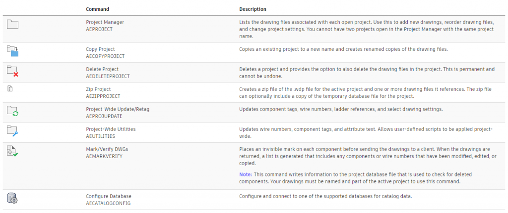
AutoCAD Electrical has a project manager tab, to manage all your electrical projects with tools to make projects active, customise, copy, delete and archive.

There are also buttons to refresh a drawing list, tasks list, update/retag and other file management tools.

Click here to learn more.

Project Tab

SQL Database

AutoCAD Electrical manages the catalog through a SQL database, giving users the ability to work with catalog database tables, with a detailed list of customisable Family Code/Table Names

SQL Database 2 Family Table Moving at the Speed of Business

Schematic Components

Using the schematic tools, an AutoCAD Electrical user can:

  • Search for AutoCAD component
  • Insert a component
  • Insert at Fence Crossing Points
  • Copy Data from One-line to Schematic
  • Copy Component
  • Copy Component at Fence Crossing Points
  • Insert from User-Defined Pick List
  • Insert from Equipment List
  • Insert Components or Terminals from Panel Lists
  • Cut, Copy, and Paste Electrical Objects
  • Scoot Components/Wire Segments
  • Align Components/Wire Numbers
  • Stretch PLC Modules, Components, or Blocks
  • Split PLC Modules/Components
  • Reverse/Flip Components
  • Swap Contact States
  • Work With Cross-Referencing
  • Surf on Cross-Reference Exception Reports
  • Change Cross-Reference Visibility
  • Insert a Location Box
  • Retag Components
  • Retrieve the Pinlist Values from a Peer Parent
  • Check the Coil/Contact Count


Circuits

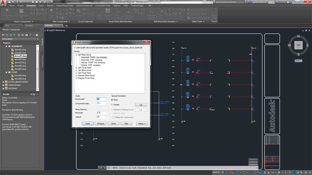
Circuits can be cut, copied and pasted and users can insert, configure single and dual circuits.

Using the circuit builder, the program builds dynamically and matches the rung spacing, adds wiring between components, and can annotate the circuit with calculated values based upon the assigned load amperage of the circuit. Circuit Builder extracts these annotation values from a database based on engineering standards, motor horsepower, and supply voltage.

Circuits

PLC

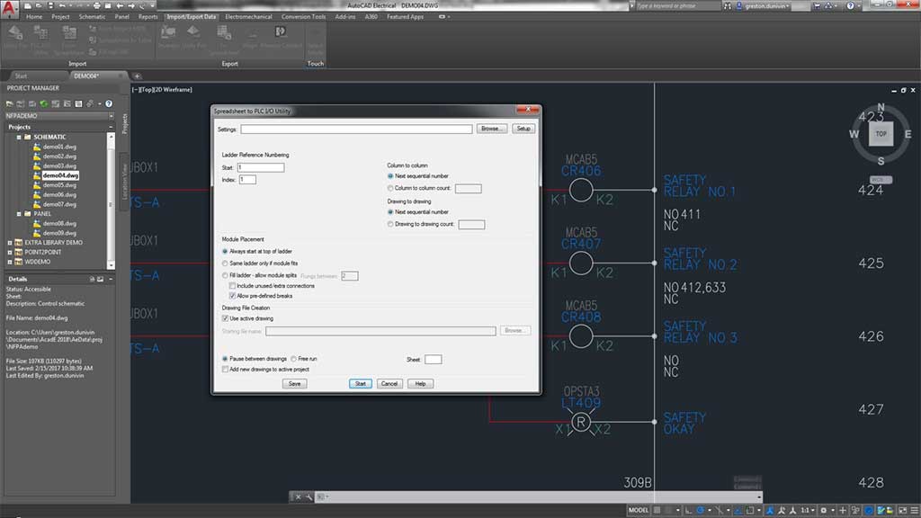
AutoCAD Electrical toolset can generate any number of different PLC I/O modules on demand and in various graphical styles. AutoCAD Electrical toolset generates the selected PLC I/O module through a parametric generation technique based on information in the PLC database (ACE_PLC.MDB).

PLC

Wires and Wire Numbers

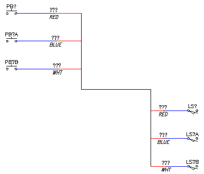
Create, import, select, and change wire types with AutoCAD Electrical using the schematic tab for:

  • Different Wire Types
  • Ladders
  • Wire Gaps
  • Single Arrows
  • Tee MArkers
  • Wire Sequence
  • Internal Jumpers
  • Wire Colour/Guage Labels
  • In-Line Wire Labels
  • Inserting Cable Markers
  • Fan In/Out Source and Destination Markers
  • Shield Symbols
  • Inserting Wire Numbers
Wires and Wire Numbers

Terminals

Terminals can be inserted from the Catalog browser and users of AutoCAD Electrical can define a Multi-Level Terminal by Catalog Value, by Terminal Block Properties, and associate Terminals on the same Drawing or across Drawings.

When selecting a terminal, the user can show terminal associations or break them apart.

Terminals

Catalog

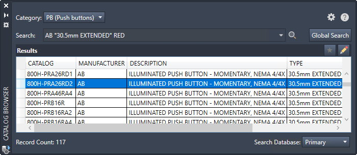
When working in the Catalog browser in AutoCAD Electrical, the user has a the ability to:

  • Insert a Schematic Component From the Catalog
  • Assign Catalog Information to a Component
  • Predefine a Search Value for Catalog Browser Lookup Mode
  • Copy Catalog Assignments
  • Show Missing Catalog Assignments
  • Update Components from the Catalog Database
  • Work With Editing the Catalog Database Records
  • Work With Catalog Database Tables
  • Create a Project-Specific Catalog Database
  • Define a Secondary Catalog Lookup File for a Project
  • Move the Catalog Database File
  • Edit or Add Manufacturer Content to the Catalog Database
  • Search through the Catalog


Catalog

Panel Layout

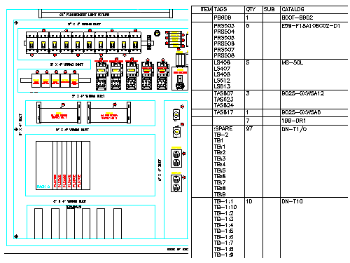
The Panel Layout tools create intelligent mechanical / panel layout drawings, whereby:

  • Layouts can be driven from information carried on the AutoCAD Electrical toolset schematic wiring diagram drawings or they can be constructed independently of schematics.
  • AutoCAD Electrical toolset places no requirements on special naming or attribute requirements on mechanical footprint symbols. Vendor-supplied footprint symbols, in AutoCAD format, can be used as is with AutoCAD Electrical toolset.
  • Bi-directional update capabilities allow certain schematic wiring diagram edits to update the panel drawings automatically and vice versa.
  • Wire number, wire color/gauge information, and connection sequencing data can be extracted directly from the schematics and annotated on to the panel footprint representations.
  • AutoCAD Electrical toolset extracts various reports from these smart panel layout drawings including panel BOM, panel component/item lists, nameplate reports, and schematic versus panel exception reports.
Panel Layout

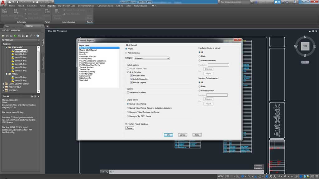
Reports

Users can generate reports based on the schematic design with the ability to:

  • Generate a report
  • Insert a report on to a drawing
  • Change the format of a report
  • Export the report to a spreadsheet


Reports

Symbol Libraries

During a stand-alone installation of AutoCAD Electrical, all available symbol libraries are installed and users can remove any symbol libraries not required.

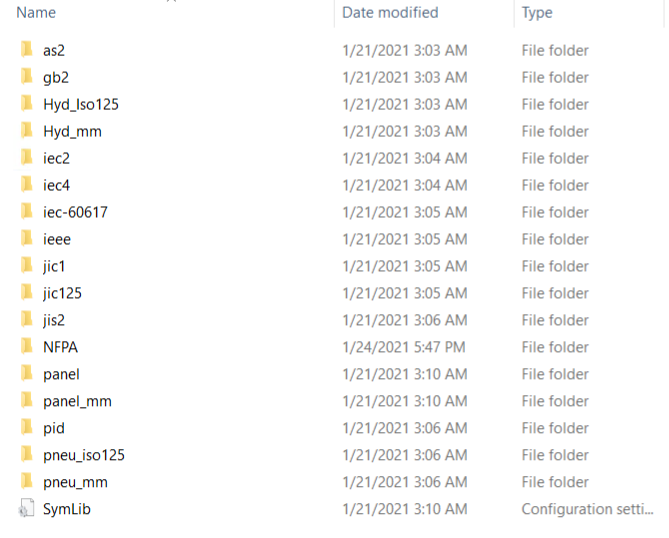
The symbol libraries and Symbol Builder template files are located at C:\Users\Public\Documents\Autodesk\Acade {version}\Libs. The symbol library subfolder, \Libs, carries various AutoCAD Electrical schematic and panel layout symbol libraries.

The following electrical schematic libraries are installed by default and multiple symbol libraries can be used within a project.

Symbol Libraries

Electromechanical Projects

The Panel Layout tools create intelligent mechanical / panel layout drawings, whereby:

  • Layouts can be driven from information carried on the AutoCAD Electrical toolset schematic wiring diagram drawings or they can be constructed independently of schematics.
  • AutoCAD Electrical toolset places no requirements on special naming or attribute requirements on mechanical footprint symbols. Vendor-supplied footprint symbols, in AutoCAD format, can be used as is with AutoCAD Electrical toolset.
  • Bi-directional update capabilities allow certain schematic wiring diagram edits to update the panel drawings automatically and vice versa.
  • Wire number, wire color/gauge information, and connection sequencing data can be extracted directly from the schematics and annotated on to the panel footprint representations.
  • AutoCAD Electrical toolset extracts various reports from these smart panel layout drawings including panel BOM, panel component/item lists, nameplate reports, and schematic versus panel exception reports.

Vault Professional Integration

Vault Professional support AutoCAD Electrical .wdp project files where you can add and open an AutoCAD Electrical project to/from Vault using the .wdp file format and use the usual check in/out, revision/lifecycle and search features.

Autodesk Vault Professional allows you to:

  • Keep a history of your design changes
  • Review how your designs have progressed
  • Rollback to a previous version
  • Have a central shared secured repository of drawings and data
  • Search for required information across multiple drawings and projects
Vault Professional Integration. Autodesk Vault Professional Training Course

What's new in AutoCAD Electrical 2023

Whats New In Autocad Electrical 2023

Discover the Right CAD Tool for Your Engineering Needs

Choosing between AutoCAD and AutoCAD Mechanical? Our free eBook offers a detailed comparison to help you make the best choice for your design projects. Gain insights into key features, pricing, and real-world applications.

Download the eBook now to make an informed decision and optimise your workflow.

Get in Touch

DC is an authorised Autodesk Reseller providing products and services for the Architecture, Engineering, Construction, Infrastructure and Manufacturing Sectors.

Feel free to contact us on 1800 490 514, [email protected], by live chat or fill out the form below.

Contact Form Demo

VIEW MORE

Inventor and Revit Fabrication Workflows

Advance Steel Revit Workflows Moving at the Speed of Business
Inventor Revit interop Moving at the Speed of Business Inventor users working with Revit have always found the data exchange tedious, with huge Revit models taking time to import, naming conventions not coming through, only an Element ID, and then once this bloated model came through, having to work with your assembly and the imported Revit model, working at a snails pace, but that all changed when Autodesk introduced Revit rvt files being supported in AnyCAD, a file reference tool in Autodesk Inventor.

Revit to Inventor

inventor 2022 image factory dataset 02 Moving at the Speed of Business When importing a Revit rvt file, the Inventor user has the option to:
  • Import it (convert it to an Inventor model) or
  • Reference it (link it in, like an xref), so if the rvt file changes, it will update
Once you reference the file in, you can start modelling around it or place it in an existing assembly and detail it. Inventor Revit 1 Moving at the Speed of Business Inventor Revit 2 Moving at the Speed of Business Click here to learn more or enquire below.

Get in Touch

DC is an authorised Autodesk Reseller providing products and services for the Architecture, Engineering, Construction, Infrastructure and Manufacturing Sectors. Feel free to contact us on 1800 490 514, [email protected], by live chat or fill out the form below.
Contact Form Demo

VIEW MORE

Autodesk Fabrication Suite

autodesk fabrication product icon 128 Moving at the Speed of Business

Autodesk Fabrication Suite

Autodesk Fabrication Product Suite Text Banner

Fabrication ESTmep™, CADmep™ and CAMduct™ software provide an integrated set of tools for MEP speciality contractors to estimate, detail and drive fabrication of mechanical building systems.

Overview

Fabrication ESTmep™, CADmep™ and CAMduct™ software is a set of integrated tool for MEP estimators, engineers, designers and fabricators that works with Revit to connect MEP fabrication software to BIM.

  • Estimate more accurately and faster with manufacturer-specific content.

  • Design with more detail and accuracy

  • Connect to machines and create flat patterns

ESTMep, CADmep and CAMduct Overview

Estimating

Gain insight into project costs with cost analysis and reporting and generate competitive bids.

Detailing

Create fabrication-intent models of piping, plumbing and ductwork systems.

Fabricating

Produce sheet metal components and control the manufacturing production line.

Features

ESTmep Features

autodesk fabrication estmep product icon Moving at the Speed of Business

BIM and CAD import for bid generation

Extend design intent models from Revit and AutoCAD software into Fabrication ESTmep for more accurate, competitive bids.

Value engineering option tools

Show clients multiple service pricing options.

Accelerate underlay trace takeoff

Create more competitive bids quicker with design line.

Color-coded cost tool

Visualize job cost and cost analysis by color.

Manufacturer content database

Select from thousands of manufacturers’ items and pattern templates, including 54 imperial ranges, with real-world pricing and cost data for accurate estimating and analysis. Built-in Harrison codes and pricing.

Enhanced database export/import

Single-command database export and import, with optional insulation specifications and sections.

Iterative value engineering tools

Perform value engineering on services more efficiently, and produce several cost/benefit options for your clients.

Project tracking tools

Record all Adds and Omits on a job to support traceability and promote accountability for changes. Analyze this data to make comparisons against the original estimate.

Cost analysis, reporting, and estimating

Get accurate and clear information about model items, like ducts and pipes, and export data to inform effective cost analysis and estimating.

CADmep Features

Autodesk Fabrication CADmep Training Fundamentals Course

Detailed 3D modeling

Create fabrication-ready models of piping, plumbing, and ductwork systems.

Specification content modeling

Draw with real components and connections from thousands of manufacturer content items and pattern templates.

Extend design intent models

Easily import data from Revit and AutoCAD to lengthen the lifecycle of design models and help reduce model redundancy.

3D spooling capabilities

Create detailed fabrication shop spool sheets and bill of materials (BOM).

Service validation, clash detection

More effectively identify and resolve service issues before fabrication.

Costing and reporting

Quickly and easily obtain accurate information about model items and export data for better decision making.

CAMduct Features

autodesk fabrication camduct product icon 128 Moving at the Speed of Business

Sheet metal component library

Use an expansive specification-driven database of parametric components for detailing sheet metal.

Sheet metal component library

Use an expansive specification-driven database of parametric components for detailing sheet metal.

Material-specific nesting parameters

Set nesting parameters for different materials, such as insulation, ductboard, and sheet metal, to help avoid nesting the job multiple times.

Bar coding and QR coding

Add data-rich bar codes and QR codes to labels and worksheets.

Simple graphical interface

An easy-to-use graphical user interface (GUI) allows both novice and experienced software users to enter job data and edits.

Advanced job costing tools

Estimate jobs based on a variety of project factors to better understand the bottom line.

NC writing and machine support

With post processors built in to support a variety of machine types, CAMduct helps control your production line of any size.

Annual Subscription

Annual Subscription

Annual Subscription

Contact Us

If you would learn more about Autodesk software, please contact us by calling on 1800 490 514, by filling out the form or clicking the live chat in the bottom right-hand corner.

Contact Us Moving at the Speed of Business

VIEW MORE

Autodesk Fabrication Products

DSI fabrication 3693 Moving at the Speed of Business
Autodesk Fabrication Products banner Moving at the Speed of Business

Autodesk has various fabrication software products for manufacturing, architectural construction, HVAC and structural steel applications

Get Fabrication design and analysis software, connect machines, centralise data, connect systems and departments or use our professional services.

Design

Product types and features

Machining

Connect machines to design data

Simulation

Anlalyse structures and optimise designs
cube blk 400 Moving at the Speed of Business
Design
Product types and features
Machining 400 Moving at the Speed of Business
Machining
Connect machines to design data
Simulation 400 Moving at the Speed of Business
Simulation
Anlalyse structures and optimise designs
Services 400 Moving at the Speed of Business
Services
Training, setup, CNC posts, deployment, programming, etc.

Workflows

Workflows between products and systems

Systems

Data management, automation, collaboration, erp/crm, IoT and commerce systems

Services

Training, setup, CNC posts, deployment, programming, etc.
Workflows 400 Moving at the Speed of Business
Workflows
Workflows between products and systems
Access anywhere Moving at the Speed of Business
Systems
Data management, automation, collaboration, erp/crm, IoT and commerce systems

Interactive Map

Use our interactive maps, hover on an object below to learn more about Autodesk Fabrication products and Design Consulting's services.

Interactive Map
Use our interactive maps, hover on an object below to learn more about Autodesk Fabrication products and Design Consulting's services.
Autodesk Fabrication Product DC Ecosystem of products, systems and services from Design Consulting

Explore | Simulation Page

cube blk 400 Moving at the Speed of Business

Design

Autodesk fabrication products range from HVAC systems, structural steel, mechanical to architectural design

Interactive Maps

Explore products, systems, workflows and services for Fabrication.

Compare

Compare Fabrication Design and Machining Products

Advance Steel

AEC Collection

Inventor Pro

PD&M Collection

Fusion 360

Fusion Nesting

Interactive Map
Hover on an object below to learn more about Autodesk Fabrication design products
Autodesk Fabrication Products - design products for all types of fabrication

Structural steel detailing and fabrication tool built on AutoCAD.

Explore | Advance Steel Page

Complete toolset for Fabrication in Construction. Combine Advance Steel, CADmep, Revit, Point Layout, AutoCAD, Civil 3D, Navisworks and more

Explore | Architecture Engineering and Construction Collection Page

Create fabrication-intent models of piping, plumbing and ductwork systems.

Explore | CADmep Page

Optimise and automate nesting with the Nesting & Fabrication Extension. Create optimised and associative multi-sheet layouts for cutting on CNC machines.

Explore | Fusion 360 Page

Professional-grade 3D mechanical, sheet metal design and frame design, documentation, and product simulation tools.

Explore | Inventor Professional Page

The first 3D CAD, CAM, CAE, and PCB tool of its kind, connecting your entire product development process into one cloud-based software with sheet metal design tools.

Explore | Fusion 360 Page

Combine Inventor Professional, Inventor CAM, Inventor Nesting, Nastran, Factory Design Utilities, Fusion 360, AutoCAD, Navisworks plus more in the Product Design & Manufacturing Collection.

Explore | Product Design & Manufacturing Collection Page

Machining 400 Moving at the Speed of Business

Machining

Autodesk offer the following solutions for connecting designs to CAM/CNC, plasma/laser cutters and beam line machines.

Interactive Maps

Explore products, systems, workflows and services for Fabrication.

Compare

Compare Fabrication Design and Machining Products

Machining Products

Advance Steel

AEC Collection

PD&M Collection

Fusion 360

Fusion Nesting

Interactive Map
Hover on an object below to learn more about Autodesk Fabrication machining
Autodesk Fabrication Products Machining web full Moving at the Speed of Business

Get Advance Steel, CADmep, Revit, Point Layout, Navisworks, AutoCAD and more.

ExploreAEC Collection Page

Structural steel detailing and fabrication tool built on AutoCAD. Produce DXF's for flat patterns and NC1 code for beam line machines.

Explore | Advance Steel Page

Import designs from CADmep, create flat patterns and prepare designs for machining

Explore | CAMduct Page

Setup and generate CNC posts for 2.5 and 3 axis machining and simulate toolpaths.

ExploreFusion 360 Page

Setup and generate CNC posts for 2.5 and 3 axis machining and simulate toolpaths. Add the Nesting and Fabrication extension to nest sheet metal parts and generate toolpaths for plasma and laser cutting machines.

ExploreFusion 360 Page

Setup and optimise nest tables and export to DXF

ExplorePD&M Collection Page

Get 5-axis integrated CAD/CAM with Inventor CAM in the Product Design & Manufacturing Collection 

Explore | Product Design & Manufacturing Collection Page

Combine Inventor Professional, Inventor CAM, Inventor Nesting, Nastran, Factory Design Utilities, Fusion 360, AutoCAD, Navisworks plus more in the Product Design & Manufacturing Collection.

Explore | Product Design & Manufacturing Collection Page

Professional-grade 3D mechanical, sheet metal design and frame design, documentation, and product simulation tools.

Explore | Inventor Professional Page

matrix 400 Moving at the Speed of Business

Compare Fabrication Design and Machining Products

Advance Steel

AEC Collection

Inventor Pro

PD&M Collection

Fusion 360

Fusion Nesting

  • CADmep
  • CAMduct
  • Advance Steel
  • AEC
  • Inventor Pro
  • PD&M
  • Fusion 360
  • Fusion w. Nesting
CADmepCAMductAdvance SteelAECInventor ProPD&MFusion 360Fusion w. Nesting
/year
2D Design
3D Modelling
HVAC
Plumbing
Piping
Costing
2D Detailing
Bill of Materials
Nesting
DXF
CNC Post
Sheet Metal
Frames
Design Automation
Drawing Automation
Ladders
Rails
Porta Buildings
Steel Connection Library
BuyBuyBuyBuyBuyBuyBuyBuy Now
Autodesk Fabrication CADmep Training Fundamentals Course

Fabrication CADmep

Autodesk Fabrication CADmep gives you the ability to create fabrication-intent models of piping, plumbing and ductwork systems. Connect CADmep with ESTmep, CADduct and Revit for complete end to end workflows.
Interactive Map
Hover on an object below to learn more about Autodesk Fabrication CADmep for design and explore machining, workflows, management systems and Design Consulting's services.
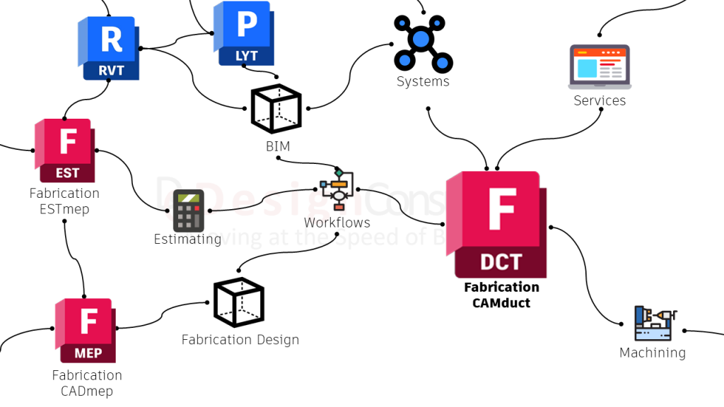
Autodesk Fabrication Products- cad-mep ecosystem and workflows of products and services

Import designs from CADmep, create flat patterns and prepare designs for machining

Explore | Fabrication CAMduct Page

Import designs from Revit and export estimating data to CADmep and CAMduct

Explore | Go to Fabrication CAMduct Page

Use Revit software to produce consistent, co-ordinated and complete model-based building designs and documentation for architectural, mep and structural construction projects

Revit Workflows Page | Revit Page

Autodesk Point Layout brings BIM coordinate systems to the jobsite. Connect building models to field construction workflows, with hardware compatibility including Leica, Topcon, Trimble, and more.

Point Layout Page

autodesk fabrication camduct product icon 128 Moving at the Speed of Business

Fabrication CAMduct

Create fabrication-intent models of piping, plumbing and ductwork systems.
Interactive Map
Hover on an object below to learn more about Autodesk Fabrication CADmep for design and explore machining, workflows, management systems and Design Consulting's services.
Autodesk Fabrication Products - CAMDuct - webfull

Import designs from CADmep, create flat patterns and prepare designs for machining

Explore | Go to Fabrication CAMduct Page

Import designs from Revit,  costing from ESTmep and send designs over to CAMduct to create flat patterns and prepare designs for machining

Explore | Go to Fabrication CADmep Page

Import designs from Revit and export estimating data to CADmep and CAMduct

Explore | Go to Fabrication ESTmep Page

Use Revit software to produce consistent, co-ordinated and complete model-based building designs and documentation for architectural, mep and structural construction projects

Revit Workflows Page | Revit Page

Autodesk Point Layout brings BIM coordinate systems to the jobsite. Connect building models to field construction workflows, with hardware compatibility including Leica, Topcon, Trimble, and more.

Point Layout Page

autodesk fabrication estmep product icon Moving at the Speed of Business

Fabrication ESTmep

Gain insight into project costs with cost analysis and reporting and generate competitive
Interactive Map
Hover on an object below to learn more about Autodesk Fabrication CADmep for design and explore machining, workflows, management systems and Design Consulting's services.
Autodesk Fabrication Products - ESTmep - web full

Gain insight into project costs with cost analysis and reporting and generate competitive bids.

Autodesk Fabrication ESTmep page

Import designs from CADmep, create flat patterns and prepare designs for machining

Explore | Go to Fabrication CAMduct Page

Import designs from Revit and ESTmep and send designs to CAMduct for manufacturing

Explore | Go to Fabrication CADmep Page

Use Revit software to produce consistent, co-ordinated and complete model-based building designs and documentation for architectural, mep and structural construction projects

Revit Workflows Page | Revit Page

Advance Steel structural steel fabrication, design and detailing software

Advance Steel

Steel detailing software that features a library of intelligent parametric elements, steel connections and plates for steel detailing and fabrication.
Interactive Map
Hover on an object below to learn more about Autodesk Advance Steel for design and explore machining, workflows, management systems and Design Consulting's services.
Autodesk Fabrication Products - Advance Steel - structural steel detailing and machining software

Steel detailing software features a library of intelligent parametric elements, steel connections and plates for steel detailing and fabrication.

Advance Steel Page

Use Revit software to produce consistent, co-ordinated and complete model-based building designs and documentation for architectural, mep and structural construction projects

Revit Workflows Page | Revit Page

Architecture Engineering and Construction Collection

Combine Advance Steel and CADmep with Revit, AutoCAD, Navisworks, Docs, Point Layout and more.
Interactive Map
Hover on an object below to learn more about Autodesk AEC Collection for design and explore machining, workflows, management systems and Design Consulting's services.
Autodesk Fabrication Products - AEC Collection workflows with BIM, Revit, CADmep, Advance Steel, DOCS and Robot Structural Analysis

Document Management and Collaboration for Construction Projects

Autodesk Construction Cloud Page

Get Advance Steel, CADmep, Revit, Point Layout, Navisworks, AutoCAD, Robot Structural Analysis and more.

AEC Collection Page

Structural load analysis software that verifies code compliance and uses BIM-integrated workflows to exchange data with Revit and Advance Steel.

AEC Collection Page

Use Revit software to produce consistent, co-ordinated and complete model-based building designs and documentation for architectural, mep and structural construction projects

Revit Workflows Page | Revit Page

Steel detailing software features a library of intelligent parametric elements, steel connections and plates for steel detailing and fabrication.

Advance Steel Page

Import designs from Revit and ESTmep and send designs to CAMduct for manufacturing

Explore | Go to Fabrication CADmep Page

Autodesk Point Layout brings BIM coordinate systems to the jobsite. Connect building models to field construction workflows, with hardware compatibility including Leica, Topcon, Trimble, and more.

Point Layout Page

Product Design & Manufacturing Collection

Combine Inventor Professional, Inventor CAM, Inventor Nesting, Nastran, Fusion 360 with AutoCAD, Navisworks and more.
Interactive Map
Hover on an object below to learn more about Autodesk PDM Collection for design and explore machining, workflows, management systems and Design Consulting's services.
Autodesk Fabrication Product PDM Collection Moving at the Speed of Business

Get Inventor Pro, CAM, Nesting, Nastran, Fusion 360, AutoCAD Mechanical, Electrical, Navisworks and more.

PDM Collection Page

Non-Linear FEA, thermal and Dynamic Simulation

PDM Collection Page

3D CAD, sheet metal tools, 2.5/3 axis CAM. Synch Fusion 360 and Inventor Models with AnyCAD.

ExploreFusion 360 Page

3D CAD with sheet metal and frame tools with linear and dynamic simulation. Synch 3D Fusion 360 models with  AnyCAD. Integrated CAM and Nesting in the PDM Collection.

ExploreInventor Professional Page

Optimise Nesting jobs, work with dwg, dxf or Inventor files in the PDM Collection.

PDM Collection Page

5-axis Integrated CAM and simulate toolpaths with Inventor Professional in the PDM Collection.

PDM Collection Page

Autodesk Inventor Professional 3D mechanical CAD software

Inventor Professional

3D CAD product, mechanical and fabrication design analysis and 2D detailing software
Interactive Map
Hover on an object below to learn more about Autodesk Inventor Professional for design and analysis. Explore workflows, management systems and Design Consulting's services.
Autodesk Fabrication Products Inventor Professional Moving at the Speed of Business

3D CAD with sheet metal and frame tools with linear and dynamic simulation. Synch 3D Fusion 360 models with  AnyCAD. Integrated CAM and Nesting in the PDM Collection.

Inventor Professional Page

Non-Linear FEA, thermal and Dynamic Simulation

PDM Collection Page

3D CAD, sheet metal tools, 2.5/3 axis CAM. Synch Fusion 360 and Inventor Models with AnyCAD.

ExploreFusion 360 Page

Get Inventor Pro, CAM, Nesting, Nastran, Fusion 360, AutoCAD Mechanical, Electrical, Navisworks and more.

PDM Collection Page

Optimise Nesting jobs, work with dwg, dxf or Inventor files in the PDM Collection.

PDM Collection Page

5-axis Integrated CAM and simulate toolpaths with Inventor Professional in the PDM Collection.

PDM Collection Page

Fusion 360

3D CAD/CAM product, mechanical and sheet metal design and 2D detailing software with extensions for fabrication, machining, simulation and generative design.
Interactive Map
Hover on an object below to learn more about Autodesk Fusion 360 for design, machining and analysis. Explore workflows, management systems and Design Consulting's services.
Autodesk Fabrication Products Fusion 360 and Extensions Moving at the Speed of Business

3D CAD, sheet metal tools, 2.5/3 axis CAM. Synch Fusion 360 and Inventor Models with AnyCAD. Add Extensions for further functionality.

Fusion 360 Page

Optimise and analyse designs for 3D printing

Fusion 360 Page

Non-Linear FEA, thermal and Dynamic Simulation

Fusion 360 Page

Optimise products with generative design and analysis tools.

Fusion 360 Page

3D CAD with sheet metal and frame tools with linear and dynamic simulation. Synch 3D Fusion 360 models with  AnyCAD. Integrated CAM and Nesting in the PDM Collection.

ExploreInventor Professional Page

Get Inventor Pro, CAM, Nesting, Nastran, Fusion 360, AutoCAD Mechanical, Electrical, Navisworks and more.

ExplorePDM Collection Page

5-axis Integrated CAM and simulate toolpaths.

Fusion 360 Page

Optimise Nesting jobs, create toolpaths for plasma/laser cutters, work with dwg, dxf or Fusion 360 files.

Fusion 360 Page

Simulation

Discover the range of simulation software for Fabrication products
Interactive Map
Hover on an object below to learn more about Autodesk simulation. Explore workflows, management systems and Design Consulting's services.
Autodesk Fabrication Products - Simulation

Heat transfer, drop test, advanced material models, linear statics, bolt connectors, CFD interoperability, response spectrum analysis,  structural analysis, linear buckling, static fatigue, surface contact.

ExplorePDM Collection Page

Get Inventor Pro for linear FEA and Nastran for Non-Linear FEA, thermal and dynamic simulation

PDM Collection Page

Linear FEA, motion analysis and dynamic simulation.

ExploreInventor Professional Page

Explore structural, thermal and explicit simulation tools, including injection moulding, for manufacturing insights.

ExploreFusion 360 Page

Structural load analysis software that verifies code compliance and uses BIM-integrated workflows to exchange data with Revit and Advance Steel.

ExploreAEC Collection Page

Get Robot Structural Analysis Professional, Advance Steel, Revit and more.

ExploreAEC Collection Page

Workflows 400 Moving at the Speed of Business

Workflows

Explore the workflows between fabrication products and systems
Interactive Map
Hover on an object below to learn more about Autodesk simulation. Explore workflows, management systems and Design Consulting's services.
Autodesk Fabrication Products Workflows Moving at the Speed of Business

CAD software for HVAC, piping, tubing, sheet metal, structural steel, product and mechanical design 

Explore

Use estimating software for mep, run scripts in Inventor Professional to calculate cost or get an Autodesk Industry Collection and use Navisworks for 2D/3D Quantity Takeoffs

Estimating Page

From HVAC, to NC1 for beamline machines, to 5-axis CAM post to Nesting toolpaths of exports to DXF

Explore

Data management, collaboration, construction management, product or layout configurators and CRM/ERP can all be connected to design, machining, estimating and simulation software.

Explore

Get training, custom scripts or applications, templates, content, systems deployed or connected.

Explore

Structural load analysis and  mechanical design and motion analysis software

Explore

BIM Software and systems to connect models, drawings and metadata.

BIM Page

Access anywhere Moving at the Speed of Business

Systems

Systems connect files, information, departments and people and increase productivity by creating end to end workflows between departments, automating processes, reduce double data entry and provide holistic visibility on data and projects.
Interactive Map
Hover on an object below to learn more about Systems for Fabrication products and explore design, machining, workflows and Design Consulting's services.
Autodesk Fabrication Products - Systems

Vault manages versions, revisions, lifecycles with automated reference management, file numbering schemes and tools to speed up file and folder management.

Vault Page

Customer Relationship and Enterprise Resource Management software to manage records of company, contacts, quotes, inventory, costs, and projects with tools for sales, marketing and operations.

CRM/ERP Page

Cloud file sharing platform with low-latency for synching large datasets between people.

Egnyte

Connect product and layout configurators to your website, CRM/ERP or data management systems.

Visualisation Page

PDF Collaboration, mark-up, measure and quantity take off for 2D and 3D PDF's with add-ins for AutoCAD and Revit.

Bluebeam Page

Construction management software for mark-up, measure, RFI's, issues, compare, bids, costing, take-offs and more.

Construction Cloud Page

File and metadata automation, analytics and access system for Revit and AutoCAD-based projects such as AutoCAD, Civil 3D, Plant 3D Advance Steel and CADmep/ESTmep/CAMduct with the ability to connect to construction management systems such as Autodesk Construction Cloud/BIM 360, ProjectWise, ProCore and cloud sharing platforms such as Egnyte, SharePoint, Dropbox, Google Drive and more.

Clarity Page

Services 400 Moving at the Speed of Business

Services

Design Consulting provides a range of services for Autodesk Fabrication products such as CNC posts for CAMduct, Inventor CAM and Fusion 360, drawing templates, content creation, training, system deployments, programming and more.
Interactive Map
Hover on an object below to learn more about Services for Fabrication products and explore design, machining, workflows and Design Consulting's services.
Autodesk Fabrication Products services Moving at the Speed of Business

Drawing and model templates and content creation (Duct & piping libraries, structural steel libraries and connections, Content Center libraries and Revit Families), drawing styles and standards and sheet metal templates.

Services Page

CNC posts and toolpaths to connect design to machines for CAMduct, Inventor CAM, Fusion 360 and Fusion 360 Nesting Extension

Services Page

LISP routines, AutoCAD scripts, Inventor iLogic scripts, Revit macros, Dynamo scripts PyRevit scripts and custom integrations and applications.

Programming Page

Design, analysis and visualisation Contractor Services

Contractor Services Page

Structured or customised training courses.

Training Page

Get in Touch

Contact Form Demo

VIEW MORE

What’s New in Advance Steel 2022

Advance Steel 2022 Select Objects for Camera Detailing Moving at the Speed of Business

What's New in Autodesk Advance Steel 2022

Advance Steel 2022 has new features and improvments in the following areas:

  • Modelling Tools
  • Documentation
  • Interoperability
  • Localisation

Modelling Tools

New Home screen

The new home screen is located under the start tab and shows the most recently used files, is customisable, provides access to Autodesk Docs, learning resources, help, forum, support and has a refresh button to view any project folder updates.

Maintain Hole Positions during Beam Sketch

  • Control how the holes placement reacts to beam or column stretching
  • New default under the Beam category in the Management Tools
  • If activated, hole positions remain unchanged
  • Works if you stretch, trim, extend, or lengthen the steel member containing these holes

New Dynamo Nodes

  • Additional nodes for beams creation:
  • Poly-beams
  • Unfolded beams
  • Nodes for the creation of steel connection components:
  • Bolts / Anchors / Shear studs
  • Nodes to read and write properties
  • Utility nodes
  • Library of sample Dynamo files

Documentation

Drawing Labeling Enhancement

Advance Steel 2022 has improvements with the display of leader lines on drawings. Users can now attach a leader line at the middle of the text and can also include a horizontal landing line and the leader line can be configured in the Management tools.

Under the Drawing-Labelling category, there are new options to define the attachment position and choose whether labels are to be created with or without a horizontal line.

Camera Enhancements

  • Use cameras to create views on 2D drawings
  • Control which objects you would like to include in these camera views
  • New Select objects for camera tab
  • Use the Mark objects button to highlight the selected elements in red
  • Utilize a drawing process to automate the creation of drawings based on these cameras

Drawing Explode Enhancements

  • Use the batch explode feature in the Document Manager to explode Advance Steel drawings to pure AutoCAD drawings
  • New options for callouts in the Detail Explode settings dialog box:
  • Callout symbol
  • Callout title
  • Specify the layer, color and line type to be used when exploding the drawings
  •  

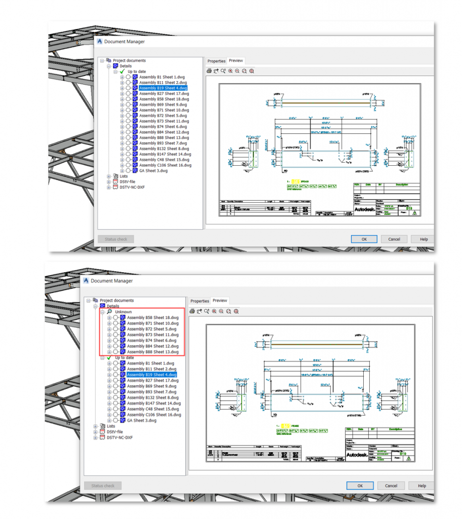
Document Management Changes to Drawing Registration

  • If a drawing is moved away from the Details subfolder next to the model DWG file:
  • It is relocated to the “Unknown” branch of the Document Manager
  • The option to open the shop drawing via the contextual menu is not available
  • The drawing number is empty in Model Browser
  • When the drawing is moved back to the correct location, everything returns to normal

One-side DXF Files for Plates

  • Control the number of sides described in NC-DXF files for plates
  • New default Create one-side only for plate DXF output to activate in the Management Tools
  • Other default to define the suffix of the file name in case both plate sides is necessary

Interoperability

Advance Steel 2022 Extension for Revit*

  • Share LOD 350 model information bidirectionally between Revit and Advance Steel
  • Transfer steel members & connections
  • Import / export / synchronise changes between Revit 2022 and Advance Steel 2022

Push PDF Layouts to Autodesk Docs

  • New commands to open (and close) the Push to Autodesk Docs palette:
  • PUSHTODOCSOPEN
  • PUSHTODOCSCLOSE
  • Select Advance Steel DWG drawings
  • Select a project folder on Autodesk Docs to publish these layouts to PDFs
  • View, review, comment on Autodesk Docs

Shared Views

  • Share 3D views and 2D drawings of your Advance Steel project with other stakeholders
  • View, comment and mark up the results in a web browser
  • View and response to comments and markups directly in Advance Steel
  • Introduced with Advance Steel 2019 in the AEC Collection, this feature is now also available for current standalone Advance Steel users

Localisation

Improvements to Drawing Styles for Australia

  • Enhanced dimension holes configurations for cleaner drawings (assemblies with attached plates or gussets)
  • Additional drawing styles for creating steel assemblies such as trusses

Contact Us

If you would learn more about Autodesk software, please contact us by calling on 1800 490 514, by filling out the form or clicking the live chat in the bottom right-hand corner.

VIEW MORE