1800 490 514 [email protected]

Optimising Product Designs with Autodesk Inventor Nastran

Autodesk Inventor Nastran

Optimising Product Designs with Autodesk Inventor Nastran

Imagine a world where product designs are perfected before they ever reach the prototyping stage. Engineers and designers can foresee and resolve potential issues early, ensuring their creations are innovative, reliable, and cost-effective. This is the transformative potential of simulation-driven design, made possible by Autodesk Inventor Nastran.

The importance of early-stage simulation is underscored by an Aberdeen Group report, which reveals more than half of the respondents preferred to consolidate their simulation vendors in the early stage with powerful virtual simulation tools like Autodesk Inventor Nastran. 

In this blog post, let’s delve into Autodesk Inventor Nastran, exploring its benefits, capabilities, and the ways it is reshaping the future of product development.

What is Autodesk Inventor Nastran?

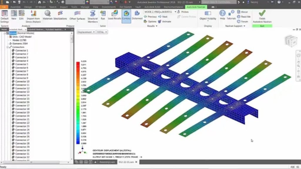
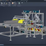
Autodesk Inventor Nastran is a powerful finite element analysis (FEA) tool integrated directly into Autodesk Inventor CAD software. It enables designers and engineers to perform a wide range of simulation studies on their product designs, helping them optimise performance, reduce development time and costs, and deliver higher-quality, more reliable products.

FEA is a numerical technique used to analyse the behaviour of complex structures and systems under various loads and conditions. By creating a digital model of a product and subjecting it to simulated stresses, forces, and other environmental factors, engineers can gain valuable insights into how the design will perform in the real world.

Inventor Nastran seamlessly integrates this powerful FEA technology into the Inventor CAD environment, allowing designers to analyse and optimise their designs without leaving the familiar Inventor interface. This streamlined workflow eliminates the need to switch between multiple software tools, saving time and improving productivity.

What Types of Simulation Studies Can Be Performed with Inventor Nastran?

Inventor Nastran allows you to conduct a variety of simulation studies, including:

. Linear, Prestress, and Nonlinear Static Analysis :

Understand how your design will respond to various static loads and stresses.

. Normal and Prestress Modes :

Analyse the natural vibration modes of your design, including the effects of prestress.

. Linear and Nonlinear Buckling : 

Identify potential buckling issues that could compromise the structural integrity of your design.

. Direct, Modal, and Nonlinear Transient Response : 

Simulate the dynamic behaviour of your design under time-varying loads.

. Impact Analysis : 

Assess how your design will withstand sudden impacts or collisions.

. Direct, Modal Frequency Response : 

Understand how your design will respond to harmonic excitations.

. Random Response : 

Analyse the response of your design to random vibrations.

. Shock/Response Spectrum : 

Simulate the effects of shock and vibration events on your design.

. Multi-Axial and Vibration Fatigue : 

Predict the fatigue life of your design under complex loading conditions.

. Linear and Nonlinear Steady State Heat Transfer : 

Analyse the thermal behaviour of your design.

. Nonlinear Transient Heat Transfer : 

Simulate the dynamic thermal response of your design.

. Explicit Dynamics: 

Perform advanced simulations of high-speed events, such as impacts or explosions.

. Explicit Quasi-Static : 

Analyse the behaviour of your design under quasi-static loading conditions.

These simulation capabilities enable you to thoroughly evaluate your product designs, identifying and addressing potential issues before they become costly problems during physical prototyping or manufacturing.

How Can Simulation Studies Help Optimise Product Designs?

Simulation studies with Autodesk Inventor Nastran help optimise product designs in several ways:

1. Identifying and Addressing Potential Issues :

Simulating the behaviour of your design under various loads and conditions uncovers potential problems, such as stress concentrations, deformations, or fatigue failures, allowing you to make informed design decisions and implement necessary changes before investing in physical prototypes.

2. Reducing Over-Engineering :

Simulation studies ensure your designs are fit for purpose by optimising material use and eliminating unnecessary features or components. This not only reduces manufacturing costs but also improves the overall efficiency and performance of your products.

3. Accelerating the Design Process: 

Rapid design iterations and simulations save time and resources compared to physical prototyping and testing. By identifying and resolving issues early in the design phase, you can significantly shorten the product development cycle and bring your innovations to market faster.

4. Improving Product Quality and Performance : 

Informed design decisions based on accurate simulation results lead to better-performing and more reliable products. This can translate into increased customer satisfaction, reduced warranty claims, and a stronger competitive position in the market.

5. Enhancing Collaboration and Communication : 

Simulation results can be easily shared with stakeholders, including cross-functional teams, management, and customers. This facilitates better decision-making, improves overall project management, and helps ensure that the final product meets all necessary performance and compliance requirements.

How Does Inventor Nastran Integrate with Autodesk Inventor?

Inventor Nastran is tightly integrated with Autodesk Inventor CAD software, allowing you to perform simulation studies directly within the Inventor environment. This streamlined workflow eliminates the need to switch between multiple software tools, saving time and improving productivity.

The integration also enables you to import and export results to and from other Autodesk applications, such as Autodesk CFD for fluid flow and thermal analysis, or Autodesk Moldflow for plastic part simulation. This cross-application integration ensures a comprehensive design validation process, helping you meet all necessary performance and compliance requirements.

By leveraging the synergy between Inventor Nastran and Inventor CAD software, you can create a seamless, end-to-end product development process that combines the power of simulation with the flexibility and ease of use of a leading CAD platform.

What Are the Benefits of Using Inventor Nastran for Product Design Optimisation?

Using Inventor Nastran for product design optimisation provides several key benefits:

1. Reduced Development Time and Costs :

Simulation studies help identify and address issues early in the design process, reducing the need for physical prototyping and testing. This can lead to significant cost savings and faster time-to-market for your products.

2. Improved Product Quality and Performance:

Accurate simulation results enable informed design decisions, leading to better-performing and more reliable products. This can translate into increased customer satisfaction, reduced warranty claims, and a stronger competitive position in the market.

3. Increased Innovation and Competitiveness : 

The ability to rapidly iterate and optimise designs allows you to bring innovative products to market faster than your competitors. By leveraging the power of simulation, you can explore more design options, test the limits of your ideas, and deliver truly differentiated products to your customers.

4. Enhanced Collaboration and Communication : 

Simulation results can be easily shared with stakeholders, facilitating better decision-making and improving overall project management. This helps ensure that the final product meets all necessary performance and compliance requirements while aligning with the needs and expectations of your customers.

What’s the Difference Between Inventor Professional and Autodesk Inventor Nastran?

While both products offer some similar features, there are some notable differences between them.
Linear stress analysis
Feature
Inventor Professional
Nastran In-CAD
Yes
Yes
Nonlinear stress analysis
Yes
Yes
Modal analysis
Yes
Yes
Buckling analysis
Yes
Yes
Thermal analysis
Yes
Yes
Fatigue analysis
Yes
Yes
Drop test analysis
Yes
Yes
Frequency response analysis
No
Yes
Random vibration analysis
No
Yes
Shock response spectrum analysis
No
Yes

In addition to these differences, there are also some differences in product licences. Autodesk Inventor Professional is available as a standalone product, allowing users to purchase it separately from other Autodesk software. In contrast, Autodesk Inventor Nastran In-CAD is only available as part of the Autodesk Product Design & Manufacturing Collection, which is a suite of design, engineering, and manufacturing tools that also includes Inventor Professional. This means that users who require the advanced analysis capabilities of Nastran In-CAD must also purchase the entire collection, which may be a consideration for some customers.

Unlock the Full Potential of Simulation-Driven Design

Inventor Nastran is a game-changer in product design optimisation. By harnessing the power of simulation, you can unlock new levels of innovation, reduce development costs, and deliver products that exceed customer expectations.

Do not settle for subpar designs or lengthy development cycles. Embrace the future of product design with Autodesk Inventor Nastran and revolutionise the way you bring your ideas to life. Get in touch with our team to learn more about Inventor Nastran and purchase the Autodesk PDM collection.

Contact Us

Contact us to find out how we can help your business. Fill out the form below, by live chat, phone or email.

P: 1800 490 514 |  E: [email protected]

Connected Design

Design Consulting Autodesk Gold Partner
about design consulting Moving at the Speed of Business

VIEW MORE

Design Consulting Promoted to Autodesk Gold Partner

Autodesk Gold Partner Autodesk Reseller AutoCAD, Inventor, Revit

Design Consulting Promoted to Autodesk Gold Partner

Autodesk Gold Partner Autodesk Reseller AutoCAD, Inventor, Revit

Autodesk has promoted Design Consulting to an Autodesk Gold Partner following continued growth since becoming an Autodesk Reseller in November, 2020.

Design Consulting would like to thank our customers, staff and Autodesk for all their support as we move at the speed of business!

Design Consulting provides tailored end to end solutions, expertise and specialisation in Autodesk’s offerings, aligning our solutions with our customers objectives and good old fashioned customer service.

Contact Us

Contact us to find out how we can help your business. Fill out the form below, by live chat, phone or email.

P: 1800 490 514 |  E: [email protected]

Connected Design

Design Consulting Autodesk Gold Partner
about design consulting Moving at the Speed of Business

autocad architecture vs autocad lt, AutoCAD LT vs AutoCAD architecture

VIEW MORE

The Ultimate Guide to AutoCAD vs AutoCAD Architecture

The Ultimate Guide to AutoCAD vs AutoCAD Architecture Toolset for architects and building designers. AutoCAD Architecture vs Revit

The Ultimate Guide to AutoCAD vs AutoCAD Architecture

AutoCAD architecture Moving at the Speed of Business

AutoCAD and AutoCAD Architecture are both powerful CAD software programs that can be used for a variety of purposes, including architectural design, engineering, and manufacturing. However, there are some key differences between the two programs that can make one a better choice for your specific needs.

In this blog post, we will compare AutoCAD and AutoCAD Architecture in terms of their features, capabilities, and pricing. We will also discuss the factors you should consider when choosing between the two programs.

What is AutoCAD?

AutoCAD is a general-purpose CAD software program that can be used for a variety of purposes, including architectural, mechanical, and electrical design. It offers a wide range of features and tools, making it a versatile option for many different industries.

Some of the key features of AutoCAD include:

  • 2D and 3D drafting
  • Dimensioning
  • Annotation
  • Rendering
  • Sheet metal design
  • Manufacturing
  • Import and export of CAD files

AutoCAD Architecture vs AutoCAD

AutoCAD is a general-purpose CAD software program that can be used to create 2D and 3D drawings. It includes a wide range of features for drafting, editing, and annotating drawings. AutoCAD also supports a variety of file formats, making it easy to share your drawings with others.

AutoCAD Architecture is a specialized CAD software program that is designed for architectural design. It includes a number of features that are specifically designed for creating architectural drawings, such as intelligent walls, doors, and windows. AutoCAD Architecture also includes a library of pre-built architectural objects, which can save you time and effort when creating your drawings.

AutoCAD architecture vs AutoCAD

Both AutoCAD and AutoCAD Architecture are capable of creating high-quality drawings. However, AutoCAD Architecture has a number of features that make it specifically suited for architectural design. These features include:

  • Intelligent objects: AutoCAD Architecture objects are intelligent, which means that they can be manipulated as a whole rather than as individual lines and curves. This makes it easier to create accurate and realistic drawings.
  • Architectural features: AutoCAD Architecture includes a library of pre-built architectural objects, such as walls, doors, and windows. This can save you time and effort when creating your drawings.
  • Parametric modeling: AutoCAD Architecture supports parametric modeling, which allows you to create objects that can be modified by changing their parameters. This can be useful for creating complex architectural objects.

With AEC3DPRINT command, you can natively export the AEC objects to an STL file format that's compatible with 3D printing without converting to 3D solids.

AutoCAD Architecture vs AutoCAD vs AutoCAD LT 

FeatureAutoCAD ArchitectureAutoCADAutoCAD LT
Intelligent objectsYesNoNo
Architectural featuresYesNoNo
Parametric modelingYesNoNo
2D drafting toolsYesYesYes
3D modeling toolsYesYesNo
Annotation toolsYesYesYes
Rendering toolsYesYesNo
SchedulesYesNoNo
Documentation toolsYesYesNo
Standards complianceYesNoNo
Collaboration toolsYesYesNo
Cloud integrationYesYesNo

AutoCAD Architecture has a number of unique commands that are specifically designed for architectural design. These commands include:

  • AECWALL: This command creates a wall object. Wall objects are intelligent, which means that they can be manipulated as a whole rather than as individual lines and curves. This makes it easier to create accurate and realistic walls.
  • AECDOOR: This command creates a door object. Door objects are also intelligent, and they can be customized to fit your specific needs.
  • AECWINDOW: This command creates a window object. Window objects are also intelligent, and they can be customized to fit your specific needs.
  • AECROOF: This command creates a roof object. Roof objects are also intelligent, and they can be customized to fit your specific needs.
  • AECSCHEDULE: This command creates a schedule. Schedules can be used to track the quantities of materials, labor, and equipment used in a project.
  • AECDOCUMENT: This command creates a document. Documents can be used to create drawings, reports, and presentations.
  • AECSTANDARDS: This command ensures that your drawings comply with industry standards.
  • AECCOLLABORATE: This command allows you to collaborate with other users on projects.
  • AECCLOUD: This command allows you to access your drawings and projects from anywhere.

In addition to these unique commands, AutoCAD Architecture also includes a number of other features that are specifically designed for architectural design. These features include:

  • A library of pre-built architectural objects
  • A number of parametric tools
  • A number of tools for creating and managing schedules
  • A number of tools for creating and managing documentation
  • A number of tools for ensuring that your drawings comply with industry standards
  • A number of tools for collaborating with other users on projects
  • Integration with the Autodesk cloud

Discover the Right CAD Tool for Your Engineering Needs

Choosing between AutoCAD and AutoCAD Mechanical? Our free eBook offers a detailed comparison to help you make the best choice for your design projects. Gain insights into key features, pricing, and real-world applications.

Download the eBook now to make an informed decision and optimise your workflow.

Tailored Functionality

Organisations can customise AutoCAD for their industries, empowering teams to build and run discipline-specific routines and workflows.

Download the Study here to learn how you can save over 60% in productivity using AutoCAD with Specialised Toolsets.

pdf icon

Autodesk AutoCAD 2024 Specialised Toolset Moving at the Speed of Business

Ready to get AutoCAD with the Architecture Toolset?

Get up to 20% Off Software or Services!

Contact us to find out how much money you can save on software, training or other services. Fill out the form below, by live chat, phone or email.

P: 1800 490 514 |  E: [email protected]

Connected Design

Buy Autodesk AutoCAD 2024

AutoCAD 2024 Brochures

PDF Icon
AutoCAD 2024 Brochure
PDF Icon
AutoCAD LT 2024 Brochure
PDF Icon
AutoCAD vs AutoCAD LT 2024

autocad architecture vs autocad lt, AutoCAD LT vs AutoCAD architecture

VIEW MORE

AutoCAD Map 3D: The Perfect Mapping Tool for Engineering and GIS Professionals

AutoCAD Map 3D is a powerful GIS software that allows CAD professionals to create, edit, and visualize geospatial data. It is a comprehensive toolset that includes everything you need to work with maps, 3D models, and other spatial data.
AutoCAD Map 3D GIS Mapping software

AutoCAD Map 3D: The Perfect Mapping Tool for Engineering and GIS Professionals

AutoCAD Map 3D is a powerful GIS software that allows CAD professionals to create, edit, and visualize geospatial data. It is a comprehensive toolset that includes everything you need to work with maps, 3D models, and other spatial data.

AutoCAD Map 3D is a geographic information system (GIS) software that is part of the AutoCAD family of products. It is designed for CAD professionals who need to work with geospatial data. AutoCAD Map 3D includes a comprehensive toolset for creating, editing, and visualizing maps, 3D models, and other spatial data.

Features and Benefits

AutoCAD Map 3D includes a wide range of features for working with geospatial data, including:

  • Data management tools for importing, exporting, and managing spatial data
  • 2D and 3D drafting tools for creating and editing maps and models
  • Visualisation tools for creating interactive maps and 3D models
  • Analysis tools for performing spatial analysis
  • Collaboration tools for sharing data and projects with others

There are many benefits to using AutoCAD Map 3D, including:

  • Increased productivity: AutoCAD Map 3D can help you save time and improve your workflow by providing a comprehensive toolset for working with geospatial data.
  • Improved accuracy: AutoCAD Map 3D can help you create more accurate maps and models by providing a variety of tools for data management, drafting, and visualisation.
  • Enhanced collaboration: AutoCAD Map 3D can help you collaborate with others more effectively by providing tools for sharing data and projects.
  • Increased flexibility: AutoCAD Map 3D is a flexible software that can be used for a variety of purposes, including engineering, construction, and environmental planning.

AutoCAD Map 3D Vs AutoCAD and AutoCAD LT

AutoCAD Map 3D is a more powerful and feature-rich version of AutoCAD than AutoCAD LT and AutoCAD. AutoCAD Map 3D includes all of the features of AutoCAD LT and AutoCAD, plus a number of additional features for working with geospatial data.

FeatureAutoCAD Map 3DAutoCAD LTAutoCAD
Data managementYesNoNo
2D and 3D draftingYesYesYes
VisualizationYesNoNo
AnalysisYesNoNo
CollaborationYesNoNo

The right version of AutoCAD for you depends on your specific needs. If you only need to:

  • Work with geospatial data, then AutoCAD Map 3D is the best choice.
  • Create basic 2D drawings, then AutoCAD LT is a good option.
  • Create basic 3D models or 2D drawings and don’t need any of the advanced features of AutoCAD Map 3D, then AutoCAD is the best choice.

Connecting AutoCAD Map 3D with other apps

AutoCAD Map 3D can be used with other Autodesk apps to create a more comprehensive and integrated workflow. For example, AutoCAD Map 3D can be used with AutoCAD Civil 3D to create 3D models of infrastructure projects. AutoCAD Map 3D can be used with Autodesk 3ds Max to create photorealistic renderings of maps and models.

AutoCAD Map 3D can be connected to a variety of GIS mapping data sources, including:

  • Shapefiles: Shapefiles are a common format for storing vector data. AutoCAD Map 3D can import and export shapefiles.
  • Geodatabases: Geodatabases are a powerful format for storing spatial data. AutoCAD Map 3D can connect to geodatabases hosted on a variety of platforms, including Microsoft SQL Server, Oracle, and IBM DB2.
  • Raster datasets: Raster datasets are a format for storing gridded data. AutoCAD Map 3D can import and export raster datasets.
  • Web services: Web services are a way to access spatial data over the internet. AutoCAD Map 3D can connect to web services that are hosted on a variety of platforms, including ArcGIS Online and Google Maps.

To connect AutoCAD Map 3D to a GIS mapping data source, you can use the following steps:

  1. Open AutoCAD Map 3D.
  2. Click the Map tab.
  3. In the Data Sources panel, click the Add button.
  4. Select the type of data source you want to connect to.
  5. Enter the connection information for the data source.
  6. Click the Connect button.

Once you have connected AutoCAD Map 3D to a GIS mapping data source, you can view and edit the data in AutoCAD Map 3D. You can also use AutoCAD Map 3D to perform spatial analysis on the data.

Here are some of the benefits of connecting AutoCAD Map 3D with GIS mapping data sources:

  • You can access a wider range of spatial data.
  • You can perform more complex spatial analysis.
  • You can share your work with others more easily.
  • You can collaborate with others more effectively.

If you need to work with geospatial data, then connecting AutoCAD Map 3D with GIS mapping data sources is a great way to improve your workflow and productivity.


Tailored Functionality

Organisations can customise AutoCAD for their industries, empowering teams to build and run discipline-specific routines and workflows.

Autodesk AutoCAD 2024 Specialised Toolset Moving at the Speed of Business

AutoCAD Map 3D 2024

Coordinate System Update

AutoCAD Map 3D 2024 supports the new coordinate systems in the following categories:

  • SnakeGrid EWR2
  • NAD83(CSRS) / Alberta 3TM

Refer to the 2024 Help file for further information 

Discover the Right CAD Tool for Your Engineering Needs

Choosing between AutoCAD and AutoCAD Mechanical? Our free eBook offers a detailed comparison to help you make the best choice for your design projects. Gain insights into key features, pricing, and real-world applications.

Download the eBook now to make an informed decision and optimise your workflow.

Ready to get AutoCAD 2024?

Discover how Autodesk AutoCAD 2024 can streamline your workflow, increase productivity, and optimise your design process. 

Get up to 20% Off Software or Services!

Contact us to find out how much money you can save on software, training or other services. Fill out the form below, by live chat, phone or email.

P: 1800 490 514 |  E: [email protected]

Connected Design

Buy Autodesk AutoCAD 2024

AutoCAD 2024 Brochures

PDF Icon
AutoCAD 2024 Brochure
PDF Icon
AutoCAD LT 2024 Brochure
PDF Icon
AutoCAD vs AutoCAD LT 2024

VIEW MORE

AutoCAD Mechanical vs AutoCAD: A Comparison for Mechanical Engineers

AutoCAD Mechanical vs AutoCAD. AutoCAD and AutoCAD Mechanical are both powerful CAD software programs, but they have different strengths and weaknesses. AutoCAD Mechanical is better for mechanical engineering design, while AutoCAD is a more versatile option for general engineering and design.

AutoCAD Mechanical vs AutoCAD: A Comparison for Mechanical Engineers

Design Consulting AutoCAD Mechanical document 3D CAD models Moving at the Speed of Business

AutoCAD and AutoCAD Mechanical are both powerful CAD software programs that can be used for a variety of purposes. However, there are some key differences between the two programs that may make one a better fit for your needs than the other.

In this blog post, we will compare AutoCAD and AutoCAD Mechanical in detail. We will discuss the features, interface, pricing, and best uses of each program. By the end of this post, you will be able to decide which CAD software is right for you.

What is AutoCAD?

AutoCAD is a general-purpose CAD software program that can be used for a variety of purposes, including architectural, mechanical, and electrical design. It offers a wide range of features and tools, making it a versatile option for many different industries.

Some of the key features of AutoCAD include:

  • 2D and 3D drafting
  • Dimensioning
  • Annotation
  • Rendering
  • Sheet metal design
  • Manufacturing
  • Import and export of CAD files

What is AutoCAD Mechanical?

AutoCAD Mechanical is a specialised CAD software program that is specifically designed for mechanical engineering design. It includes a number of features and tools that are specifically useful for mechanical engineers, such as tools for creating and dimensioning parts, as well as tools for generating bills of materials.

Some of the key features of AutoCAD Mechanical include:

  • A library of standard parts and components
  • Tools for creating and dimensioning parts
  • Tools for generating bills of materials
  • Tools for 3D printing
  • Tools for analysis and simulation

Design Consulting AutoCAD Mechanical content centre Moving at the Speed of Business

Differences Between AutoCAD Mechanical vs AutoCAD 

There are a number of key differences between AutoCAD and AutoCAD Mechanical. These differences include:

  • Features: AutoCAD Mechanical includes a number of features and tools that are specifically useful for mechanical engineers, such as tools for creating and dimensioning parts, as well as tools for generating bills of materials. AutoCAD does not include these specialized features for mechanical engineering design.
  • Interface: AutoCAD Mechanical has a more specialized interface that is designed to be more intuitive for mechanical engineers. AutoCAD has a more general-purpose interface that is designed to be more accessible to users from a variety of engineering disciplines.
  • Pricing: AutoCAD Mechanical is typically more expensive than AutoCAD.
  • Best uses: AutoCAD is a good choice for general engineering and design projects. AutoCAD Mechanical is a good choice for mechanical engineering design projects.
 

AutoCAD LT vs AutoCAD Mechanical

AutoCAD LT and AutoCAD Mechanical are both CAD software programs that can be used for drafting, designing, and documenting. However, there are some key differences between the two programs.

AutoCAD LT is a 2D drafting and design software program that is designed for general engineering and drafting purposes. It includes a wide range of features and tools for creating and editing 2D drawings, as well as for dimensioning, annotating, and rendering drawings. AutoCAD LT is a less expensive option than AutoCAD Mechanical, and it is a good choice for users who need a 2D drafting and design software program for general engineering and drafting purposes.

AutoCAD Mechanical is a 2D and 3D drafting, designing, and documentation software program that is specifically designed for mechanical engineering. It includes a wide range of features and tools for creating and editing 2D and 3D drawings, as well as for dimensioning, annotating, and rendering drawings. AutoCAD Mechanical also includes a library of standard parts and components, as well as tools for creating bills of materials, generating 3D printing files, and performing analysis and simulation. AutoCAD Mechanical is a more expensive option than AutoCAD LT, but it is a good choice for users who need a 2D and 3D drafting, designing, and documentation software program for mechanical engineering.

AutoCAD mechanical AutoCAD vs AutoCAD mechanical AutoCAD LT vs AutoCAD mechanical

FeatureAutoCAD LTAutoCAD Mechanical
Features2D drafting and design2D and 3D drafting, designing, and documentation
InterfaceGeneral-purpose interfaceSpecialized interface designed for mechanical engineers
PricingLess expensiveMore expensive
Best forGeneral engineering and draftingMechanical engineering

Unique Tools in AutoCAD Mechanical

  • AutoCAD Mechanical Sheet Metal Tools: These tools are specifically designed for sheet metal design, and they include features such as the ability to create flanges, bends, and hems.
  • AutoCAD Mechanical Weldments Tools: These tools are specifically designed for weldment design, and they include features such as the ability to create weld symbols, weld beads, and weld joints.
  • AutoCAD Mechanical Electrical Tools: These tools are specifically designed for electrical design, and they include features such as the ability to create wire routings, connectors, and switches.
  • AutoCAD Mechanical Fluid Power Tools: These tools are specifically designed for fluid power design, and they include features such as the ability to create pipes, valves, and cylinders.
  • AutoCAD Mechanical Geometric Tolerance Tools: These tools are specifically designed for creating geometric tolerances, and they include features such as the ability to create datums, tolerances, and modifiers.
  • AutoCAD Mechanical Surface Modeling Tools: These tools are specifically designed for surface modeling, and they include features such as the ability to create surfaces, solids, and blends.
  • AutoCAD Mechanical Advanced Rendering Tools: These tools are specifically designed for creating advanced renderings, and they include features such as the ability to create realistic shadows, reflections, and materials.

AutoCAD Mechanical and Autodesk Inventor Professional Integration

Inventor to AutoCAD Mechanical

There are two ways to import 3D models into AutoCAD Mechanical:

  1. Import a 3D model from a file: You can import a 3D model from a file that is saved in a supported format, such as STEP, IGES, or Parasolid. To do this, follow these steps:
    1. Click the Insert tab.
    2. In the Import panel, click Import.
    3. In the Import File dialog box, select the file that you want to import.
    4. Click Open.
    5. In the Import Options dialog box, select the options that you want to use for the import.
    6. Click OK.
  2. Create a 3D model in Inventor and then import it into AutoCAD Mechanical: You can create a 3D model in Inventor and then import it into AutoCAD Mechanical. To do this, follow these steps:
    1. Create the 3D model in Inventor.
    2. Save the 3D model in a supported format, such as STEP, IGES, or Parasolid.
    3. Open AutoCAD Mechanical.
    4. Click the Insert tab.
    5. In the Import panel, click Import.
    6. In the Import File dialog box, select the file that you want to import.
    7. Click Open.
    8. In the Import Options dialog box, select the options that you want to use for the import.
    9. Click OK.

If the model changes in Inventor, the changes will be updated in AutoCAD Mechanical if the following conditions are met:

  • The model is saved in a supported format.
  • The model is imported into AutoCAD Mechanical using the Import command.
  • The Update Links option is selected in the Import Options dialog box.

If these conditions are not met, the changes will not be updated in AutoCAD Mechanical.

Here are some additional things to keep in mind when importing 3D models into AutoCAD Mechanical:

  • The model may need to be scaled or positioned correctly in AutoCAD Mechanical.
  • The model may need to be converted to a different type of object, such as a block or a sketch.
  • The model may need to be edited or modified in AutoCAD Mechanical.

By following these steps, you can import 3D models into AutoCAD Mechanical and keep the models up to date with changes made in Inventor.

DWG Anycad workflow Moving at the Speed of Business

AutoCAD Mechanical to Inventor

Inventor has a feature called AnyCAD that allows you to import and work with 2D DWG files in Inventor part, assembly, and drawing environments. AnyCAD is a powerful tool that can help you to save time and improve the efficiency of your design workflow.

To import a 2D DWG file into Inventor, follow these steps:

  1. Click the File menu.
  2. Select Import > 2D DWG.
  3. In the Import DWG File dialog box, select the DWG file that you want to import.
  4. Click Open.

The DWG file will be imported into Inventor as a Reference Model. Reference Models are special types of Inventor models that are linked to the original DWG file. Any changes that you make to the DWG file will be automatically updated in the Reference Model in Inventor.

Here are some additional things to keep in mind when importing 2D DWG files into Inventor:

  • The DWG file must be saved in a supported format, such as DWG or DXF.
  • The DWG file must be opened in read-only mode.
  • The DWG file must be placed on a Reference Plane in Inventor.
  • The DWG file must be updated regularly to reflect the latest changes.

By following these steps, you can import 2D DWG files into Inventor and keep the files up to date with changes made to the original DWG file.

Here are some additional benefits of using AnyCAD:

  • You can use Inventor tools to modify and edit 2D DWG files.
  • You can create 3D models from 2D DWG files.
  • You can create assemblies that contain both 2D DWG files and 3D Inventor models.
  • You can create drawings that contain both 2D DWG files and 3D Inventor models.

AnyCAD is a powerful tool that can help you to save time and improve the efficiency of your design workflow. If you are working with 2D DWG files, I encourage you to try using AnyCAD in Inventor.

Which CAD Software is Right for You?

The best CAD software for you depends on your specific needs. If you are a mechanical engineer who needs specialized tools for mechanical engineering design, then AutoCAD Mechanical is the better choice. If you are a general engineer or designer who needs a more versatile CAD software program, then AutoCAD is the better choice.

Advantages of AutoCAD Plant 3D over Mechanical CAD Software

Mechanical CAD software is designed for the design of mechanical parts and assemblies. It does not offer the same level of features as AutoCAD Plant 3D for plant design, such as:

  • Industry-standard symbols
  • Piping and instrumentation diagrams (P&IDs)
  • Electrical diagrams
  • Structural drawings
  • Integrated reporting and documentation tools


Tools: AutoCAD Plant 3D and P&ID vs Autodesk Inventor and SolidWorks

AutoCAD Plant 3D and P&ID tools:

  • Industry-standard symbols: AutoCAD Plant 3D and P&ID include a comprehensive library of industry-standard symbols for pipes, valves, fittings, instruments, and other plant equipment. This makes it easy to create accurate and consistent drawings.
  • Powerful 3D modeling tools: AutoCAD Plant 3D and P&ID offer powerful 3D modeling tools that allow you to create accurate and realistic models of piping systems.
  • Advanced design automation features: AutoCAD Plant 3D and P&ID include advanced design automation features that can help you to speed up the design process and reduce errors.
  • Integrated reporting and documentation tools: AutoCAD Plant 3D and P&ID include integrated reporting and documentation tools that can help you to create accurate and professional documentation.

Autodesk Inventor and SolidWorks Pipe and Tubing Tools:

  • Parametric modeling: Autodesk Inventor and SolidWorks use parametric modeling, which means that the properties of pipe and tubing components are linked to each other. This can be helpful for maintaining consistency in pipe and tubing designs.
  • Clash detection: Autodesk Inventor and SolidWorks include clash detection tools that can help you to identify potential conflicts between pipe and tubing and other components in a design. This can help to avoid costly errors during manufacturing or assembly.
  • Generative design: Autodesk Inventor and SolidWorks include generative design tools that can help you to explore different pipe and tubing design options. This can be helpful for finding the most efficient and cost-effective pipe and tubing solutions.

Discover the Right CAD Tool for Your Engineering Needs

Choosing between AutoCAD and AutoCAD Mechanical? Our free eBook offers a detailed comparison to help you make the best choice for your design projects. Gain insights into key features, pricing, and real-world applications.

Download the eBook now to make an informed decision and optimise your workflow.

Tailored Functionality

Organisations can customise AutoCAD for their industries, empowering teams to build and run discipline-specific routines and workflows.

Autodesk AutoCAD 2024 Specialised Toolset Moving at the Speed of Business

Ready to get AutoCAD with the Mechanical Toolset?

Get up to 20% Off Software or Services!

Contact us to find out how much money you can save on software, training or other services. Fill out the form below, by live chat, phone or email.

P: 1800 490 514 |  E: [email protected]

Connected Design

Buy Autodesk AutoCAD 2024

AutoCAD 2024 Brochures

PDF Icon
AutoCAD 2024 Brochure
PDF Icon
AutoCAD LT 2024 Brochure
PDF Icon
AutoCAD vs AutoCAD LT 2024

VIEW MORE

Plant 3D Vs AutoCAD: Piping Design and P&ID Schematics

AutoCAD vs Plant 3D: Which Software is Right For You?

Better Piping and P&ID's Designs with the AutoCAD Plant 3D Toolset​

AutoCAD Plant 3D Toolset AutoCAD lt vs AutoCAD Plant 3D, AutoCAD vs AutoCAD Plant 3D Toolset Autodesk Inventor vs AutoCAD Plant 3D, Solidworks vs AutoCAD Plant 3D, Revit vs AutoCAD Plant 3D. AutoCAD Plant 3D training course, AutoCAD P&ID training course, AutoCAD Plant 3D course, AutoCAD P&ID course, Collaboration for Plant 3D

AutoCAD Plant 3D is a powerful toolset for plant design. It offers a wide range of features that are specifically designed for the needs of plant designers and engineers. These features include:

  • A comprehensive library of industry-standard symbols
  • Powerful 3D modeling tools
  • Advanced design automation features
  • Integrated reporting and documentation tools

In this blog we’ll explore the differences in using the AutoCAD Plant 3D Toolset over:

  • AutoCAD LT and AutoCAD 
  • MCAD software such as Autodesk Inventor and Dassault Systemes Solidworks
  • BIM software such as Revit

Advantages of AutoCAD Plant 3D over AutoCAD LT

AutoCAD LT is a less expensive version of AutoCAD that is designed for 2D drafting and design. It does not offer the same level of features as AutoCAD Plant 3D, including:

  • Industry-standard symbols
  • 3D modeling tools
  • Design automation features
  • Integrated reporting and documentation tools

Advantages of AutoCAD Plant 3D over AutoCAD

AutoCAD is a more powerful version of AutoCAD LT that offers a wider range of features. However, it does not offer the same level of specialization for plant design as AutoCAD Plant 3D. AutoCAD Plant 3D includes features that are specifically designed for plant design, such as:

  • A comprehensive library of industry-standard symbols
  • Advanced 3D modeling tools
  • Design automation features
  • Integrated reporting and documentation tools

Advantages of AutoCAD Plant 3D over Mechanical CAD Software

Mechanical CAD software is designed for the design of mechanical parts and assemblies. It does not offer the same level of features as AutoCAD Plant 3D for plant design, such as:

  • Industry-standard symbols
  • Piping and instrumentation diagrams (P&IDs)
  • Electrical diagrams
  • Structural drawings
  • Integrated reporting and documentation tools


Tools: AutoCAD Plant 3D and P&ID vs Autodesk Inventor and SolidWorks

AutoCAD Plant 3D and P&ID tools:

  • Industry-standard symbols: AutoCAD Plant 3D and P&ID include a comprehensive library of industry-standard symbols for pipes, valves, fittings, instruments, and other plant equipment. This makes it easy to create accurate and consistent drawings.
  • Powerful 3D modeling tools: AutoCAD Plant 3D and P&ID offer powerful 3D modeling tools that allow you to create accurate and realistic models of piping systems.
  • Advanced design automation features: AutoCAD Plant 3D and P&ID include advanced design automation features that can help you to speed up the design process and reduce errors.
  • Integrated reporting and documentation tools: AutoCAD Plant 3D and P&ID include integrated reporting and documentation tools that can help you to create accurate and professional documentation.

Autodesk Inventor and SolidWorks Pipe and Tubing Tools:

  • Parametric modeling: Autodesk Inventor and SolidWorks use parametric modeling, which means that the properties of pipe and tubing components are linked to each other. This can be helpful for maintaining consistency in pipe and tubing designs.
  • Clash detection: Autodesk Inventor and SolidWorks include clash detection tools that can help you to identify potential conflicts between pipe and tubing and other components in a design. This can help to avoid costly errors during manufacturing or assembly.
  • Generative design: Autodesk Inventor and SolidWorks include generative design tools that can help you to explore different pipe and tubing design options. This can be helpful for finding the most efficient and cost-effective pipe and tubing solutions.

Advantages of AutoCAD Plant 3D over BIM Software

BIM software is designed for the design and construction of buildings. It offers a wide range of features for 3D modeling, clash detection, and quantity takeoff. However, it does not offer the same level of features as AutoCAD Plant 3D for plant design, such as:

  • Industry-standard symbols
  • P&IDs
  • Electrical diagrams
  • Structural drawings
  • Integrated reporting and documentation tools

Advantages of AutoCAD Plant 3D over BIM Software

BIM software such as Revit is designed for the design and construction of buildings. It offers a wide range of features for 3D modeling, clash detection, and quantity takeoff. However, it does not offer the same level of features as AutoCAD Plant 3D for plant design, such as:

  • Industry-standard symbols
  • P&IDs
  • Electrical diagrams
  • Structural drawings
  • Integrated reporting and documentation tools

Tools: AutoCAD Plant 3D Vs Revit

AutoCAD Plant 3D Piping Tools

  • Industry-standard symbols: AutoCAD Plant 3D includes a comprehensive library of industry-standard piping symbols. This makes it easy to create accurate and consistent piping drawings.
  • Powerful 3D modeling tools: AutoCAD Plant 3D offers powerful 3D modeling tools that allow you to create accurate and realistic piping models.
  • Advanced design automation features: AutoCAD Plant 3D includes advanced design automation features that can help you to speed up the design process and reduce errors.
  • Integrated reporting and documentation tools: AutoCAD Plant 3D includes integrated reporting and documentation tools that can help you to create accurate and professional documentation.
  • P&ID Tools: AutoCAD Plant 3D also includes P&ID (Piping and Instrumentation Diagrams) tools that allow you to create accurate and consistent P&ID drawings.

Revit MEP Piping Tools:

  • BIM integration: Revit MEP is a BIM (Building Information Modeling) software, which means that it integrates with other BIM software, such as Revit Architecture and Revit Structure. This can be helpful for coordinating piping designs with other aspects of a building design.
  • Parametric modeling: Revit MEP uses parametric modeling, which means that the properties of piping components are linked to each other. This can be helpful for maintaining consistency in piping designs.
  • Generative design: Revit MEP includes generative design tools that can help you to explore different piping design options. This can be helpful for finding the most efficient and cost-effective piping solutions.

Autodesk Revit and Fabrication Products (Estmep, CADmep and CAMduct) Integration

Revit MEP can connect to Autodesk fabrication products such as ESTmep, CADmep, and CAMduct:

  • ESTmep: ESTmep is a software that can be used to generate fabrication drawings and bills of materials for Revit MEP models. It can be used to generate drawings for a variety of HVAC components, such as pipes, valves, and fittings. ESTmep can also be used to generate bills of materials for these components.
  • CADmep: CADmep is a software that can be used to create 3D models of HVAC components. These models can then be used to create fabrication drawings and bills of materials. CADmep can also be used to simulate the flow of fluids through HVAC systems.
  • CAMduct: CAMduct is a software that can be used to create CNC machine tool paths for HVAC components. These paths can then be used to cut HVAC components from sheet metal. CAMduct can also be used to generate bills of materials for the CNC machine tools.

The Revit MEP can connect to these Autodesk fabrication products through the Autodesk Fabrication Connector. The Autodesk Fabrication Connector is a plugin that allows Revit MEP to export models and data to ESTmep, CADmep, and CAMduct. This allows Revit MEP users to take advantage of the fabrication capabilities of these products.

Here are some of the benefits of connecting Revit MEP to Autodesk fabrication products:

  • Increased efficiency: The Autodesk fabrication products can automate many of the tasks involved in fabrication, such as generating drawings and bills of materials. This can help to increase the efficiency of the fabrication process.
  • Improved accuracy: The Autodesk fabrication products can help to ensure that fabrication drawings and bills of materials are accurate. This can help to reduce errors and rework during the fabrication process.
  • Improved communication: The Autodesk fabrication products can help to improve communication between engineers and fabricators. This can help to ensure that the fabrication process meets the engineer’s specifications.

Plant 3D Setup and Training

To get the most out of Plant 3D, it is recommended to setup Plant 3D and P&ID templates, catalogs and specs and do training. Whether it’s software, training, setup or something custom, Design Consulting has the capabilities to achieve your objectives.

Discover the Right CAD Tool for Your Engineering Needs

Choosing between AutoCAD and AutoCAD Mechanical? Our free eBook offers a detailed comparison to help you make the best choice for your design projects. Gain insights into key features, pricing, and real-world applications.

Download the eBook now to make an informed decision and optimise your workflow.

Tailored Functionality

Organisations can customise AutoCAD for their industries, empowering teams to build and run discipline-specific routines and workflows.

Autodesk AutoCAD 2024 Specialised Toolset Moving at the Speed of Business

AutoCAD Plant 3D 2024

Ortho Bill of Materials (BOM)

The Ortho Table Setup dialog box includes simplified options and more table capabilities for orthographic drawings. You can now add the Bill of Materials (BOM) for piping, equipment, steel, as well as nozzle and spool lists into ortho drawings.

Spec and Catalog Editor Enhancements

The Edit Parts and Edit Properties functions are enhanced in both Spec and Catalog Editors.

Edit parts within a selected parts family for inclusion in a spec sheet or catalog.

The Edit Parts and Edit Properties functions are enhanced in both Spec and Catalog Editors. Edit parts within a selected parts family for inclusion in a spec sheet or catalog.

Refer to the 2024 Help file for further information 

Pipe Spec Viewer Enhancements

View all parts available for a specific size in the selected spec. Use the search box to look for specific components in the Pipe Spec Viewer.

Any changes to the size and spec lists are both updated in Pipe Spec Viewer and the Part Insertion panel on the ribbon.

Ortho Single-Line Piping Enhancements

In this release, ortho single-line piping offers more enhancements including a new interface for some piping criteria providing better control when you display piping in a single-line representation in orthographic drawings.

Ready to get AutoCAD with the Plant 3D and P&ID Toolset?

Get up to 20% Off Software or Services!

Contact us to find out how much money you can save on software, training or other services. Fill out the form below, by live chat, phone or email.

P: 1800 490 514 |  E: [email protected]

Connected Design

Buy Autodesk AutoCAD 2024

AutoCAD 2024 Brochures

PDF Icon
AutoCAD 2024 Brochure
PDF Icon
AutoCAD LT 2024 Brochure
PDF Icon
AutoCAD vs AutoCAD LT 2024

VIEW MORE

AutoCAD Vs AutoCAD LT

AutoCAD vs Plant 3D: Which Software is Right For You?
AutoCAD vs AutoCAD LT Which product is right for you? Learn the differences between these two Autodesk products

Benefits of using AutoCAD vs. AutoCAD LT

AutoCAD® allows users to achieve a level of productivity for design creation that is not matched with AutoCAD LT®. 

Autodesk commissioned a study that explored the productivity and commercial differentiations between AutoCAD and AutoCAD LT when performing tasks ranging from creating geometry to creating plans and elevations, extracting object data, and applying and monitoring CAD standards.

Results showed that AutoCAD could allow a user to generate designs up to 3.9 times quicker* compared with AutoCAD LT, when these tasks were performed by an experienced AutoCAD user.

How AutoCAD Saves More Time Compared to AutoCAD LT

Parametric constraints – Time savings with AutoCAD up to 33%. AutoCAD offers complete geometric and dimensional constraint creation, editing, and management of parametric constraints.

Plans and elevations – Time savings with AutoCAD up to 46%. The 3D modeling tools in AutoCAD allow for easy manipulation to generate 2D plan and elevation objects.

Isometric drafting – Time savings with AutoCAD up to 61%. AutoCAD makes it easy to view 3D objects in isometric views and has visual styles that can be set to hide hidden detail.

Data extraction – Time savings with AutoCAD up to 90%. AutoCAD provides the functionality to extract data and create tables automatically, either in the drawing or in a Microsoft Excel® file.

CAD standards – Time savings with AutoCAD up to 81%. AutoCAD provides CAD standard functionality with a highly efficient method of checking standards against new and existing DWG files.

Text edting (Express Tools) – Time savings with AutoCAD up to 80%. AutoCAD includes Express Tools with advanced workflows when changing and manipulating text.

AutoLISP – Time savings with AutoCAD up to 50%. AutoLISP functionality is available in AutoCAD and AutoCAD LT. Direct access to AutoLISP editors only from AutoCAD
saves time when editing the application.

Markup Import and Markup Assist – Time savings with AutoCAD up to 71%. Using machine learning, AutoCAD can interpret handwritten annotation and suggest conversions to AutoCAD objects, saving time and reducing errors.

Smart Blocks: Placement and Replacement – Time savings with AutoCAD up to 40%.
The Smart Blocks: Replacement tool in AutoCAD provides a simple interface where multiple blocks can be selected and replaced by a chosen block in one operation.

Application programming interface (API) and
the app store – AutoCAD offers an API not available in AutoCAD LT that allows users to automate tedious and time-consuming tasks. AutoCAD users are also able to purchase and download apps in the Autodesk App Store and develop apps to benefit
AutoCAD users on your team.

Autodesk AutoCAD vs AutoCAD LT 2024 Highlights Video

Tailored Functionality

Organisations can customise AutoCAD for their industries, empowering teams to build and run discipline-specific routines and workflows.

Autodesk AutoCAD 2024 Specialised Toolset Moving at the Speed of Business
AutoLISP, a staple feature of AutoCAD desktop, now enables customizations to automate a sequence of commands in AutoCAD on the web 

AutoLISP

AutoCAD LT now includes AutoLISP

Leverage thousands of previously written programs created for use in AutoCAD-based programs. AutoCAD LT supports AutoLISP Source (LSP) files, compiled LSP files, Fast-load AutoLISP (FAS), and Visual LISP Applications (VLX) files.

Markup Import & Markup Assist

Faster cross-platform markup workflows through expanded machine learning capabilities & essential experience improvements 

Faster cross-platform markup workflows through expanded machine learning capabilities & essential experience improvements 

Markup Import Markup Assist​ Moving at the Speed of Business

AutoCAD 2024 Vs AutoCAD LT 2024

AutoCAD 2024 offers more advanced features for 3D modeling, customisation with add-on apps and APIs, rendering, and CAD standards, among other features, while AutoCAD LT 2024 is a more affordable version that still offers many of the essential features for 2D drafting, annotation, and automation. 

FeaturesAutoCAD 2024AutoCAD LT 2024
Find and replace blocks based on other blocks in your drawingYesNo
Stay informed of relevant file changes with details of multi-user activities in a DWG fileYesNo
Utilise AutoLISP programs to automate repetitive tasks and enhance workflowsYesYes
Extend AutoLISP programs with third-party automation libraries, and utilize specialised editors to write and debug programsYesNo
Create and edit 2D geometryYesYes
Annotate drawings with traces, text, dimensions, leaders & tablesYesYes
Customize the ribbon and tool palettesYesYes
Attach and import data from PDF filesYesYes
Share and use data from DGN files, Navisworks, & Bing MapsYesYes
Create and edit 3D models with solids, surfaces, & mesh objectsYesNo
Customize with add-on apps and APIsYesNo
Extract object data to tablesYesNo
Create renderings with lighting, materials, & visual stylesYesNo
Apply and monitor CAD standardsYesNo
Automate counting objects and blocksYesYes
Share drawings with colleagues directly from AutoCAD or AutoCAD LTYesYes
Import feedback and incorporate changes with a click of a buttonYesNo
Learn new features and workflows to work faster with My InsightsYesNo

What's New in Specialised Toolsets

AutoCAD Architecture and MEP 2024

AEC3DPRINT

With AEC3DPRINT command, you can natively export the AEC objects to an STL file format that’s compatible with 3D printing without converting to 3D solids.

Enhanced Design Center Content

New MVBlocks and block references are available in Design Center.

More than 200 new MVBlocks and block references are added to the AutoCAD Architecture (US Imperial) and AutoCAD Architecture (US Metric) content packs for Design Center. The added content is available in metric profile for non-English languages. The content includes external lighting, bathroom accessories, furniture, site, kitchen fittings, and more.

Enhanced Design Center Content Moving at the Speed of Business

Refer to the 2024 Help file for further information 

AutoCAD Mechanical 2024

ANSI/ASME Standard Revision Update

The section line symbol within AutoCAD Mechanical is updated to support the AWS Y14.3 – 2012 standard revision. To support AWS Y14.3 – 2012, all aspects of the section line symbol are revised to correspond with AWS Y14.3 – 2012.

AutoCAD Mechanical continues to support the AWS Y14.3 – 2003 standard revision to allow documents created in previous releases to be opened, edited, and saved without updating the section line symbol standard. By supporting AWS Y14.3 – 2012 and AWS Y14.3 – 2003, you can annotate new and as-built designs using the required standard revision.

ISO Standard Revision Update for Taper and Slope Symbols

The taper and slope symbol within AutoCAD Mechanical is updated to support the ISO 3040:2016(E) standard revision. To support the ISO 3040:2016(E), all aspects of the taper and slope symbol is revised to correspond with ISO 3040:2016(E).

AutoCAD Mechanical continues to support the ISO 3040:2009(E) standard revision to allow documents created in previous releases to be opened, edited, and saved without updating the taper and slot symbol standard. By supporting ISO 3040:2016(E) and ISO 3040:2009(E), you can annotate new and as-built designs using the required standard revision.

Refer to the 2024 Help file for further information 

AutoCAD Plant 3D 2024

Ortho Bill of Materials (BOM)

The Ortho Table Setup dialog box includes simplified options and more table capabilities for orthographic drawings. You can now add the Bill of Materials (BOM) for piping, equipment, steel, as well as nozzle and spool lists into ortho drawings.

Spec and Catalog Editor Enhancements

The Edit Parts and Edit Properties functions are enhanced in both Spec and Catalog Editors.

Edit parts within a selected parts family for inclusion in a spec sheet or catalog.

The Edit Parts and Edit Properties functions are enhanced in both Spec and Catalog Editors. Edit parts within a selected parts family for inclusion in a spec sheet or catalog.

Refer to the 2024 Help file for further information 

Pipe Spec Viewer Enhancements

View all parts available for a specific size in the selected spec. Use the search box to look for specific components in the Pipe Spec Viewer.

Any changes to the size and spec lists are both updated in Pipe Spec Viewer and the Part Insertion panel on the ribbon.

Ortho Single-Line Piping Enhancements

In this release, ortho single-line piping offers more enhancements including a new interface for some piping criteria providing better control when you display piping in a single-line representation in orthographic drawings.

AutoCAD Map 3D 2024

Coordinate System Update

AutoCAD Map 3D 2024 supports the new coordinate systems in the following categories:

  • SnakeGrid EWR2
  • NAD83(CSRS) / Alberta 3TM

Refer to the 2024 Help file for further information 

AutoCAD Electrical 3D 2024

Pipe Spec Viewer Enhancements

Create a schematic symbol table from schematic reports.

The schematic report lists the symbols used in the project along with its description in a table. You can also surf through a particular symbol that is used in various locations of the project.

Wire Type Synchronisation

Wire type can now be synchronized for all wires in the network with the same signal code across the drawings.

In previous releases, when you update the type of the wire connected to the source arrows, the destination wire type was not updated. In AutoCAD Electrical 2024 toolset, when the wire type is updated at the source arrow, all wires in the network are updated to the same wire type of the source. New wire layers are created along with its properties if the destination drawing doesn’t contain the new wire type.

Refer to the 2024 Help file for further information 

Discover the Right CAD Tool for Your Engineering Needs

Choosing between AutoCAD and AutoCAD Mechanical? Our free eBook offers a detailed comparison to help you make the best choice for your design projects. Gain insights into key features, pricing, and real-world applications.

Download the eBook now to make an informed decision and optimise your workflow.

Ready to get AutoCAD 2024?

Discover how Autodesk AutoCAD 2024 can streamline your workflow, increase productivity, and optimise your design process. 

Get up to 20% Off Software or Services!

Contact us to find out how much money you can save on software, training or other services. Fill out the form below, by live chat, phone or email.

P: 1800 490 514 |  E: [email protected]

Connected Design

Buy Autodesk AutoCAD 2024

AutoCAD 2024 Brochures

PDF Icon
AutoCAD 2024 Brochure
PDF Icon
AutoCAD LT 2024 Brochure
PDF Icon
AutoCAD vs AutoCAD LT 2024

VIEW MORE

What’s New in Autodesk AutoCAD 2024

check out the latest ion AutoCAD 2024 with specialized toolsets. The essential software for industries such as manufacturing, engineering, construction, and infrastructure. Its industry-specific workflows, such as BIM and collaboration tools, help professionals to create accurate and efficient designs. Features like PDF import, DWG compare, data extraction, dynamic blocks, and layer management make AutoCAD a versatile and powerful tool for 2D drafting and 3D modeling.

What's New in Autodesk AutoCAD 2024

Autodesk AutoCAD 2024 is out with a focus on Accelerating Creativity, Tailored Functionality and a Connected Design Experience.

AutoCAD 2024 Categories Moving at the Speed of Business

Autodesk AutoCAD 2024 Overview

Accelerating Creativity

Focus on quickly creating and collaborating on innovative solutions using assistive machine learning technology to improve design workflows.

The performance enhancements in AutoCAD 2024 really stand out—both with how fast it opens and the speed of switching between models and view ports. It’s much faster than any previous versions.
Michael Shurgalla
Senior Design Technology Specialist, Merrick

Activity Insights

Bridge information gaps in collaborative AutoCAD workflows and stay connected to essential data throughout project lifecycles

My Insights Macro Advisor & Dashboard

Provides valuable information to you at the right time and in the right context to assist with steps that you can automate.

Count & Blocks Palette

Counting blocks is now up to 70% faster and reusing design content with blocks is up to 47% faster.

Autodesk AutoCAD 2024 Macro Advisor. Provides valuable information to you at the right time and in the right context to assist with steps that you can automate.
What's New in Autodesk AutoCAD 2024 - Automatically place blocks in your drawing based on where you’ve inserted the same ones thus far, reducing the number of clicks and saving you valuable time in the process.

Smart Blocks: Placement and Replacement

Automatically place blocks in your drawing based on where you’ve inserted the same ones thus far, reducing the number of clicks and saving you valuable time in the process.

Quickly find the blocks you need with machine learning powered functionality, delivering powerful time-saving automations.

Tailored Functionality

Organisations can customise AutoCAD for their industries, empowering teams to build and run discipline-specific routines and workflows.

Autodesk AutoCAD 2024 Specialised Toolset Moving at the Speed of Business

Ready to Get Connected?

Save up to 20% on Autodesk Software and Services

ACAD for Mac – M series chip

Added support for Apple Silicon increased AutoCAD for Mac’s overall performance by 2x*

Connected Design Experience

Autodesk creates an ecosystem of industry-leading design software and technology partners.

Web AutoLISP APIs

AutoLISP, a staple feature of AutoCAD desktop, now enables customisations to automate a sequence of commands in AutoCAD on the web 

AutoLISP, a staple feature of AutoCAD desktop, now enables customizations to automate a sequence of commands in AutoCAD on the web 

AutoLISP

AutoCAD LT now includes AutoLISP

Leverage thousands of previously written programs created for use in AutoCAD-based programs. AutoCAD LT supports AutoLISP Source (LSP) files, compiled LSP files, Fast-load AutoLISP (FAS), and Visual LISP Applications (VLX) files.

Markup Import & Markup Assist

Faster cross-platform markup workflows through expanded machine learning capabilities & essential experience improvements 

Markup Import & Markup Assist

Faster cross-platform markup workflows through expanded machine learning capabilities & essential experience improvements 

Markup Import Markup Assist​ Moving at the Speed of Business

Migrating Custom Settings

The CUI, tool palettes, and templates have undergone enhancements to facilitate the transfer of customised files and locations.

To utilise personalized configurations:

  1. Access the Autodesk AutoCAD <product and release> folder drop-down list from the Windows Start menu. Choose Migrate From a Previous Release.
  2. In the resulting Migrate Custom Settings dialog box, specify the release you wish to migrate from.
  3. Select the customized settings you want to transfer to the latest release.

Tab Improvements

The Start, File and Layout Tabs have been improved.

Trace Updates

Enhancements to the Trace environment continue, with the introduction of the COPYFROMTRACE command and additional settings controls on the toolbar.

Autodesk Docs Improvements

The following improvements have been made to Autodesk Docs:

  • Improved support and performance when viewing large files on Autodesk Docs.
  • Improved Desktop Connector resulting in improved performance displaying a drawing in the Start tab and opening a drawing from Autodesk Docs.
  • Improved navigation on the Start tab for drawings stored on Autodesk Docs

AutoCAD 2024 Vs AutoCAD LT 2024

AutoCAD 2024 offers more advanced features for 3D modeling, customisation with add-on apps and APIs, rendering, and CAD standards, among other features, while AutoCAD LT 2024 is a more affordable version that still offers many of the essential features for 2D drafting, annotation, and automation. 

FeaturesAutoCAD 2024AutoCAD LT 2024
Find and replace blocks based on other blocks in your drawingYesNo
Stay informed of relevant file changes with details of multi-user activities in a DWG fileYesNo
Utilise AutoLISP programs to automate repetitive tasks and enhance workflowsYesYes
Extend AutoLISP programs with third-party automation libraries, and utilize specialised editors to write and debug programsYesNo
Create and edit 2D geometryYesYes
Annotate drawings with traces, text, dimensions, leaders & tablesYesYes
Customize the ribbon and tool palettesYesYes
Attach and import data from PDF filesYesYes
Share and use data from DGN files, Navisworks, & Bing MapsYesYes
Create and edit 3D models with solids, surfaces, & mesh objectsYesNo
Customize with add-on apps and APIsYesNo
Extract object data to tablesYesNo
Create renderings with lighting, materials, & visual stylesYesNo
Apply and monitor CAD standardsYesNo
Automate counting objects and blocksYesYes
Share drawings with colleagues directly from AutoCAD or AutoCAD LTYesYes
Import feedback and incorporate changes with a click of a buttonYesNo
Learn new features and workflows to work faster with My InsightsYesNo

What's New in Specialised Toolsets

AutoCAD Architecture and MEP 2024

AEC3DPRINT

With AEC3DPRINT command, you can natively export the AEC objects to an STL file format that’s compatible with 3D printing without converting to 3D solids.

Enhanced Design Center Content

New MVBlocks and block references are available in Design Center.

More than 200 new MVBlocks and block references are added to the AutoCAD Architecture (US Imperial) and AutoCAD Architecture (US Metric) content packs for Design Center. The added content is available in metric profile for non-English languages. The content includes external lighting, bathroom accessories, furniture, site, kitchen fittings, and more.

Enhanced Design Center Content Moving at the Speed of Business

Refer to the 2024 Help file for further information 

AutoCAD Mechanical 2024

ANSI/ASME Standard Revision Update

The section line symbol within AutoCAD Mechanical is updated to support the AWS Y14.3 – 2012 standard revision. To support AWS Y14.3 – 2012, all aspects of the section line symbol are revised to correspond with AWS Y14.3 – 2012.

AutoCAD Mechanical continues to support the AWS Y14.3 – 2003 standard revision to allow documents created in previous releases to be opened, edited, and saved without updating the section line symbol standard. By supporting AWS Y14.3 – 2012 and AWS Y14.3 – 2003, you can annotate new and as-built designs using the required standard revision.

ISO Standard Revision Update for Taper and Slope Symbols

The taper and slope symbol within AutoCAD Mechanical is updated to support the ISO 3040:2016(E) standard revision. To support the ISO 3040:2016(E), all aspects of the taper and slope symbol is revised to correspond with ISO 3040:2016(E).

AutoCAD Mechanical continues to support the ISO 3040:2009(E) standard revision to allow documents created in previous releases to be opened, edited, and saved without updating the taper and slot symbol standard. By supporting ISO 3040:2016(E) and ISO 3040:2009(E), you can annotate new and as-built designs using the required standard revision.

Refer to the 2024 Help file for further information 

AutoCAD Plant 3D 2024

Ortho Bill of Materials (BOM)

The Ortho Table Setup dialog box includes simplified options and more table capabilities for orthographic drawings. You can now add the Bill of Materials (BOM) for piping, equipment, steel, as well as nozzle and spool lists into ortho drawings.

Spec and Catalog Editor Enhancements

The Edit Parts and Edit Properties functions are enhanced in both Spec and Catalog Editors.

Edit parts within a selected parts family for inclusion in a spec sheet or catalog.

The Edit Parts and Edit Properties functions are enhanced in both Spec and Catalog Editors. Edit parts within a selected parts family for inclusion in a spec sheet or catalog.

Refer to the 2024 Help file for further information 

Pipe Spec Viewer Enhancements

View all parts available for a specific size in the selected spec. Use the search box to look for specific components in the Pipe Spec Viewer.

Any changes to the size and spec lists are both updated in Pipe Spec Viewer and the Part Insertion panel on the ribbon.

Ortho Single-Line Piping Enhancements

In this release, ortho single-line piping offers more enhancements including a new interface for some piping criteria providing better control when you display piping in a single-line representation in orthographic drawings.

AutoCAD Map 3D 2024

Coordinate System Update

AutoCAD Map 3D 2024 supports the new coordinate systems in the following categories:

  • SnakeGrid EWR2
  • NAD83(CSRS) / Alberta 3TM

Refer to the 2024 Help file for further information 

AutoCAD Electrical 3D 2024

Pipe Spec Viewer Enhancements

Create a schematic symbol table from schematic reports.

The schematic report lists the symbols used in the project along with its description in a table. You can also surf through a particular symbol that is used in various locations of the project.

Wire Type Synchronisation

Wire type can now be synchronized for all wires in the network with the same signal code across the drawings.

In previous releases, when you update the type of the wire connected to the source arrows, the destination wire type was not updated. In AutoCAD Electrical 2024 toolset, when the wire type is updated at the source arrow, all wires in the network are updated to the same wire type of the source. New wire layers are created along with its properties if the destination drawing doesn’t contain the new wire type.

Refer to the 2024 Help file for further information 

Discover the Right CAD Tool for Your Engineering Needs

Choosing between AutoCAD and AutoCAD Mechanical? Our free eBook offers a detailed comparison to help you make the best choice for your design projects. Gain insights into key features, pricing, and real-world applications.

Download the eBook now to make an informed decision and optimise your workflow.

Ready to get AutoCAD 2024?

Discover how Autodesk AutoCAD 2024 can streamline your workflow, increase productivity, and optimise your design process. 

Get up to 20% Off Software or Services!

Contact us to find out how much money you can save on software, training or other services. Fill out the form below, by live chat, phone or email.

P: 1800 490 514 |  E: [email protected]

Connected Design

Buy Autodesk AutoCAD 2024

AutoCAD 2024 Brochures

PDF Icon
AutoCAD 2024 Brochure
PDF Icon
AutoCAD LT 2024 Brochure
PDF Icon
AutoCAD vs AutoCAD LT 2024

VIEW MORE

End Construction Manufacturing Siloes with a Digital Fabrication Platform

CADmep - Detailed 3D modelling. cadmep fundamentals training course

End Construction Manufacturing Siloes with a Digital Fabrication Platform

Managing a construction project is challenging at the best of times, but manual and inefficient fabrication workflows can easily drag out any build.

With modern digital collaboration and workflow platforms now available, building and construction managers no longer need to play guesswork with their metal fabrication requirements.

In this blog we will look at the challenge of disparate workflows and how Design Consulting can integrate a number of tools to streamline fabrication to improve project management and overall building quality.

Fabrication Workflow Still Very Manual

Most construction projects use some amount of steel for structural members, perforated sheets for facades and tubing for balustrades.

This construction-level fabrication is a form of “construction manufacturing” and the fabrication requirements are generally unique to the project.

As a result of the unique requirements the industry is accustomed to fragmented processes with siloed technology.

For example, estimators might have their own way of requesting what is needed in a PDF or spreadsheet document; a design team might use CAD for design, but not with fabrication-level tools; and the machining team have their separate software and processes.

Then there are external stakeholders. Construction teams routinely have to send and receive designs from customers, consultants and regulators, who also might have something else to add.

Time and Quality Costs Add Up

What is all this manual work costing? Quite a lot in time and materials.

Construction industry leaders need to assess how they are doing fabrication workflow now and are the tools in use connected with team members and customers?

In the corporate world, people don’t print out a document and surface mail it to someone and then repeat the process over and over, but that’s how bad the manual processes can be with fabrication workflows.

The construction industry is overdue for a change.

Moving to Digital Fabrication Workflow

Moving to a digital fabrication workflow platform is a good example of digital transformation in the construction sector.

It is about taking the design from the start and going through to manufacture with the same data source, so there is no need to recreate anything in a different program that is disconnected.

With a modern digital collaboration platform, when a change happens it flows through to all stakeholders by connecting departments, end-users and software platforms

For example, with estimating most people use a spreadsheet and manually draw lines in PDFs. Why do that when you can extract data from a model and use design estimating tools?

The suite of Autodesk fabrication products work with its most popular CAD and analysis tools for a good level of integration.

For example, Autodesk Fabrication CADmep gives you the ability to create fabrication-intent models of piping, plumbing and ductwork systems. Construction companies can connect CADmep with ESTmep, CADduct and Revit for complete end-to-end workflows.

For more information on how fabrication workflow products integrate with each other please see the documentation on our Fabrication page

Get in Touch

DC is an authorised Autodesk Reseller providing products and services for the Architecture, Engineering, Construction, Infrastructure and Manufacturing Sectors.

Feel free to contact us on 1800 490 514, [email protected], by live chat or fill out the form below.

Contact Form Demo

VIEW MORE

Product Design & Manufacturing Collection Workflows – Inventor-Navisworks

Navisworks Factory Moving at the Speed of Business

Product Design & Manufacturing Collection Workflows - Inventor-Navisworks

Find out if you should be using Navisworks in the PDM Collection.

What is Navisworks?

Navisworks is 2D/3D project management software with data aggregation, collaboration, scheduling, clash detection, rendering and animation tools for large projects mainly in construction and for large assemblies.

Navisworks Timeliner Moving at the Speed of Business

Why use Navisworks?

Here’s 5 benefits for Autodesk Inventor users:

  • Append – You can have super massive assemblies in Navisworks and if the Inventor model (or other any other file format) changes, it updates in Navisworks.
  • Data aggregation – Combine almost any 2D or 3D file formats into the one file.
  • Collaborate – Share files, renderings and walkthrough animations with free Navisworks and Autodesk viewers.
  • 5D Scheduling – Combine 3D with Project Management Tools, Create or upload a Gannt chart and simulate the deconstruction and/or construction of your models.
  • Clash Detection – See if your equipment will clash with other objects or services.

To learn more about Navisworks, visit the Navisworks page on the Autodesk website

Navisworks scan and model Moving at the Speed of Business

Get in Touch

DC is an authorised Autodesk Reseller providing products and services for the Architecture, Engineering, Construction, Infrastructure and Manufacturing Sectors.

Feel free to contact us on 1800 490 514, [email protected], by live chat or fill out the form below.

Contact Form Demo

VIEW MORE

CNC Posts for Autodesk Inventor and Fusion 360

Design Consulting Autodesk HSMWorks Moving at the Speed of Business
Inventor CAM 2 Moving at the Speed of Business

CNC Posts for Autodesk Inventor and Fusion 360

Thinking of connecting Inventor or Fusion 360 to your CNC Machine?

Let us know your make and model and we’ll quote you on a CNC Post!

Inventor Nesting 2 Moving at the Speed of Business
  • Streamline and connect your engineering and manufacturing workflows with integrated CAM in Inventor and Fusion 360. 
  • Use Inventor Nesting to optimise nest table and export Nesting to DXF or CAM for Machining.
  • Associative design with integrated Nesting and CAM reduces rework and errors.
Inventor Nest and CAM Workflow Moving at the Speed of Business

Get in Touch

DC is an authorised Autodesk Reseller providing products and services for the Architecture, Engineering, Construction, Infrastructure and Manufacturing Sectors.

Feel free to contact us on 1800 490 514, [email protected], by live chat or fill out the form below.

Contact Form Demo

VIEW MORE

Product Design & Manufacturing Collection

Autodesk PDM Collection - Product Design & Manufacturing Collection. Includes Inventor Professional, AutoCAD, Inventor Nastran, Nesting, CAM, 3ds Max, Navisworks, Fusion 360 and more

Autodesk PDM Collection

Autodesk Product Design & Manufacturing Collection is a complete set of tools for the design, analysis, visualisation, documentation and manufacturing of products for manufacturing, industrial design, fabrication and defence.
Inventor Professional
Professional grade electromechanical 3D CAD software that can design products, plastics, sheet metal, weldments, automate, simulate, produce bills of materials, 2D fabrication level detailing and documentation.
Learn More
AutoCAD
Specialised toolsets for Architecture, Mechanical, Plant, Electrical,GIS design and drafting.
Learn More
Fusion 360
Powerful cloud based 3D CAD/CAM software for product design
Learn More
Inventor CAM
2.5 to 5 axis CAM
Learn More
Inventor Nastran
Non-Linear FEA simulation
Learn More
Navisworks Manage
Model coordination, project review, 2D/3D quantity take off, 5D scheduling and clash detection
Learn More
Estore
Get the Product Design & Manufacturing Collection on an Annual Subscription
Buy Now
Previous slide
Next slide

Buy now and get another $400 of value at no additional cost!

Premium Technical Support

Free Onboarding Session

30 Day Money Back Guarantee

Credit Cards Accepted

Overview

What is the Product Design & Manufacturing Collection?

Compare

Compare the PDM Collection to Inventor Professional and Inventor LT.

Included Software

See what software is included in the PDM Industry Collection.

Add-ons

Programs and plug-ins to boost productivity.

Blog

Learn about products, workflows and related products.

PDM Collection Overview

The Autodesk PDM Industry Collection is a compilation of software titles for the manufacturing industry which gives the ability to 3D model, design, automate, visualise, animate, simulate, document and draft designs in 2D.

  • Create high-tolerance, fabrication level detailed designs for electromechanical products and fabricated structures.

  • Optimise designs with analysis, generative design, visualisation and simulation tools.

  • End to end CAD/CAM digital prototyping solution.

Integrated CAD/CAM and Nesting

The Product Design & Manufacturing Collection comes with Inventor CAM and Inventor Nesting, being one of the few, if only product set in the market with the exceptional 3D CAD modelling and detailing features of Inventor with integrated 2.5 to 5 axis CAM and Nesting..

Inventor and AutoCAD Workflows

Use the right tool for the right job. Reference AutoCAD 2D CAD data into Inventor designs and drawings and detail Inventor models in AutoCAD.

Inventor and Fusion Workflows

Use Fusion 360 generative design studies to explore design alternatives and optimise product preformance or cost.

Inventor and Revit Workflows

Reference Revit projects and use Inventor BIM interoperability tools to publish BIM data to Revit and other sources.

Included Software

The most comprehensive selection of cutting-edge BIM and CAD design, visualisation and analysis software and cloud tools comes within the AEC Collection.

Inventor Professional

Tools for parts and assembly modelling, automation, sheet metal, weldments, electrical, tube & pipe, bills of materials and 2D detailing.

Fusion 360

Cloud based CAD/CAM for PC and Mac with simulation and PCB design.

Inventor Tolerance Analysis

Analyse tolerances and the impact of variations in dimensions.

AutoCAD

2D/3D design and drafting software with specialised toolsets for mechanical, electrical schematics, plant design, GIS and more.

Inventor Nesting

Integrated parametric nesting software for Inventor Professional.

Navisworks Manage

Project coordination, data aggregation, 5D scheduling, quantification, simulation and visualisation software.

Inventor CAM

Integrated 2.5 to 5 axis CAM for Inventor Professional with automation and simulation.

Recap Pro

Reality capture, photogrammetry and 3D scanning point cloud software.

Inventor Nastran

Non-Linear FEA integrated into Inventor Professional.

Factory Design Utilities

Process analysis and 2D/3D layout tools for AutoCAD, Inventor Professional and Navisworks.

HSM Works

Integrated 2.5 to 5 axis CAM for Solidworks.

3ds Max

3D modelling, rendering, animation and simulation software.

Autodesk Rendering

Cloud based rendering for Revit, 3ds Max, Navisworks and AutoCAD.

Autodesk Drive

Cloud storage and collaboration for CAD.

Compare

Compare the Product Design & Manufacturing Collection to other products such as Inventor Professional, AutoCAD Inventor LT suite and Inventor Professional LT.

  • PDM Collection
  • Inventor Professional
  • AutoCAD Inventor LT Suite
  • Inventor LT
PDM CollectionInventor ProfessionalAutoCAD Inventor LT SuiteInventor LT
3D Parametric Part Modelling
B-REP surfacing, solid body and multi-body part modelling
Direct Editing
Direct editing (push-pull) part modelling environment
Freeform Modelling
NURBS with T-Splines part modelling environment
Plastic Part Design
Mold and die modelling environment
Local Rendering
Ray-trace rendering on your PC
2D Design
2D design functionality in AutoCAD or AutoCAD LT
2D Drafting
2D views, annotations, leaders, etc.
3D Parametric Assembly Modelling
Place multiple parts in an assembly file and use constraints and joints to assemble
Weldments
Weldment assembly environment used with frame generator to model structural frames
Sheet Metal Modelling
Tools for sheet metal design, flat patterns and 2D symbols and annotations
Electrical Cable and Harnessing
Tools tools to route electrical cables, harnesses and detail nailboards
Electrical Schematics
Design electrical control systems and switchboards with reports such as from/to and wire lists
EMX Project
Synch between AutoCAD Electrical schematicsand Inventor Professional cable harnesses
Tube and Piping
Tools to design flexible hose, tubes and pipes
Design Automation
Simplified code and forms to automate 3D model, drawings and connect to Excel
Content Centre Library
Customisable library of parts such as steel profiles and fasteners
Draft Analysis
Analyse drafts
Clash and interference detection
Detect clashes or interferences between parts in assemblies
Material cost/impact
Ability to select a material based on the environmental/cost impact
BIM Interoperability
Prepare models and export to RFA, adsk or IFC
Point Clouds
Import point clouds via Recap
Point Cloud Pre-Processing
Tools found in Recap Pro
Bill of Materials
Create bills of materials and tabvles from parts and assemblies
AnyCAD
Associative import of CAD parts and assembly files
Application Programming Interface (API)
Install plug-ins, create plug-ins, macros and run Dynamo scripts
Linear FEA
Linear and Dynamic FEA simulation studies
Non-Linear FEA
FEA tools in Inventor Nastran
CAM
Features found in Inventor CAM and HSMWorks
Nesting
Nesting tools in Inventor Nesting
Tolerance Analysis
Features found in Inventor Tolerance Analysis
Architecture Design
Features found in AutoCAD specialised toolsets
GIS Mapping
Features found in AutoCAD specialised toolsets
Raster Tools
Features found in AutoCAD specialised toolsets
Plant Design
Features found in AutoCAD specialised toolsets
P&ID Schematics
Features found in AutoCAD specialised toolsets
Clash Detection
Features found in Navisworks Manage
5D Scheduling
Features found in Navisworks Manage
Project Review and Coordination
Features found in Navisworks Manage
Production Rendering and Animation
Features found in 3ds Max
Process Analysis
Bottleneck simulation and reporting for factory and assembly line layouts
Synch AutoCAD and Inventor Professional
2D/3D Factory Assets to synch AutoCAD 2D layouts with Inventor Professional 3D models

PDM Collection Add-Ons

Check out these programs and plug-ins to boost productivity even further.
Enterprise data management.
Additive manufacturing simulation and optimisation.
Cloud Collaboration with Fusion 360 Team Participant
Machine tool probing software for on machine verification and inspection.
Computational Fluid Dynamic software to simulate loads, air and fluid flows.
Injection mold simulation software

Contact Us

If you would like to learn more about Autodesk Product Design & Manufacturing Collection, please contact us by calling on 1800 490 514, by filling out the form or clicking the live chat in the bottom right-hand corner.

Contact Us Moving at the Speed of Business

VIEW MORE

What is #TheFutureofMakingThings ?

inventor 2015 ray tracing Moving at the Speed of Business

Autodesk has launched The Future of Making Things. A vision of how they see future human and business interaction with technology when it comes to engineering, design, analysis and collaboration. At the Autodesk University Keynote address in December, 2014,  Jeff Kowalski, Autodesk SVP and Chief Technology Officer, discussed how Autodesk is looking at technology and design through the lens of…

VIEW MORE