1800 490 514 [email protected]

Understanding Autodesk Fusion 360 Manage: Integration with CAD Software and Data Management Solutions
Autodesk Fusion 360 Manage

Understanding Autodesk Fusion 360 Manage: Integration with CAD Software and Data Management Solutions

Autodesk Fusion 360 Manage

Autodesk Fusion 360 Manage is a robust cloud-based Product Lifecycle Management (PLM) platform designed to enhance collaboration and efficiency across various design and engineering processes. By integrating seamlessly with Autodesk’s suite of CAD software—including Fusion 360, Inventor, and AutoCAD—Fusion 360 Manage provides a comprehensive solution for managing product data and workflows. Additionally, it connects with data management solutions like Autodesk Vault, Upchain, and Prodsmart, creating a cohesive ecosystem that streamlines product development.

This blog post delves into the intricacies of Autodesk Fusion 360 Manage, its integration capabilities, and the benefits these integrations offer.

What is Autodesk Fusion 360 Manage?

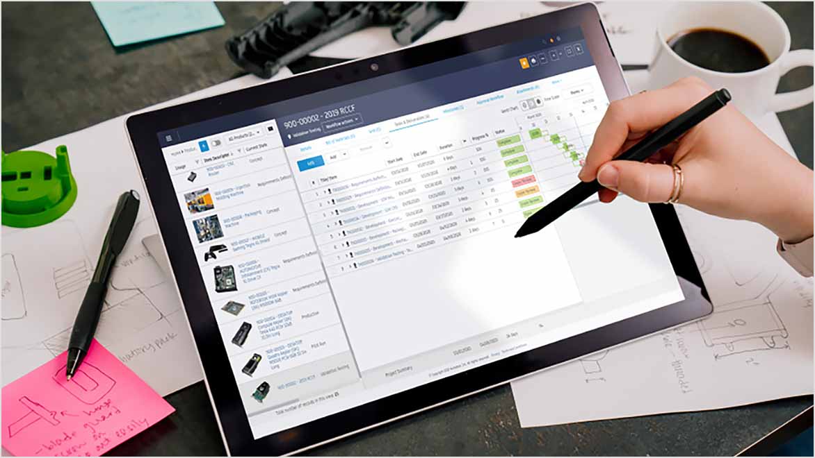
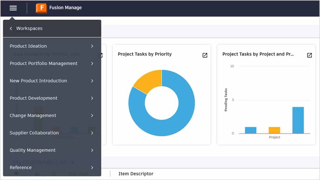
Autodesk Fusion 360 Manage is a cloud-based PLM solution that connects people, processes, and data throughout the product life cycle. It offers a wide range of functionalities, including:

  • Project Management: Fusion 360 Manage allows teams to plan, execute, and monitor projects effectively. Users can create tasks, assign resources, and track progress in real-time, ensuring that projects stay on schedule.
  • Change Management: The platform provides tools to manage engineering changes, ensuring that all stakeholders are informed and changes are documented and approved systematically.
  • Bill of Materials (BOM) Management: Autodesk Fusion 360 Manage allows users to create, manage, and track BOMs, ensuring that all components are accounted for throughout the product life cycle.
  • Collaboration Tools: With built-in collaboration features, teams can share information, communicate effectively, and work together seamlessly, regardless of their physical location.

By providing a centralised platform for collaboration and data management, Fusion 360 Manage enables teams to work together efficiently, leading to faster product development cycles and improved quality.

Integration with CAD Software

1. Fusion 360

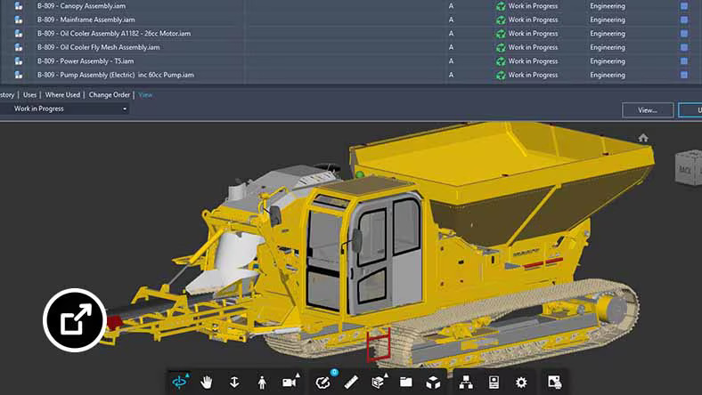
The integration of Fusion 360 with Autodesk Fusion 360 Manage is one of the most significant advantages of the platform. Fusion 360 is a powerful 3D CAD, CAM, and CAE tool that allows users to design, simulate, and manufacture products. The integration provides several key benefits:

    • Real-Time Collaboration: Users can manage design data directly within the PLM environment, facilitating real-time collaboration on design changes. This ensures all stakeholders can access the latest information, reducing the risk of errors and miscommunication.
    • Design Iteration Tracking: Autodesk Fusion 360 Manage allows teams to track design iterations effectively. Users can see the history of changes made to designs, making it easier to revert to previous versions if needed.
    • Centralised Data Management: All design data, including models, drawings, and simulations, can be stored and managed within Fusion 360 Manage. This centralisation simplifies data retrieval and ensures that everyone is working with the most current information.

2. Inventor

For users of Autodesk Inventor, Autodesk Fusion 360 Manage provides powerful tools to manage complex assemblies and parts. The integration between Inventor and Fusion 360 Manage offers:

    • Enhanced Control Over Assemblies: Users can manage large-scale projects with confidence, knowing that they have a clear overview of the design hierarchy and dependencies. This visibility helps teams coordinate their efforts and avoid conflicts.
    • Revision Management: Autodesk Fusion 360 Manage allows users to manage revisions and changes to Inventor files systematically. This ensures that all changes are documented and approved, reducing the risk of errors in the final product.
    • Seamless Data Exchange: The integration enables seamless data exchange between Inventor and Fusion 360 Manage, ensuring that design data is always up-to-date and accessible to all team members.

3. AutoCAD

AutoCAD is one of the most widely used CAD software applications, particularly for 2D design and drafting. The integration of AutoCAD with Autodesk Fusion 360 Manage provides several advantages:

    • Document Management: AutoCAD users can manage drawings and related documents within the PLM framework. This ensures that all design data, including 2D drawings, specifications, and supporting documents, are organised and accessible from a single location.
    • Version Control: Fusion 360 Manage offers robust version control features, allowing users to track changes to AutoCAD files and ensure everyone is working with the latest version.
    • Collaboration on Designs: The integration facilitates collaboration among team members working on AutoCAD designs, enabling them to share feedback and make changes in real-time.

Integration with Autodesk Vault

Autodesk Vault is a data management solution that ensures secure storage, version control, and tracking of design data. Although there is no native integration between Vault and Fusion 360 Manage, third-party tools like CoolOrange PowerPLM bridge this gap effectively, enabling organisations to leverage the strengths of both platforms.

How CoolOrange PowerPLM Works

PowerPLM allows for seamless data exchange and process synchronisation between Vault and Fusion 360 Manage. It acts as a bridge, enabling the transfer of data and workflows between the two systems. Key functionalities of PowerPLM include:

    • Item and Process Transfers: PowerPLM automates the transfer of items and processes between Vault and Fusion 360 Manage, ensuring that data is accurately and efficiently transferred between the two platforms. This enhances data integrity and collaboration by eliminating manual data entry and reducing the risk of errors.
    • Sample Workflows: PowerPLM provides predefined workflows that can be customised to suit specific organisational needs. For example, it can automatically create items in Fusion 360 Manage when items in Vault change states or synchronise Engineering Change Orders (ECOs) between both systems. This ensures that design changes are reflected across platforms, maintaining consistency and accuracy throughout the product development process.
    • Bidirectional Synchronisation: The tool enables bidirectional synchronisation between Vault and Fusion 360 Manage. This means that changes made in one system can be automatically reflected in the other, keeping both platforms up-to-date and reducing the risk of data discrepancies.

Benefits of Integrating Vault with Fusion 360 Manage

The integration of Autodesk Vault with Fusion 360 Manage through PowerPLM provides numerous benefits:

    • Improved Data Integrity: By automating data transfers and synchronisation, organisations can maintain high data integrity, ensuring that all stakeholders are working with accurate and up-to-date information.
    • Streamlined Workflows: The integration simplifies workflows by reducing the need for manual data entry and minimising the risk of errors. Teams can focus on their core tasks rather than spending time on administrative duties.
    • Enhanced Collaboration: With all design data accessible from both Vault and Fusion 360 Manage, teams can collaborate more effectively, leading to improved communication and faster decision-making.

Integration with Upchain and Prodsmart

While specific details on the integration of Fusion 360 Manage with Upchain and Prodsmart were not highlighted in the search results, both platforms are known for enhancing collaboration and data management in product development.

Upchain

Upchain is a cloud-based PLM solution that connects teams and data across the supply chain. Its integration with Fusion 360 Manage would likely facilitate better visibility and control over product data, enabling teams to collaborate more effectively and make informed decisions throughout the product life cycle. Key features of Upchain include:

    • Centralised Data Repository: Upchain provides a centralised repository for all product data, making it easy for teams to access the information they need when they need it.
    • Real-Time Collaboration: Teams can collaborate in real-time, sharing feedback and making changes to designs quickly. This agility is crucial in today’s fast-paced product development environment.
    • Enhanced Visibility: Upchain offers tools for tracking project progress and monitoring key performance indicators (KPIs), providing teams with insights into their workflows and helping them identify areas for improvement.

Prodsmart

Prodsmart is a manufacturing execution system (MES) that provides insights into production processes. Integrating Fusion 360 Manage with Prodsmart can improve efficiency and data-driven decision-making throughout the manufacturing lifecycle. Key benefits of this integration include:

    • Real-Time Production Data: By connecting design data from Fusion 360 Manage with real-time production data from Prodsmart, organisations can optimise their manufacturing processes and identify bottlenecks.
    • Data-Driven Decision Making: The integration allows teams to make informed decisions based on real-time data, improving productivity and quality.
    • Streamlined Manufacturing Processes: By aligning design and manufacturing data, organisations can streamline their processes, reducing lead times and improving overall efficiency.

The Importance of Integration in Product Development

The integration of Fusion 360 Manage with various CAD software and data management solutions is crucial for modern product development. Here are some reasons why these integrations are essential:

1. Enhanced Collaboration

In today’s globalised world, teams often work across different locations and time zones. Integrating PLM with CAD software and data management solutions enables real-time collaboration, ensuring that all stakeholders can access the latest information and contribute to the project regardless of their location. This collaborative environment fosters innovation and accelerates product development.

2. Improved Data Management
Autodesk Fusion 360 Manage

Managing product data effectively is critical for successful product development. Integrating Fusion 360 Manage with tools like Autodesk Vault, Upchain, and Prodsmart ensures that all data is organised, accessible, and up-to-date. This reduces the risk of errors, minimises data silos, and enhances overall data integrity.

3. Streamlined Workflows

Integrations help streamline workflows by automating data transfers and synchronising processes. This reduces the need for manual data entry and minimises the risk of errors, allowing teams to focus on their core tasks and improving overall efficiency.

4. Better Decision-Making
Autodesk Fusion 360 Manage

Access to accurate and up-to-date data is essential for informed decision-making. By integrating various systems, organisations can ensure decision-makers have access to the information they need to make timely and effective decisions, ultimately leading to better project outcomes.

Ready to Transform Your Product Development Process?

Autodesk Fusion 360 Manage is a powerful PLM solution that offers seamless integration with Autodesk’s suite of CAD software and data management solutions. By connecting with tools like Fusion 360, Inventor, AutoCAD, Vault, Upchain, and Prodsmart, Fusion 360 Manage provides a comprehensive platform for managing product lifecycles and optimising product development processes. These integrations enhance collaboration, streamline workflows, and improve data integrity, enabling organisations to bring products to market faster and with greater success.

For design professionals looking to stay ahead of the curve, understanding and leveraging these integrations is crucial. By adopting a fully integrated approach to product development, organisations can achieve new levels of efficiency and innovation, setting themselves apart in today’s competitive market.

Get the best prices on Autodesk software.

Get skilled up and enroll in an Autodesk training course

Setup, libraries, programming and consulting services

Contact Us

Contact us to find out how we can help your business. Fill out the form below, by live chat, phone or email.

P: 1800 490 514 |  E: [email protected]

Connected Design

Design Consulting Autodesk Gold Partner
about design consulting Moving at the Speed of Business

VIEW MORE

Maximising CNC Efficiency with Autodesk Inventor and Fusion CAM Setup and Training Services

Autodesk Inventor

Maximising CNC Efficiency with Autodesk Inventor and Fusion CAM Setup and Training Services

Autodesk Inventor and Fusion CAM offer powerful tools to enhance CNC machining efficiency through streamlined workflows, advanced toolpath generation, and high-efficiency roughing. Design Consulting specialises in expert setup, post-processing, and training services to help manufacturers fully leverage these capabilities.

By integrating CAD and CAM functionalities, Autodesk’s solutions eliminate the need for multiple tools, reduce data translation issues, and enable advanced machining techniques. This integration supports seamless production, minimises errors, and fosters team collaboration. In fact, manufacturers using integrated CAD/CAM solutions have seen up to a 30% reduction in design-to-manufacturing time and a 25% increase in productivity.

In this blog post, we’ll explore how you can enhance CNC efficiency through expert Inventor and Fusion CAM setup, post-processing, and training services, ultimately boosting profitability and product quality in today’s competitive landscape.

How Do These Solutions Improve Efficiency?

1. Autodesk Inventor

Autodesk Inventor is renowned for its robust capabilities in mechanical design, simulation, and tooling. When it comes to CNC machining, Inventor’s integration allows for precise and efficient toolpath generation, directly influenced by the CAD model. This means any design changes are automatically updated in the toolpath, reducing errors and saving valuable time.

2. Fusion CAM

Fusion 360 stands out with its CAM functionality, providing an all-in-one platform that combines design, engineering, and manufacturing capabilities. Fusion CAM offers a diverse range of machining strategies, from 2.5-axis milling to complex 5-axis operations. The software’s ability to directly connect to CNC machines streamlines the workflow from design to fabrication, ensuring that your projects are both accurate and timely.

3. Inventor Nesting

Inventor Nesting works seamlessly within the Inventor environment, providing a high-level solution for optimising sheet metal and flat stock designs. This tool not only helps in maximising material utilisation but also significantly cuts down on waste, which is a crucial factor for cost-effective manufacturing.

The Benefits of Setting Up Inventor or Fusion CAM with Design Consulting

1. Customised Setup and Configuration

At Design Consulting, we understand that every manufacturing setup is unique. That’s why we offer customised services that tailor Inventor and Fusion CAM to perfectly fit your specific machinery and production needs. By optimising the software settings and configurations, we ensure that you get the most out of your CNC machines.

2. Associative Link Between Design and Machining

One of the standout features of using Inventor and Fusion CAM is the associative link between the design models and the machining toolpaths. Any modifications made to the design are automatically reflected in the toolpaths. This dynamic link minimises the need for manual updates and reduces the potential for errors, leading to smoother production runs and higher quality products.

3. Expert Post-Processor Customisation

The post-processing phase in CNC machining translates your CAD/CAM toolpaths into machine-understandable code (G-code). Design Consulting provides expert post-processor customisation services, ensuring that the generated code is optimised for your specific CNC machines, thereby enhancing efficiency and reducing turnaround times.

4. Training and Support

Implementing new software tools requires not just technical setup but also ensuring that your team is fully capable of utilising these tools. Design Consulting offers comprehensive training sessions tailored to your needs, conducted by certified experts. These training sessions cover everything from basic operations to advanced machining techniques, empowering your team to leverage Autodesk Inventor and Fusion CAM effectively.

Our ongoing support and maintenance services ensure that your operations continue to run smoothly and any potential issues are addressed promptly, allowing you to maintain peak productivity.

Unlock Your CNC Potential with Design Consulting's Autodesk Inventor and Fusion CAM Expertise

Integrating Autodesk Inventor and Fusion CAM into your CNC workflows with the help of Design Consulting not only enhances your operational capabilities but also provides a significant competitive edge in the market. By reducing material waste, minimising errors, and improving overall efficiency, our setup, post-processing, and training services equip you with everything needed to excel in today’s dynamic manufacturing landscape.

Explore more about how Design Consulting can transform your CNC operations by visiting our CNC posts page.

Contact Us

Contact us to find out how we can help your business. Fill out the form below, by live chat, phone or email.

P: 1800 490 514 |  E: [email protected]

Connected Design

Design Consulting Autodesk Gold Partner
about design consulting Moving at the Speed of Business

VIEW MORE

Connected Visual Design with Autodesk Product Design & Manufacturing Collection

Sportscar driving on a futuristic road Moving at the Speed of Business
Design Consulting Product Design Manufacturing Collection Moving at the Speed of Business

Connected Visual Design With Autodesk Product Design & Manufacturing Collection

Introduction to Visualisation With Autodesk Product Design & Manufacturing Collection

Autodesk Product Design & Manufacturing Collection is a comprehensive suite of software tools designed for manufacturers, product designers, and engineers. The collection includes a range of software applications, including Autodesk Inventor, Fusion 360, Nastran, 3ds Max, Navisworks, and Recap. These tools are designed to work together seamlessly, enabling users to create and visualise designs with ease.

One of the key benefits of the Autodesk Product Design & Manufacturing Collection is its ability to facilitate connected visual design. This means that the software tools in the collection work together to provide users with a holistic view of their designs, from initial concept to final product.

In this blog, we will explore some of the key features of the Autodesk Product Design & Manufacturing Collection that enable connected visual design, including photo rendering, shared views, simulation, project management collaboration, and 3D laser scan visualisation.

connected visual design with 3ds max in the Product Design & Manufacturing Collection for manufacturers visualising products

Photo Rendering in Autodesk Inventor

Photo rendering is an important aspect of visual design, as it enables designers to create realistic and detailed images of their designs. Autodesk Inventor, one of the software tools included in the Autodesk Product Design & Manufacturing Collection, includes powerful photo rendering capabilities.

Autodesk Inventor’s photo rendering tools enable users to create high-quality, photorealistic images of their designs. The software includes a range of lighting and material options, enabling users to customise the look and feel of their designs.

In addition, Autodesk Inventor’s photo rendering tools are integrated with its modelling tools, enabling users to create and edit their designs in real-time as they render them. This enables designers to quickly make changes to their designs and see how they will look in real-time.

Autodesk Inventor connected visual design photo rendering Product Design Manufacturing Collection Moving at the Speed of Business

Shared Views and Presentation Environment in Autodesk Inventor

In addition to its photo rendering capabilities, Autodesk Inventor also includes features that enable users to share their designs with others. The software’s Shared Views feature enables users to share their designs with others, regardless of whether they have Autodesk Inventor installed on their computer.

Using Shared Views, users can share their designs with others via a web link. This enables designers to collaborate with others and receive feedback on their designs from a wider range of stakeholders.

In addition, Autodesk Inventor includes a Presentation Environment feature, which enables users to create interactive presentations of their designs. This feature enables designers to showcase their designs in a more engaging and interactive way, helping to communicate the value of their designs to others.

Autodesk Inventor connected visual design using shared views in the Product Design & Manufacturing Collection

Photo Rendering in Fusion 360

Fusion 360 is another software tool included in the Autodesk Product Design & Manufacturing Collection that includes powerful photo rendering capabilities. The software includes a range of lighting and material options, enabling users to create realistic and detailed images of their designs.

In addition, Fusion 360 includes a cloud rendering feature, which enables users to render their designs in the cloud.

This means that users can send their rendering jobs to the cloud, where they will be processed using powerful cloud-based hardware. This enables users to quickly and easily create high-quality, photorealistic images of their designs without having to invest in expensive hardware.

Autodesk Fusion 360 photo rendering connected visual design Product Design & Manufacturing Collection

Photo Rendering in Navisworks

Navisworks is a project management software tool included in the Autodesk Product Design & Manufacturing Collection. The software is designed to facilitate collaboration and project management across the entire product design process.

In addition to its project management capabilities, Navisworks also includes powerful photo rendering tools. This enables users to create high-quality, photorealistic images of their designs, helping to communicate the value of their designs to stakeholders.

Navisworks rendering connected visual design wioth the Product Design & Manufacturing Collection

Simulation in Autodesk Inventor and Fusion 360

Simulation is an important aspect of the product design process, as it enables designers to test and validate their designs before they are manufactured. The Autodesk Product Design & Manufacturing Collection includes a range of simulation tools, including simulation capabilities in both Autodesk Inventor and Fusion 360.

Autodesk Inventor’s simulation tools enable users to simulate a range of scenarios, including stress analysis, deformation analysis, and motion analysis. This enables users to identify potential design flaws and make improvements before the product is manufactured.

Similarly, Fusion 360’s simulation tools enable users to simulate a range of scenarios, including structural, thermal, and fluid simulations. This enables users to gain a deeper understanding of how their designs will perform in the real world, helping to identify potential issues and make improvements.

Autodesk Fusion 360 connected visual design with simulation using the Product Design & Manufacturing Collection

Ready to Get Connected?

Save up to 20% on Autodesk Software and Services

Visualising Simulation Studies with Nastran and 3ds Max

In addition to simulation capabilities, the Autodesk Product Design & Manufacturing Collection includes tools that enable users to visualise and communicate their simulation studies. Nastran, a finite element analysis software tool, is included in the collection and enables users to perform advanced simulations.

Using Nastran, users can simulate a range of scenarios, including linear and nonlinear stress analysis, dynamic analysis, and heat transfer analysis. Once a simulation study is complete, users can use 3ds Max, a cinematic photo rendering and animation software tool included in the collection, to visualise the results.

This means that users can create high-quality, photorealistic animations of their simulation studies, helping to communicate their findings to others. This is particularly useful for designers who need to communicate their findings to non-technical stakeholders, such as executives or investors.

Nastran simulation connected visual design with Product Design & Manufacturing Collection

Simulation with 3ds Max

While 3ds Max is primarily known for its capabilities in creating 3D models and animations, it also includes powerful simulation tools that can be used to test and validate designs. These tools can be particularly useful for designers who are creating complex assemblies, such as mechanical or architectural systems.

One of the key simulation tools included in 3ds Max is the MassFX physics engine. This engine enables users to simulate realistic physical interactions between objects, such as collisions, gravity, and friction. Users can create simulations of objects falling, bouncing, and rolling across surfaces, and adjust the properties of the objects and the environment to create realistic effects.

Another simulation tool included in 3ds Max is the Particle Flow system. This system enables users to simulate the behavior of particles, such as dust, smoke, or debris. Users can create complex simulations of particle systems, adjusting the speed, direction, and density of the particles to create realistic effects.

In addition to these tools, 3ds Max also includes a range of plugins and add-ons that can be used to enhance its simulation capabilities. For example, the ThinkingParticles plugin enables users to create complex particle simulations, while the FumeFX plugin can be used to simulate smoke and fire.

Overall, the simulation tools included in 3ds Max can be a valuable resource for designers who need to test and validate their designs before they are manufactured. By creating simulations of complex systems, designers can identify potential problems and make adjustments before the design is finalized, helping to ensure that the final product meets the needs of its users.

It is important to note that while 3ds Max includes powerful simulation tools, it is not a dedicated simulation software like Nastran or Inventor. Therefore, it may not be suitable for all types of simulations and may require additional plugins or tools to create more complex simulations.

3ds max simulation connected visual design with Product Design Manufacturing Collection Moving at the Speed of Business

Cinematic Photo Rendering and Animations in 3ds Max

3ds Max is a cinematic photo rendering and animation software tool included in the Autodesk Product Design & Manufacturing Collection. The software includes powerful rendering capabilities, enabling users to create high-quality, photorealistic images of their designs.

In addition, 3ds Max includes a range of animation tools, enabling users to create complex animations of their designs. This is particularly useful for designers who need to create animations of their designs for marketing or instructional purposes.

Visualising 3D Laser Scans with Recap

Recap is a 3D scanning software tool that is included in the Autodesk Product Design & Manufacturing Collection. It enables users to create detailed 3D scans of physical objects, which can then be imported into other software tools for further processing.

One of the primary ways that Recap is used in the collection is to import 3D scans into other design software tools, such as Autodesk Inventor or Fusion 360. Once the scan data has been imported into these tools, designers can use it to create precise 3D models of the scanned objects.

For example, a designer might use Recap to create a 3D scan of an existing object, such as a machine part. The scan data can then be imported into Inventor, where the designer can create a 3D model of the part. This can be useful for designers who need to create replacement parts or make modifications to existing designs.

In addition to Inventor and Fusion 360, Recap data can also be imported into other software tools included in the Product Design & Manufacturing Collection. For example, the scan data can be imported into 3ds Max, where it can be used to create detailed visualisations and animations of the scanned objects.

Recap data can also be imported into Navisworks, which is a powerful project management and collaboration tool. By importing scan data into Navisworks, designers can create detailed 3D models of existing structures or environments, which can be used to plan construction projects or renovations.

Overall, Recap is a powerful tool that can be used to create detailed 3D scans of physical objects, which can then be imported into other software tools in the Product Design & Manufacturing Collection. This can be useful for designers who need to create precise 3D models of existing objects, or for those who need to plan construction projects or renovations using detailed 3D models of existing structures or environments.


Recap scans can be imported into several other software tools included in the Autodesk Product Design & Manufacturing Collection, including AutoCAD with specialized toolsets.

AutoCAD with specialized toolsets is a version of AutoCAD that includes additional features and tools designed for specific industries, such as architecture, engineering, and construction. It includes toolsets such as Architecture, Electrical, Mechanical, and MEP, among others.

By importing Recap scans into AutoCAD with specialized toolsets, designers can use the scan data to create precise 2D and 3D models of existing structures or environments. For example, the Architecture toolset includes features such as walls, doors, windows, and stairs, which can be used to create detailed architectural plans based on the scan data. Similarly, the Mechanical toolset includes tools for creating 3D models of mechanical components based on the scan data.

In addition to AutoCAD with specialized toolsets, Recap scans can also be imported into other software tools included in the Product Design & Manufacturing Collection, such as Nastran and Simulation Mechanical. These tools are used for advanced simulation and analysis of complex mechanical systems, and by importing scan data into these tools, designers can create precise 3D models of existing systems and components.

Recap scans can also be imported into Navisworks, which is a powerful project management and collaboration tool. By importing scan data into Navisworks, designers can create detailed 3D models of existing structures or environments, which can be used to plan construction projects or renovations.

Overall, Recap scans can be imported into a variety of software tools included in the Autodesk Product Design & Manufacturing Collection, including AutoCAD with specialized toolsets, Nastran, Simulation Mechanical, and Navisworks. This enables designers to create precise 2D and 3D models based on scan data, as well as perform advanced simulation and analysis of complex systems and components.

Bringing in 3D Models into 3ds Max and Navisworks

Connected visual design refers to the process of using various software tools to create and visualise 3D models of products or structures in a connected, integrated way. The Autodesk Product Design & Manufacturing Collection includes several software tools that can be used for connected visual design, including 3ds Max and Navisworks.

3ds Max is a powerful tool for creating highly detailed 3D models, as well as visualisations and animations of those models. By importing designs from other software tools, such as Inventor or Fusion 360, into 3ds Max, designers can create highly detailed visualisations of their products or structures. This can be useful for creating marketing materials or for visualising how products will look in real-world environments.

One of the key benefits of using 3ds Max for connected visual design is its ability to create highly realistic photo-renderings and animations. The software includes a range of tools and features for creating realistic lighting, textures, and materials, which can help designers create highly realistic visualisations of their designs. This can be particularly useful for designers who need to create realistic images or animations for marketing materials or presentations.

Navisworks, on the other hand, is a powerful project management and collaboration tool that is designed for use in the construction industry. It allows designers and project managers to create detailed 3D models of buildings or other structures, which can be used to plan and manage construction projects.

By importing 3D designs from other software tools, such as Inventor or Fusion 360, into Navisworks, designers can create highly detailed 3D models of their structures or environments. These models can then be used to plan construction projects or to identify potential issues or clashes in the design.

In addition to its project management and collaboration features, Navisworks also includes tools for creating realistic visualisations of designs. The software includes a range of photo-rendering and animation tools, which can be used to create highly realistic visualisations of buildings or other structures. This can be useful for creating marketing materials or for visualising how buildings or structures will look in real-world environments.

Overall, the Autodesk Product Design & Manufacturing Collection includes several software tools that can be used for connected visual design, including 3ds Max and Navisworks. By importing designs from other software tools into these applications, designers can create highly detailed and realistic visualisations of their products or structures, as well as manage construction projects and collaborate with other team members.

Exporting Navisworks to 3ds Max

To export Navisworks models to 3ds Max for further visualization such as photo rendering and animation, you can use the FBX file format. First, open your Navisworks model and select the objects you wish to export. Then, go to the “Add-Ins” tab and click on “Export FBX”. In the Export FBX dialog box, select the appropriate options such as the file location and units, and click “Export”. Once exported, open 3ds Max and import the FBX file. You can then apply textures, materials, and lighting to the model and use the software’s rendering and animation tools to create high-quality visuals and animations.

Compare Visualisation in Product Design & Manufacturing Collection

Software Title

Visualisation Tool

Key Features

Autodesk Inventor

Photo Rendering

• Realistic rendering of 3D designs

• Supports a variety of materials, textures, and lighting options

• Ability to create exploded views and animation

Autodesk Inventor

Shared Views and Presentation Environment

• Share designs with others and receive feedback

• Collaboration and commenting tools

• Ability to create presentations with interactive features

Autodesk Fusion 360

Photo Rendering

• Cloud rendering for faster rendering times

• Realistic rendering of 3D designs

• Supports a variety of materials, textures, and lighting options

Autodesk Simulation

Inventor

• Ability to simulate mechanical, thermal, and fluid flow properties

• In-product simulation analysis

• Interactive result visualisation

Autodesk Simulation

Fusion 360

• Cloud-based simulation analysis

• Ability to simulate mechanical, thermal, and fluid flow properties

• Interactive result visualisation

Autodesk Nastran

Visualise Simulation Studies

• Advanced simulation analysis capabilities

• Ability to simulate a wide range of materials and physical properties

• Interactive result visualisation

Autodesk Navisworks

Photo Rendering

• Realistic rendering of 3D models

• Ability to create animations and walkthroughs

• Collaboration and commenting tools

Autodesk Navisworks

Project Management and Collaboration

• Ability to create highly detailed 3D models of buildings or structures

• Identify potential issues or clashes in the design

• Collaboration and commenting tools

Autodesk Navisworks

5D Scheduling

• Create and manage construction schedules

• Ability to simulate construction sequences and identify potential issues

• Collaboration and commenting tools

Autodesk 3ds Max

Cinematic Photo Rendering and Animations

• Highly realistic photo-rendering and animation capabilities

• Supports a variety of materials, textures, and lighting options

• Advanced animation capabilities

Autodesk Recap

Visualise 3D Laser Scans with 3D Models

• Ability to create detailed 3D scans of physical objects

• Import scans into other software tools for further processing

• Integration with AutoCAD with specialised toolsets for modelling and visualisation

Ready to get your Visualisations Connected?

Discover how Autodesk Product Design & Manufacturing Collection can streamline your workflow, increase productivity, and optimise your design process. 

Get up to 20% Off Software or Services!

Contact us to find out how much money you can save on software, training or other services. Fill out the form below, by live chat, phone or email.

P: 1800 490 514 |  E: [email protected]

Connected Design

Sportscar driving- on a futuristic road

Connected Design with Product Design & Manufacturing Collection

Click a link below to learn more about Connected Design using the Autodesk Product Design & Manufacturing Collection 

VIEW MORE

Connected Factory Design with Autodesk Product Design & Manufacturing Collection

Connected Factory Design Moving at the Speed of Business
Design Consulting Product Design Manufacturing Collection Moving at the Speed of Business

Connected Factory Design with Autodesk Product Design & Manufacturing Collection

The Benefits of Connected Factory Design with Autodesk Product Design & Manufacturing Collection

In today’s competitive manufacturing landscape, it’s crucial for companies to design and build factories that are efficient, cost-effective, and adaptable to changing market demands. With the help of advanced technology, such as Autodesk’s Product Design & Manufacturing Collection, Autodesk Inventor, AutoCAD Architecture, and Navisworks, manufacturers can streamline their factory design process, reduce errors, and improve productivity.

In this blog post, we’ll explore the benefits of using Autodesk’s Product Design & Manufacturing Collection, Inventor, AutoCAD Architecture, and Navisworks using the Factory Design Utilities and how these tools are connected. We’ll also discuss real-world applications of connected factory design and how it can empower manufacturers to stay ahead of the competition.

Introduction to Connected Factory Design with Autodesk

Connected factory design refers to the use of advanced software tools to create a cohesive, streamlined design process for factories. This approach involves integrating various design and simulation tools to create a single, unified workflow. Autodesk’s Product Design & Manufacturing Collection is a powerful suite of software tools that allows manufacturers to create a connected factory design process.

Benefits of Using Product Design & Manufacturing Collection for Factory Design

The Product Design & Manufacturing Collection includes several powerful tools that can help manufacturers design and simulate their factories with greater efficiency and accuracy. Here are some of the key benefits of using these tools for factory design:

  1. Streamlined Design Process: Autodesk’s tools allow manufacturers to create a connected factory design process that integrates various design and simulation tools. This approach can help reduce errors and streamline the design process, resulting in faster time-to-market.

  2. 3D Modeling: With Autodesk Inventor, manufacturers can create 3D models of their factories, allowing them to visualize and optimize their designs before construction begins. This can help reduce costs and ensure that the factory meets all functional requirements.

  3. Building Design Optimization: AutoCAD Architecture provides a suite of powerful tools for building design optimization. This includes features such as automated documentation, advanced rendering, and collaboration tools, which can help manufacturers create optimized building designs.

  4. Factory Design and Simulation: Navisworks allows manufacturers to create detailed simulations of their factories, including machinery, equipment, and workflows. This can help identify potential issues before construction begins and ensure that the factory operates efficiently once it’s up and running.

factory design suite 2 Moving at the Speed of Business

Enhancing Factory Design with Navisworks and Factory Design Utilities

Navisworks and Factory Design Utilities are two key tools within the Product Design & Manufacturing Collection that can help manufacturers enhance their factory design process. Navisworks allows for detailed factory simulation, while Factory Design Utilities provides a suite of tools specifically designed for factory design.

Some of the key features of these tools include:

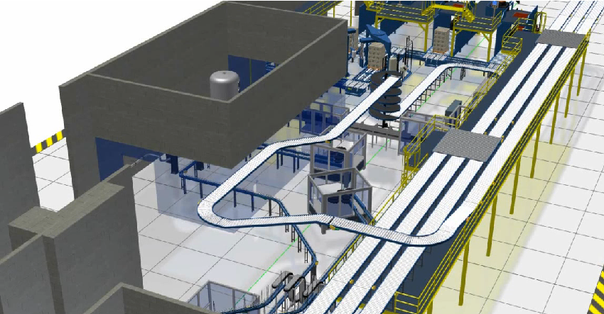
  1. Factory Design Utilities: This tool provides a suite of powerful tools specifically designed for factory design, including conveyor design, layout optimization, and factory equipment libraries.

  2. Navisworks: Navisworks allows manufacturers to create detailed simulations of their factories, including machinery, equipment, and workflows. This can help identify potential issues before construction begins and ensure that the factory operates efficiently once it’s up and running.

Factory Design Utilities AutoCAD Moving at the Speed of Business

Ready to Get Connected?

Save up to 20% on Autodesk Software and Services

Connecting the Tools for Seamless Factory Design

One of the key advantages of Autodesk’s Product Design & Manufacturing Collection is that it allows manufacturers to connect various tools within the suite to create a seamless factory design process. For example, manufacturers can use Navisworks to simulate their factory design, then use Factory Design Utilities to optimize the layout and equipment design, before using Inventor to create detailed 3D models of the factory.

Factory Design Utilities 1 Moving at the Speed of Business

Real-world Applications of Connected Factory Design

Connected factory design has numerous real-world applications across a wide range of industries. For example, automotive manufacturers can use these tools to design and build factories that are optimized for the production of electric vehicles. Pharmaceutical companies can use these

Top 5 Reasons to use Connected Factory Design with Product Design & Manufacturing Collection instead of only AutoCAD or Inventor

  1. Layout Optimization: One of the biggest advantages of using Factory Design Utilities is its ability to optimize the layout of a factory. This software enables users to create 3D factory models and simulate their operations, allowing them to test different layout configurations and optimize them for better productivity and efficiency.

  2. Equipment Design: Factory Design Utilities provides specialized tools for designing and placing factory equipment, including conveyors, robots, and other machinery. This software enables users to create accurate 3D models of equipment, test its functionality, and optimize its placement for maximum efficiency.

  3. Collaboration Tools: Factory Design Utilities also provides collaboration tools that allow multiple stakeholders to work on the same project simultaneously. This feature enables designers, engineers, and other team members to collaborate on designs, exchange feedback, and make changes in real-time, improving the overall quality of the design.

  4. Real-world Applications: Factory Design Utilities has been specifically designed for factory design and is widely used in real-world applications. This software has been used by manufacturers in various industries, including automotive, pharmaceutical, and consumer goods, to create efficient and effective factory designs.

  5. Time-to-Market: The use of Factory Design Utilities can help reduce the time-to-market of a product by enabling manufacturers to design and optimize their factories quickly and efficiently. This software allows manufacturers to test and optimize their designs before they are built, reducing the need for costly and time-consuming modifications during the construction phase.

Factory Design Utilities Commands

Command/ToolFactory Design UtilitiesAutoCADInventorNavisworks
LayoutFactory tab > Create Layout
Edit LayoutFactory tab > Edit Layout
Auto-RouteFactory tab > Auto-Route
Auto-PlaceFactory tab > Auto-Place
Factory ComponentsFactory tab > Factory Components
Insert DWG/DXFFactory tab > Insert DWG/DXF
Align and DistributeFactory tab > Align and DistributeModify tab > AlignAssemble tab > AlignModify tab > Align
Grounding and SurfaceFactory tab > Grounding and Surface
Place EquipmentFactory tab > Place Equipment
Factory AssetsFactory tab > Factory AssetsNavisworks Manage tab > Manage Assets
Assets from InventorFactory tab > Assets from InventorNavisworks Manage tab > Import Inventor
Asset PropertiesFactory tab > Asset PropertiesNavisworks Manage tab > Asset Properties
VisualizeFactory tab > VisualizeVisualize tab > RenderStudio tab > Create Studio RenderNavisworks Manage tab > Visualize
AnalyzeFactory tab > AnalyzeNavisworks Manage tab > Analyze
OptimizeFactory tab > OptimizeNavisworks Manage tab > Optimize
Sync to FactoryFactory tab > Sync to FactoryNavisworks Manage tab > Synchronize
Add to Factory AssetsFactory tab > Add to Factory AssetsNavisworks Manage tab > Add to Assets
Update from Factory AssetsFactory tab > Update from Factory AssetsNavisworks Manage tab > Update from Assets
Factory ReportsFactory tab > Factory ReportsNavisworks Manage tab > Report

Case Studies

Here are some case studies for Autodesk Factory Design Utilities and Factory Design Suite:

  1. FLSmidth: FLSmidth, a global supplier of cement and minerals processing equipment, used Autodesk Factory Design Suite to design and optimize a new manufacturing facility in China. The software allowed them to create a 3D model of the plant layout and simulate different scenarios to identify the most efficient design.

  2. Pratt & Whitney: Pratt & Whitney, a manufacturer of aircraft engines, used Autodesk Factory Design Suite to design a new production facility in Singapore. The software allowed them to visualize the facility in 3D and optimize the layout to reduce material handling and increase efficiency.

  3. Hekuma: Hekuma, a manufacturer of injection molding systems, used Autodesk Factory Design Suite to design a new factory in Germany. The software allowed them to create a 3D model of the facility and simulate different scenarios to optimize the layout for efficiency and safety.

  4. Sandvik Mining: Sandvik Mining, a global supplier of mining equipment and services, used Autodesk Factory Design Suite to design a new manufacturing facility in South Africa. The software allowed them to visualize the layout in 3D and optimize the design to reduce material handling and increase productivity.

  5. The Heinz Endowments: The Heinz Endowments, a nonprofit organization focused on environmental sustainability, used Autodesk Factory Design Utilities to design a new sustainable manufacturing facility in Pittsburgh. The software allowed them to create a 3D model of the facility and simulate different scenarios to optimize the design for energy efficiency and sustainability.

These case studies demonstrate the diverse range of industries and applications for Autodesk Factory Design Utilities and Factory Design Suite, and the software’s ability to improve efficiency, productivity, and sustainability in manufacturing and production facilities.

Ready to get your Factory Design Connected?

Discover how Autodesk Product Design & Manufacturing Collection can streamline your workflow, increase productivity, and optimise your design process. 

Get up to 20% Off Software or Services!

Contact us to find out how much money you can save on software, training or other services. Fill out the form below, by live chat, phone or email.

P: 1800 490 514 |  E: [email protected]
Connected Design

Connected Factory Design Moving at the Speed of Business

Connected Design with Product Design & Manufacturing Collection

Click a link below to learn more about Connected Design using the Autodesk Product Design & Manufacturing Collection 

VIEW MORE

Connected PCB Design with Autodesk Product Design & Manufacturing Collection

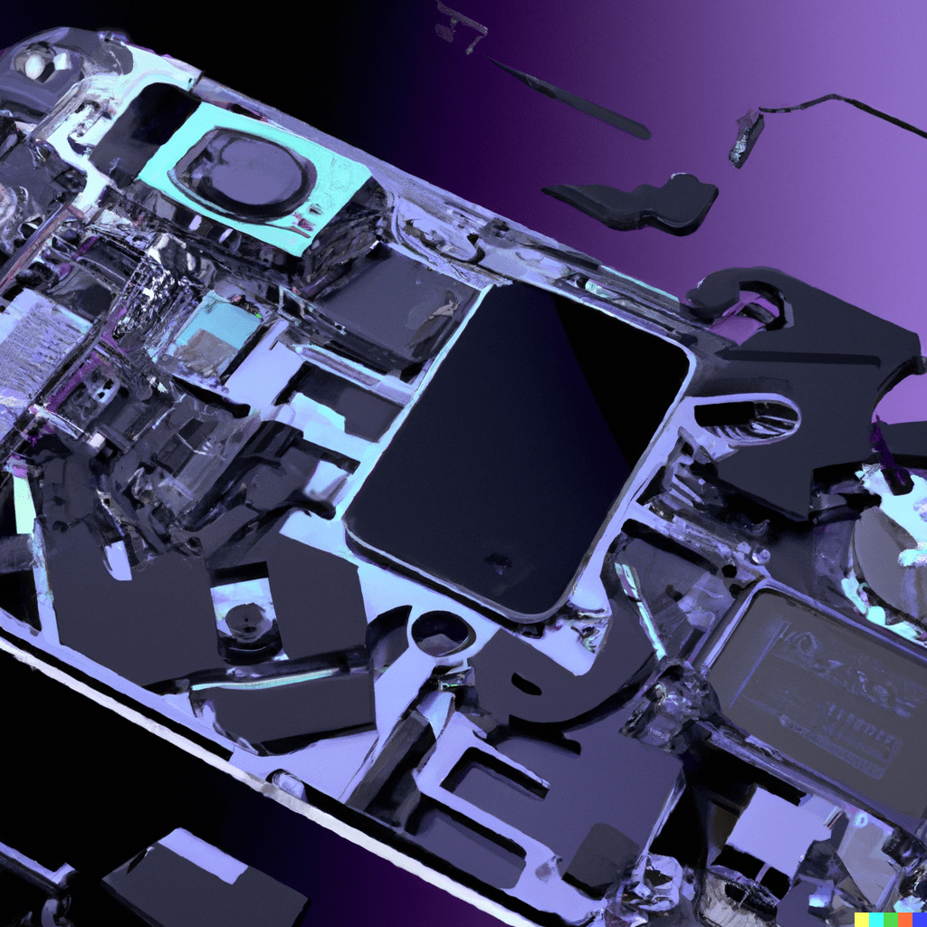
Smartphone exploded view showing the pcb Moving at the Speed of Business
Design Consulting Product Design Manufacturing Collection Moving at the Speed of Business

Connected PCB Design with Autodesk Product Design & Manufacturing Collection

Revolutionising Electronics Design: How Autodesk Inventor's PCB Interoperability Tools are Changing the Game

Autodesk Inventor is a powerful CAD software that offers a range of advanced features for mechanical and electrical design. One of the most valuable features for electronic designers is the ability to work with printed circuit boards (PCBs) directly in the software. With Autodesk Inventor’s PCB interoperability tools, users can streamline their design process and create more accurate designs

How to Achieve Connected Design with Autodesk Inventor and Eagle (Fusion 360)

Are you looking to streamline your printed circuit board (PCB) design workflow? Look no further than Autodesk’s connected design solution between Inventor and Eagle. This powerful combination allows for seamless collaboration between mechanical and electrical design teams. Autodesk Eagle, now a part of Fusion 360, is a popular PCB design tool that offers a range of powerful features to create schematics, layout designs, and manufacturing outputs. By integrating Eagle with Inventor, designers can easily incorporate PCBs into their mechanical assemblies and optimize the fit and function of their designs. 

One key advantage of using Inventor and Eagle together is the ability to maintain a “single source of truth” for your design data. With the integration, design changes in one tool can be automatically propagated to the other, reducing the risk of errors and ensuring consistency across the design process. 

Another benefit of this connected design approach is the ability to visualize the PCB and its components in a 3D mechanical assembly context. This allows designers to check for potential interferences, optimize the placement of the PCB and its components, and ultimately achieve a more efficient and cost-effective design.

To get started with connected design between Inventor and Eagle, simply import your Eagle board file into Inventor. From there, you can place the PCB into your assembly and start working on the integration with your mechanical components. Changes made to the PCB in Eagle will be reflected in Inventor, and vice versa.

Picture2 Moving at the Speed of Business

Inventor's PCB Interoperability Tools

Inventor offers a suite of tools for working with PCBs, including:

ECAD-MCAD Collaboration

This tool allows electrical and mechanical designers to work together seamlessly by importing 3D models of the PCB into Inventor. This tool eliminates the need for physical prototypes and enables designers to test the fit of the PCB in the mechanical assembly.

PCB layout import

Inventor can import and view PCB layouts from other software tools such as Eagle, Altium, and OrCAD. This feature allows designers to view their designs in a 3D environment and make any necessary changes before finalizing the design.

Design rule checking

Inventor offers a comprehensive design rule checking tool that allows designers to check their PCB designs against a set of predefined rules. This feature ensures that the design meets industry standards and helps identify any potential errors before the manufacturing process.

Export to Manufacturing

Once the design is complete, Inventor can export the PCB design to the manufacturing process. This feature ensures that the design is accurate and ready for production.

Picture1 Moving at the Speed of Business

Ready to Get Connected?

Save up to 20% on Autodesk Software and Services

Streamlining Design Workflows: Importing and Exporting Data Between Autodesk Inventor and Eagle (Fusion 360)

Importing and exporting data between Autodesk Inventor and Eagle is a critical function for any engineer working on a connected design project. Fortunately, the process is straightforward, thanks to the seamless integration between the two applications.

To import an Eagle board into Inventor, the first step is to create a new board assembly in Inventor. Next, click on the Eagle PCB Import command and select the .brd file. Inventor will then import all the PCB data, including the component placement and board outline.

Exporting data from Inventor to Eagle is equally easy. Simply open the board assembly in Inventor and select the Eagle PCB Export command. This will generate a .brd file that can be imported into Eagle, complete with all the board data and component placement.

One critical aspect of importing and exporting data between these two applications is ensuring that the design rules and constraints are consistent. Any discrepancies in the design rules can cause significant issues, including board failures or electrical shorts.

Fortunately, Autodesk has developed a comprehensive set of tools to ensure that data is accurately exchanged between Inventor and Eagle. For example, the Eagle board data is automatically translated into the Inventor format, ensuring that all dimensions and placement data are consistent.

Seamless Integration: How Autodesk Inventor and Fusion 360 Work Together for Streamlined PCB Design

Autodesk Inventor and Fusion 360 are both powerful design tools that can be used for a wide range of applications. While Inventor is known for its advanced 3D design capabilities, Fusion 360 is a comprehensive product development platform that allows designers and engineers to work together in a collaborative environment.

One of the ways that Inventor and Fusion 360 work together is through their interoperability with PCB design software. In particular, Fusion 360 includes an integrated PCB design tool called Eagle that can be used to create schematics and layouts for printed circuit boards. By leveraging the power of Eagle and the design capabilities of Inventor and Fusion 360, designers can create complex PCB designs with ease.

One of the key benefits of using Inventor and Fusion 360 for PCB design is the ability to work in a connected design environment. This means that designers can collaborate in real-time with other members of their team, including electrical engineers, mechanical engineers, and other stakeholders. This collaborative approach can help to streamline the design process and reduce errors, ensuring that the final product is of the highest quality.

Another advantage of using Inventor and Fusion 360 for PCB design is the ability to import and export data between the two platforms. This means that designers can easily move between the two tools, leveraging the strengths of each platform as needed. For example, designers can create a 3D model of a PCB in Inventor, then import the data into Fusion 360 to add electrical components and wiring.

To get started with using Inventor and Fusion 360 for PCB design, users should first become familiar with the basic workflows and tools of each platform. They should also explore the various integration points between the two tools, including the ability to import and export data, collaborate in a connected design environment, and use the integrated Eagle PCB design tool within Fusion 360.

Why Use Autodesk Inventor for PCB Design?

Autodesk Inventor’s PCB interoperability tools make it an ideal choice for electronic designers. The ability to work with both mechanical and electrical designs in the same software environment streamlines the design process and eliminates the need for multiple software tools. This feature also enables designers to test the fit of the PCB in the mechanical assembly, reducing the risk of errors and rework.

Additionally, Inventor’s ability to import and view PCB layouts from other software tools enables designers to work with existing designs and make any necessary changes in a 3D environment. This feature saves time and improves accuracy.

Finally, Inventor’s comprehensive design rule checking tool ensures that the design meets industry standards and identifies any potential errors before the manufacturing process. This feature reduces the risk of costly errors and ensures that the design is accurate and ready for production.

Conclusion

In conclusion, the interoperability between Autodesk Inventor and Fusion 360, along with the integrated Eagle PCB design tool, makes these tools an excellent choice for designers and engineers looking to create complex PCB designs. By working together in a connected design environment and leveraging the strengths of each platform, designers can create high-quality PCB designs in a fraction of the time it would take with other tools.

Ready to get your PCB Design Connected?

Discover how Autodesk Product Design & Manufacturing Collection can streamline your workflow, increase productivity, and optimise your design process. 

Get up to 20% Off Software or Services!

Contact us to find out how much money you can save on software, training or other services. Fill out the form below, by live chat, phone or email.

P: 1800 490 514 |  E: [email protected]

Connected Design

Smartphone exploded view showing the pcb Moving at the Speed of Business

Connected Design with Product Design & Manufacturing Collection

Click a link below to learn more about Connected Design using the Autodesk Product Design & Manufacturing Collection 

VIEW MORE

Connected Structural Design with Autodesk Product Design & Manufacturing Collection

Connected Structural Design Moving at the Speed of Business
Design Consulting Product Design Manufacturing Collection Moving at the Speed of Business

Connected Structural Design with Autodesk Product Design & Manufacturing Collection

Transforming Structural Design with Autodesk Product Design & Manufacturing Collection

The Autodesk Product Design and Manufacturing Industry Collection is a comprehensive set of software tools for designing and manufacturing products across various industries. This collection includes software for 3D design, engineering, and production, and it’s ideal for product designers and manufacturers. In this blog post, we will explore the connected structural design tools in Autodesk Inventor and how they can be used to design and analyse structures. We will also discuss how the structural designs from Inventor can be used in Plant 3D to design production plants, oil and gas projects, and how to export dwg or adsk file formats to AutoCAD.

Structural Design and Analysis Tools in Autodesk Inventor

Autodesk Inventor offers a range of structural design and analysis tools that enable users to create complex structures with ease. The software comes equipped with frame generator, sheet metal, and assembly modeling environment to facilitate the design of structural elements. These tools are ideal for designers and engineers who need to create robust and reliable structures.

Exporting dwg or adsk File Formats to AutoCAD

Autodesk Inventor offers the ability to export designs in dwg or adsk file formats to AutoCAD. This feature enables users to work with the designs in AutoCAD, which is useful for designers who need to create 2D drawings or for those who prefer working in AutoCAD. The process of exporting designs is straightforward and requires only a few clicks.

Structural Design in Plant 3D

Plant 3D is a specialized toolset of AutoCAD that allows users to design and analyse production plants, oil and gas projects, and other industrial structures. Users can utilise structural designs created in Inventor in Plant 3D to design various elements such as pipe supports, equipment, and structural steel. This feature enables designers to create a comprehensive 3D model that includes all the structural and mechanical elements of a plant.

Frame Generator

Frame Generator is a powerful tool in Autodesk Inventor that enables users to design and create structural frames with ease. This tool allows users to create complex frame structures using pre-defined structural shapes or custom shapes. The tool also provides the ability to create structural members with different cross-sections and apply various constraints to optimize the frame’s strength and stability.

Frame Analysis

Frame Analysis is a feature in Autodesk Inventor that allows users to analyse and optimize frame structures. This feature provides a comprehensive set of tools for analysing frames, including calculating the frame’s natural frequencies, calculating the stresses and displacements, and evaluating the frame’s stability. The tool also provides the ability to modify the frame’s design and re-run the analysis to optimise the frame’s performance.

Simulation

Autodesk Inventor offers simulation tools that enable users to simulate various types of mechanical and structural behavior, including structural analysis, motion analysis, and dynamic simulation. These tools allow users to evaluate the structural and mechanical performance of their designs, identify potential issues, and optimize their designs for better performance.

Ready to Get Connected?

Save up to 20% on Autodesk Software and Services

Nastran Structural Simulation Analysis

Nastran Structural Simulation Analysis is a comprehensive simulation tool in Autodesk Inventor that allows users to simulate and analyse complex mechanical and structural behaviour. This tool provides advanced simulation capabilities for analysing stress, deformation, vibration, and other mechanical behaviours. The tool also provides the ability to perform finite element analysis (FEA) to optimize designs for better performance.

Structural Design Workflow

The workflow from designing a structural design in Inventor to performing a frame analysis and Nastran structural analysis study involves several steps, which are as follows:

Step 1: Designing the Structural Design in Inventor

The first step is to create the structural design in Autodesk Inventor using tools such as Frame Generator, Sheet Metal, or Assembly Modelling Environment. The design can include various elements, such as beams, columns, braces, and trusses.

Step 2: Preparing the Model for Analysis

Once the structural design is created, the next step is to prepare the model for analysis. This involves assigning material properties, loads, and boundary conditions to the model. Material properties include properties such as modulus of elasticity, Poisson’s ratio, and density, while loads and boundary conditions can include forces, moments, supports, and constraints.

Step 3: Performing a Frame Analysis

The next step is to perform a frame analysis to evaluate the structural behaviour of the design. In Autodesk Inventor, Frame Analysis can be performed using the Frame Analysis Environment. This environment allows users to perform various types of analysis, including static, modal, and buckling analysis. Frame Analysis can be used to calculate natural frequencies, stresses, and deformations of the structure.

Step 4: Performing a Nastran Structural Analysis Study

If more advanced analysis is required, a Nastran Structural Analysis Study can be performed. Nastran is a finite element analysis software that is integrated into Autodesk Inventor. This tool provides advanced simulation capabilities for analysing stress, deformation, and other mechanical behaviours. It can also be used to perform more complex analyses, such as dynamic and thermal analysis.

Step 5: Optimizing the Design

Once the analysis is complete, the next step is to optimize the design based on the results of the analysis. This can involve modifying the structural design or adjusting the loads and boundary conditions to improve the performance of the design.

Step 6: Iterating the Process

Finally, the design process is iterated, with the model being adjusted and re-analysed until an optimal design is achieved. This can involve going back to Step 2 and re-defining the loads and boundary conditions, or adjusting the design in Inventor and re-analysing in the Frame Analysis or Nastran Structural Analysis Study environment.

In summary, the workflow from designing a structural design in Inventor to performing a Frame Analysis and Nastran Structural Analysis Study involves several steps, including preparing the model for analysis, performing the analysis, optimizing the design, and iterating the process until an optimal design is achieved. These tools in Inventor allow for the creation of complex structures and ensure their mechanical behaviour is analysed and optimized for performance.

Ready to get your Structural Design Connected?

Discover how Autodesk Product Design & Manufacturing Collection can streamline your workflow, increase productivity, and optimise your design process. 

Get up to 20% Off Software or Services!

Contact us to find out how much money you can save on software, training or other services. Fill out the form below, by live chat, phone or email.

P: 1800 490 514 |  E: [email protected]

Connected Design

Connected Structural Design Moving at the Speed of Business

Connected Design with Product Design & Manufacturing Collection

Click a link below to learn more about Connected Design using the Autodesk Product Design & Manufacturing Collection 

VIEW MORE

Connected Mechanical Design with Autodesk Product Design & Manufacturing Collection

Connected Mechanical Design 2 Moving at the Speed of Business
Design Consulting Product Design Manufacturing Collection Moving at the Speed of Business

Connected Mechanical Design with Autodesk Product Design & Manufacturing Collection

Streamlining Mechanical Design with Product Design & Manufacturing Collection: A Guide to Connecting Autodesk Inventor, Fusion 360, AutoCAD, and AutoCAD Mechanical

Mechanical design is an intricate process that requires the use of multiple software tools. Each software tool has its unique features, which are essential for creating a functional design. The Product Design & Manufacturing Collection from Autodesk brings together all the necessary tools for mechanical design. This collection includes Autodesk Inventor, Fusion 360, AutoCAD, and AutoCAD Mechanical. By using these tools together, mechanical design becomes more streamlined and efficient. In this guide, we will explore the benefits of using these tools in conjunction with each other and provide a step-by-step process on how to connect them for maximum efficiency.

Overview of Product Design & Manufacturing Collection

The Product Design & Manufacturing Collection from Autodesk is a comprehensive collection of software tools that are designed to streamline the product design process. The collection includes Autodesk Inventor, Fusion 360, AutoCAD, and AutoCAD Mechanical. These tools work together seamlessly, allowing engineers and designers to collaborate on projects and share data across platforms. By using these tools together, teams can reduce errors, improve accuracy, and speed up the design process.

The Benefits of Using Autodesk Inventor, Fusion 360, AutoCAD, and AutoCAD Mechanical Together

The benefits of using Autodesk Inventor, Fusion 360, AutoCAD, and AutoCAD Mechanical together are numerous. First, the tools provide a comprehensive set of features that cover all aspects of mechanical design, from 3D modeling to simulation to manufacturing. Second, the tools are designed to work together seamlessly, allowing teams to collaborate on projects and share data across platforms. Third, the tools are constantly updated and improved, ensuring that users always have access to the latest features and functionality.

Connecting Autodesk Inventor, Fusion 360, AutoCAD, and AutoCAD Mechanical

To connect Autodesk Inventor, Fusion 360, AutoCAD, and AutoCAD Mechanical, follow these steps:

Install all the software tools from the Product Design & Manufacturing Collection on your computer.

Open Autodesk Inventor and create a new part or assembly.

From the menu bar, select “Manage” and then select “Import/Export.”

From the dropdown menu, select the file format you wish to use (e.g., DWG, DXF, IGES).

Select the file you wish to import and click “Open.”

The file will be imported into Autodesk Inventor, and you can start working on it.

Using Autodesk Inventor, Fusion 360, AutoCAD, and AutoCAD Mechanical for Mechanical Design

Autodesk Inventor is a powerful 3D CAD software that is used for mechanical design. It allows designers to create 3D models of parts and assemblies, perform simulations, and generate documentation. Fusion 360 is a cloud-based CAD/CAM software that allows designers and engineers to collaborate on projects in real-time. AutoCAD is a 2D CAD software that is used for creating detailed drawings, and AutoCAD Mechanical is a 3D CAD software that is used for mechanical design.

Ready to Get Connected?

Save up to 20% on Autodesk Software and Services

Unlocking the Power of AnyCAD: Combining Autodesk Inventor, Fusion 360, and AutoCAD Mechanical for Seamless Mechanical Design

AnyCAD in Autodesk Product Design & Manufacturing Collection lets you transfer 3D models between different software platforms effortlessly, making collaboration on complex projects easier. AnyCAD enables you to link Autodesk Inventor, Fusion 360, and AutoCAD Mechanical to create an integrated mechanical and electrical design with automatic updates. The 2D detailing in AutoCAD Mechanical benefits from AnyCAD’s ability to import the Inventor model, maintaining a single source of truth for design data and reducing the risk of errors.

Front page Moving at the Speed of Business

AnyCAD and DWG Files

Autodesk Inventor and AutoCAD are powerful design tools for 3D and 2D design, respectively. With AnyCAD, users can import AutoCAD DWG files into Inventor and work with both 2D and 3D geometry. AnyCAD eliminates the need for manual conversions and allows for faster and more accurate design changes. It also enables users to work with annotations and other design details in both environments, improving collaboration and communication between stakeholders. Overall, AnyCAD streamlines the design process, making it more efficient and accurate.

inventor 2021 revit to inventor anycad 11 1024x1024 1 Moving at the Speed of Business

Combining all Designs from Fusion 360 and AutoCAD Mechanical into Autodesk Inventor

The Product Design & Manufacturing Collection from Autodesk offers a suite of powerful tools for designing and manufacturing products. One of the major benefits of this collection is the ability to seamlessly integrate designs from different software platforms, such as Autodesk Inventor, Fusion 360, and AutoCAD Mechanical. In this post, we’ll explore how to combine all designs from Fusion 360 and AutoCAD Mechanical into Autodesk Inventor.

Importing Fusion 360 designs

To import a Fusion 360 design into Inventor using Anycad, you first need to export the design as a STEP file from Fusion 360. In Fusion 360, select the design you want to export, go to the File menu, and select Export. Choose the STEP file format and save the file.

Next, open an Inventor assembly and go to the Anycad tab. Click on the Import command and select the exported STEP file. The Fusion 360 design will now be imported into the Inventor assembly, where you can combine it with other designs.

Importing AutoCAD Mechanical designs

To import an AutoCAD Mechanical design into Inventor using Anycad, you need to export the design as a DWG file from AutoCAD Mechanical. In AutoCAD Mechanical, select the design you want to export, go to the File menu, and select Save As. Choose the DWG file format and save the file.

Next, open an Inventor assembly and go to the Anycad tab. Click on the Import command and select the exported DWG file. The AutoCAD Mechanical design will now be imported into the Inventor assembly, where you can combine it with other designs.

Combining all designs in Inventor

Once you’ve imported the designs from Fusion 360 and AutoCAD Mechanical into Inventor, you can start combining them. You can use the assembly tools in Inventor to mate and constrain the different components, creating a complete 3D model. You can also use the drawing tools in Inventor to create 2D drawings and detailing.

Combining all Designs into AutoCAD Mechanical

When using the Product Design & Manufacturing Collection, it’s possible to combine the strengths of different software programs to create a more comprehensive mechanical design workflow. One example of this is using Autodesk Inventor to create a 3D mechanical model, which could have a Fusion 360 model linked into it.

Once the 3D model is complete, it can be imported into AutoCAD Mechanical to further refine the design and create detailed 2D drawings. AutoCAD Mechanical offers a range of powerful tools for creating mechanical drawings, including the ability to create and edit mechanical symbols, automate common tasks, and easily generate bills of materials.

To import the Inventor model into AutoCAD Mechanical, simply use the “Insert” command to bring the 3D model into the 2D workspace. Once the model is in place, you can use AutoCAD Mechanical’s powerful annotation tools to add dimensions, notes, and other details to your drawings.

It’s worth noting that AutoCAD Mechanical also has a range of built-in tools for working with Inventor files directly, including the ability to import Inventor assemblies and parts directly into the software. This can be a great way to leverage existing Inventor designs and incorporate them into your AutoCAD Mechanical workflows.

Overall, the combination of Inventor, Fusion 360, and AutoCAD Mechanical offers a powerful suite of tools for mechanical design and detailing. By leveraging the strengths of each software program, designers can create comprehensive mechanical designs and detailed 2D drawings with greater efficiency and accuracy.

Ready to get your Mechanical Design Connected?

Discover how Autodesk Product Design & Manufacturing Collection can streamline your workflow, increase productivity, and optimise your design process. 

Get up to 20% Off Software or Services!

Contact us to find out how much money you can save on software, training or other services. Fill out the form below, by live chat, phone or email.

P: 1800 490 514 |  E: [email protected]

Connected Design

Connected Mechanical Design 2 Moving at the Speed of Business

Connected Design with Product Design & Manufacturing Collection

Click a link below to learn more about Connected Design using the Autodesk Product Design & Manufacturing Collection 

VIEW MORE

Connected Design with Autodesk Product Design & Manufacturing Collection

Product Design & Manufacturing Collection IC Commercial New Single-user ELD Annual Subscription
Design Consulting Product Design Manufacturing Collection Moving at the Speed of Business

Connected Design with Autodesk Product Design & Manufacturing Collection

Connecting Autodesk Inventor with Other Software Tools for Efficient Design

Are you looking for ways to streamline your product design and manufacturing process? Autodesk Product Design & Manufacturing Collection which includes Autodesk Inventor, a powerful 3D modelling software, can be a game-changer for your business. Not only can Inventor help you create complex designs with ease, but it can also connect with other Autodesk software tools for a more efficient and integrated design process.

Here’s how Product Design & Manufacturing Collection and Inventor can connect with other Autodesk software tools to improve your design workflow:

Connected Design with Product Design & Manufacturing Collection

Inventor can be used in conjunction with other Autodesk software tools such as Revit, 3ds Max, and AutoCAD. This “connected design” approach allows for seamless data exchange between software applications, improving collaboration and reducing the risk of errors and delays.

Using Inventor and AutoCAD to improve Design and Collaboration

Inventor and AutoCAD can be used together to create 2D drawings of 3D models. This integration streamlines the design process and allows for quick changes to be made to drawings as the design evolves.

Collaboration in Navisworks

Models can be imported into Navisworks for simulation and analysis. This integration allows designers to evaluate the performance of their designs and identify potential issues before production begins.

Navisworks Factory Moving at the Speed of Business
Editing Properties in Vault

Connected Design with 3ds Max

Export 3D models to 3ds Max for high-quality rendering and visualization. This integration allows designers to create photorealistic images and animations of their designs, making it easier to communicate their vision to stakeholders and customers.

Autodesk Revit

Connecting Product Design & Manufacturing Collection to Revit

Inventor can import Revit models to create detailed designs for mechanical and electrical components. Revit models can also be exported to Inventor for further refinement.

Revit interoperability Moving at the Speed of Business

Autodesk Shared Views: Collaborate Easily with Stakeholders

Autodesk Shared Views is a cloud-based tool that enables users to share their designs and models with stakeholders in real-time. It simplifies the review process by allowing users to share a link to the Shared View, where reviewers can access the design directly in their browser. Shared Views supports multiple reviewers and provides markup tools for collaboration. The tool also includes version control features for tracking changes and viewing previous versions. Being cloud-based, Shared Views requires no software or hardware installation, making it accessible from any device with an internet connection.

How Autodesk Inventor Helps You Achieve BIM Interoperability

Autodesk Inventor simplifies BIM workflows and enhances collaboration with other stakeholders by providing BIM interoperability tools. These tools allow you to create, import and export BIM data in various formats, enabling you to work more efficiently with software like Revit and Navisworks. Inventor’s BIM Content Creation, BIM Content Import, BIM Project Review and BIM-to-Fabrication tools provide accurate and consistent designs. These tools can be used in conjunction with the Product Design and Manufacturing Industry Collection, which includes additional software tools. Start using Inventor’s BIM interoperability tools today to streamline your workflow and deliver better projects.

Ready to Get Connected?

Save up to 20% on Autodesk Software and Services

Revolutionizing Electronics Design: How Autodesk Inventor's PCB Interoperability Tools are Changing the Game

Autodesk Inventor is a powerful CAD software that offers a range of advanced features for mechanical and electrical design. One of the most valuable features for electronic designers is the ability to work with printed circuit boards (PCBs) directly in the software. With Autodesk Inventor’s PCB interoperability tools, users can streamline their design process and create more accurate designs.

Inventor’s PCB Interoperability Tools

Inventor offers a suite of tools for working with PCBs, including:

  • ECAD-MCAD Collaboration
  • PCB layout import
  • Design rule checking
  • Export to Manufacturing

Additionally, Inventor’s ability to import and view PCB layouts from other software tools enables designers to work with existing designs and make any necessary changes in a 3D environment. This feature saves time and improves accuracy.

Finally, Inventor’s comprehensive design rule checking tool ensures that the design meets industry standards and identifies any potential errors before the manufacturing process. This feature reduces the risk of costly errors and ensures that the design is accurate and ready for production.

Product Design & Manufacturing Collection Connected Matrix

SoftwareDescriptionFile TypeCommandImport/ExportLink
Inventor3D mechanical design software used for creating detailed product designs and engineering documentationIPT, IAMOPEN, MODEL, DRAWING, PUBLISHImport: DWG, DXF, STEP, IGES, SAT, CATIA, SolidWorks, Pro/E, NXExport: DWG, DXF, STEP, IGES, SAT, CATIA, SolidWorks, Pro/E, NX
AutoCAD2D and 3D computer-aided design software used for creating blueprints, schematics, and modelsDWG, DXF, DWFDRAWING, MODEL, VIEW, PLOTImport: DWG, DXF, DWF, PDF, STEP, SAT, IGES, STLExport: DWG, DXF, DWF, PDF, STL, OBJ, FBX
Fusion 360Integrated CAD, CAM, and CAE software used for product development and manufacturingF3D, IPT, IAMOPEN, MODEL, DRAWING, CAMImport: DWG, DXF, STEP, IGES, SAT, SolidWorks, Pro/E, NXExport: DWG, DXF, STEP, IGES, SAT, SolidWorks, Pro/E, NX
Alias AutoStudioIndustrial design software used for creating and visualizing product designsOBJ, STLOPEN, MODEL, RENDERImport: IGES, STEP, STL, OBJ, SolidWorks, CATIA, Pro/EExport: IGES, STEP, STL, OBJ, SolidWorks, CATIA, Pro/E
NavisworksProject review software used for 3D coordination, model analysis, and clash detectionNWD, NWFOPEN, APPEND, EXPORT, PUBLISHImport: DWG, DWF, DGN, IFC, SKP, FBX, 3DS, OBJExport: DWF, DWFx, NWC, NWF, FBX, 3DS, OBJ
      
HSMWorksIntegrated CAM software used for programming CNC machinesIPT, IAMSETUP, TOOLPATH, POSTImport: DWG, DXF, STEP, IGES, SAT, SolidWorks, Pro/E, NXExport: DWG, DXF, STEP, IGES, SAT, SolidWorks, Pro/E, NX
Nastran In-CADFinite element analysis (FEA) software used for simulating and analyzing product designsNAS, OP2OPEN, ANALYSIS, RESULTSImport: IPT,

Interoperability between design and analysis software

Import/Export: Inventor supports a variety of file formats for import and export, including STEP, IGES, and SAT. This flexibility allows for easy data exchange between Inventor and other software tools, improving collaboration and reducing errors.

Collaboration

By connecting Inventor with other Autodesk software tools, designers can create complex designs with ease, reduce errors and delays, and streamline the design process. With improved collaboration and data exchange, the product design and manufacturing process can be more efficient and cost-effective.

In conclusion, Autodesk Inventor is a powerful tool that can be used in conjunction with other Autodesk software tools to improve the design workflow. By following the tips outlined in this article, you can optimize your design process, reduce errors and delays, and create high-quality designs that meet your business needs.

Ready to get your Design Connected?

Discover how Autodesk Product Design & Manufacturing Collection can streamline your workflow, increase productivity, and optimise your design process. 

Get up to 20% Off Software or Services!

Contact us to find out how much money you can save on software, training or other services. Fill out the form below, by live chat, phone or email.

P: 1800 490 514 |  E: [email protected]

Connected Design

Design Consulting Product Design Manufacturing Collection Moving at the Speed of Business

Connected Design with Product Design & Manufacturing Collection

Click a link below to learn more about Connected Design using the Autodesk Product Design & Manufacturing Collection 

VIEW MORE

Connected Electrical Design with Autodesk Product Design & Manufacturing Collection

Connected Electrical Design Moving at the Speed of Business
Design Consulting Product Design Manufacturing Collection Moving at the Speed of Business

Connected Electrical Design with Autodesk Product Design & Manufacturing Collection

Autodesk Inventor and AutoCAD Electrical are two of the most popular software applications used in engineering design, particularly in electrical and electronic design automation. While each has its own strengths, combining these two powerful tools can lead to even greater design efficiency and productivity. In this article, we will explore how Autodesk Inventor and AutoCAD Electrical work together, focusing on the EMX project, syncing files, and how they can be combined with Fusion 360 for advanced PCB design.

Autodesk Inventor and AutoCAD Electrical: Combining Forces for Better Schematic Design

Introduction to Autodesk Inventor and AutoCAD Electrical

Autodesk Inventor is a 3D modeling software used primarily for mechanical engineering design. It allows users to create precise 3D models of mechanical parts, assemblies, and even entire machines. On the other hand, AutoCAD Electrical is a specialized software used for electrical engineering design. It provides a comprehensive set of tools for creating and modifying electrical control systems, wiring diagrams, and other related documentation.

The EMX Project: Enhancing Design Efficiency and Productivity

The EMX Project is an add-on for AutoCAD Electrical that enables users to create 3D representations of their electrical schematics in Autodesk Inventor. This makes it possible to visualize the electrical components in 3D space, making it easier to detect potential design issues before fabrication. The EMX project also allows users to import Inventor models into AutoCAD Electrical, giving them a more realistic representation of the actual components used in their designs.

Syncing Files Between Inventor and AutoCAD Electrical

Another advantage of using Autodesk Inventor and AutoCAD Electrical together is the ability to sync files between the two applications. This allows users to transfer 3D electrical harness models from Inventor to Electrical or vice versa, as well as easily update changes made in one application to the other. This seamless integration not only saves time but also ensures accuracy and consistency in design documentation.

Combining with Fusion 360: Taking PCB Design to the Next Level

Fusion 360 is a cloud-based CAD/CAM platform that allows users to collaborate on projects in real-time. It integrates with both Autodesk Inventor and AutoCAD Electrical, enabling users to bring their schematic designs into the 3D modeling environment of Fusion 360 for more advanced PCB design. This integration streamlines the design process and helps eliminate errors by providing a seamless workflow from schematic design to PCB layout and manufacturing.

How to Get Started with Autodesk Inventor and AutoCAD Electrical

To get started with Autodesk Inventor and AutoCAD Electrical, users need to have a basic understanding of electrical engineering principles and practices. They also need to have access to both software applications, as well as the EMX Project add-on for AutoCAD Electrical. Additionally, users can benefit from online training resources, tutorials, and forums provided by Autodesk to help them master the software.

Connected Electrical Design AutoCAD Electrical Schematics - Connected Electrical Design

Revolutionizing Electronics Design: How Autodesk Inventor's PCB Interoperability Tools are Changing the Game

Autodesk Inventor is a powerful CAD software that offers a range of advanced features for mechanical and electrical design. One of the most valuable features for electronic designers is the ability to work with printed circuit boards (PCBs) directly in the software. With Autodesk Inventor’s PCB interoperability tools, users can streamline their design process and create more accurate designs.

Picture2 Moving at the Speed of Business

Ready to Get Connected?

Save up to 20% on Autodesk Software and Services

How to Achieve Connected Design with Autodesk Inventor and Eagle (Fusion 360)

Look no further than Autodesk’s connected design solution between Inventor and Eagle. This powerful combination allows for seamless collaboration between mechanical and electrical design teams. Autodesk Eagle, now a part of Fusion 360, is a popular PCB design tool that offers a range of powerful features to create schematics, layout designs, and manufacturing outputs. By integrating Eagle with Inventor, designers can easily incorporate PCBs into their mechanical assemblies and optimize the fit and function of their designs. 

One key advantage of using Inventor and Eagle together is the ability to maintain a “single source of truth” for your design data. With the integration, design changes in one tool can be automatically propagated to the other, reducing the risk of errors and ensuring consistency across the design process. Another benefit of this connected design approach is the ability to visualize the PCB and its components in a 3D mechanical assembly context.

This allows designers to check for potential interferences, optimize the placement of the PCB and its components, and ultimately achieve a more efficient and cost-effective design. To get started with connected design between Inventor and Eagle, simply import your Eagle board file into Inventor.

From there, you can place the PCB into your assembly and start working on the integration with your mechanical components. Changes made to the PCB in Eagle will be reflected in Inventor, and vice versa.

Inventor’s PCB Interoperability Tools

Inventor offers a suite of tools for working with PCBs, including:

ECAD-MCAD Collaboration

This tool allows electrical and mechanical designers to work together seamlessly by importing 3D models of the PCB into Inventor. This tool eliminates the need for physical prototypes and enables designers to test the fit of the PCB in the mechanical assembly.

PCB layout import

Inventor can import and view PCB layouts from other software tools such as Eagle, Altium, and OrCAD. This feature allows designers to view their designs in a 3D environment and make any necessary changes before finalizing the design.

 Design rule checking

Inventor offers a comprehensive design rule checking tool that allows designers to check their PCB designs against a set of predefined rules. This feature ensures that the design meets industry standards and helps identify any potential errors before the manufacturing process.

Export to Manufacturing

Once the design is complete, Inventor can export the PCB design to the manufacturing process. This feature ensures that the design is accurate and ready for production.

Seamless Integration: How Autodesk Inventor and Fusion 360 Work Together for Streamlined PCB Design

https://www.autodesk.com/redshift/pcb-design-with-fusion-360/Autodesk Inventor and Fusion 360 are both powerful design tools that can be used for a wide range of applications. While Inventor is known for its advanced 3D design capabilities, Fusion 360 is a comprehensive product development platform that allows designers and engineers to work together in a collaborative environment.

One of the ways that Inventor and Fusion 360 work together is through their interoperability with PCB design software. In particular, Fusion 360 includes an integrated PCB design tool called Eagle that can be used to create schematics and layouts for printed circuit boards. By leveraging the power of Eagle and the design capabilities of Inventor and Fusion 360, designers can create complex PCB designs with ease.

One of the key benefits of using Inventor and Fusion 360 for PCB design is the ability to work in a connected design environment. This means that designers can collaborate in real-time with other members of their team, including electrical engineers, mechanical engineers, and other stakeholders. This collaborative approach can help to streamline the design process and reduce errors, ensuring that the final product is of the highest quality.

Another advantage of using Inventor and Fusion 360 for PCB design is the ability to import and export data between the two platforms. This means that designers can easily move between the two tools, leveraging the strengths of each platform as needed. For example, designers can create a 3D model of a PCB in Inventor, then import the data into Fusion 360 to add electrical components and wiring.

To get started with using Inventor and Fusion 360 for PCB design, users should first become familiar with the basic workflows and tools of each platform. They should also explore the various integration points between the two tools, including the ability to import and export data, collaborate in a connected design environment, and use the integrated Eagle PCB design tool within Fusion 360.

Why Use Autodesk Inventor for PCB Design?

Autodesk Inventor’s PCB interoperability tools make it an ideal choice for electronic designers. The ability to work with both mechanical and electrical designs in the same software environment streamlines the design process and eliminates the need for multiple software tools. This feature also enables designers to test the fit of the PCB in the mechanical assembly, reducing the risk of errors and rework.

Additionally, Inventor’s ability to import and view PCB layouts from other software tools enables designers to work with existing designs and make any necessary changes in a 3D environment. This feature saves time and improves accuracy.

Finally, Inventor’s comprehensive design rule checking tool ensures that the design meets industry standards and identifies any potential errors before the manufacturing process. This feature reduces the risk of costly errors and ensures that the design is accurate and ready for production.

In conclusion, the interoperability between Autodesk Inventor and Fusion 360, along with the integrated Eagle PCB design tool, makes these tools an excellent choice for designers and engineers looking to create complex PCB designs. By working together in a connected design environment and leveraging the strengths of each platform, designers can create high-quality PCB designs in a fraction of the time it would take with other tools.

Connected Design with Product Design & Manufacturing Collection

Click a link below to learn more about Connected Design using the Autodesk Product Design & Manufacturing Collection 

Ready to get your Electrical Design Connected?

Discover how Autodesk Product Design & Manufacturing Collection can streamline your workflow, increase productivity, and optimise your design process. 

Get up to 20% Off Software or Services!

Contact us to find out how much money you can save on software, training or other services. Fill out the form below, by live chat, phone or email.

P: 1800 490 514 |  E: [email protected]

Connected Design

Connected Electrical Design Moving at the Speed of Business

VIEW MORE

February 2023 Autodesk Update: What’s New

Autodesk
Autodesk Banner

Discover the latest news and new features from Autodesk, Click the links below for more information.

 AutoCAD and AutoCAD LT

 Architecture, Engineering & Civil Engineering

 Design & Manufacturing

 Media & Entertainment

 Admin resources and more

 More Information

Contact us on 1800 490 514, [email protected], by live chat or fill out the form below to get more information on how to best manage your Autodesk software.  Our team of experts have saved our clients thousands of dollars by helping them make smart decisions around how to best structure their investment in technology for maximum return on investment.   We’d be happy to audit your existing technology and recommend any changes that you could benefit from.


Contact Form Demo

VIEW MORE

Connect PDM and PLM with Autodesk

Fusion 360 Manage

Fusion 360 Manage

Fusion 360 Manage with Upchain: Cloud PLM and PDM that easily connects your data, people and processes. 

Fusion 360 Manage with Upchain is a true cloud-based SaaS solution for PDM and PLM. It delivers data and process management capabilities that enable manufacturers to digitally transform product development and collaboration workflows.

Fusion 360 Manage with Upchain allows you to connect your entire organisation, including your PLM and PDM systems. You can connect across multiple departments and international locations seamlessly, helping you bring your products to market with speed. Using cloud data and process management, you can:

  • Collaborate with internal and external stakeholders
  • Maintain one single source of truth with your latest product data

Why use Fusion 360 Manage With Upchain?

  • Get the full picture of all data from all sources. Integrate your processes and do more with your data.
  • Give everyone access to the data they need. Provide secure access to rich CAD data and solicit feedback from internal and external stakeholders without requiring CAD licenses for reviewers.
  • Collaborate without barriers across multiple teams, suppliers, customers or other partners any time, from any location.

What can you do with Fusion 360 Manage With Upchain?

  • Enjoy the flexibility to start quickly and scale easily over time.  Scale up and down as needed with modular processes and tailored workflows without having to implement customised coding.
  • Bring all your product data together in one place with an open system.  Create a single source of truth for all your product data including different file types with multi-CAD integrations and an open API.  Pull in upstream and downstream data from a range of systems including ERP or CRM systems.
  • Access your data from anywhere at any time. Access and review designs, view bill of material items, change lifecycle states, manage change orders and more all from a mobile device.

Fusion 360 Manage With Upchain Options

There are multiple versions of Fusion 360 With Upchain including:

ProfessionalFusion 360 Manage with Upchain Enterprise
For organisations with enterprise level needs. It has all the features of the professional version, plus a sandbox environment, it caters for third-party users, single sign-on and includes expanded cloud storage.


 Professional Fusion 360 Manage with Upchain Professional

The best option for power users and design engineers. Integrate your CAD tools with PDM. Create and manage BOMs, workflows, workspaces, templates and engineering changes.


fusion 360 manage with upchain standard thumb 788x444 1 Moving at the Speed of BusinessFusion 360 Manage with Upchain Standard
Suitable for both extended engineering and non-engineering teams. Harness the full capabilities of PLM. Define and manage your processes, workflows, engineering changes, workspaces and templates.

ParticipantFusion 360 Manage with Upchain Participant
Suitable for management, project stakeholders, data consumers and ticket-raisers. View documents, create and run reports, participate in workflows and view dashboards.

Not sure which option is best for you? Want more information?

Complete the enquiry form below or contact us to discuss Fusion 360 Manage with one of our experts.

VIEW MORE

Is the Automotive Industry just Big Tech on Wheels?

automotive big tech on wheels alias, iot, Autodesk alias autostudio, alias surface, alias concept

Is the Automotive Industry just Big Tech on Wheels?

With more and more tech going into cars with connected systems suing IoT, global positioning systems (GPS) and the technology for semi-autonomous and autonomous vehicles, will the automotive industry and big tech converge into one.

automotive big tech on wheels alias, iot, Autodesk alias autostudio, alias surface, alias concept

Transformation of the Automotive Industry

With the push for greener vehicles, more and more electronic systems and sensors, a connected digital supply chain, robotics, digital design, virtual reality and other technologies, it seems like we are already there.

automotive configurator tablet

Connected Automobiles

Our smartphones are already connected to vehicles via bluetooth and many cars have sim cards and these software platforms are all connected and can be used for consumer and industrial applications that can benefit the driver, passengers and payloads with a huge growth potential.

With these connected system, comes big data and analytics feeding into a centralised system give automobile manufacturers insights into how automobiles are being used and IoT diagnostics on component wear and tear, maintenance and failure

Manufacturing Big Tech Automotive

Most automotive factories are already using digital prototyping, design, machining and analysis software where the CAD models and metadata are used to in manufacturing processes, systems and machines to manufacture.

In the concept and design phases, virtual reality and high-end visualisation systems are used as standard, however, the automotive industry needs to be more agile and innovation to connecting not only cars to human interface devices but also other cars and systems and infrastructure that connect to cars. 

Automotive Needs More Programmers

automotive big tech iot

With today’s cars packed full of tech, the industry needs more programmers than ever to create in-built applications and integrate systems with external devices and applications.

“Today’s car infotainment systems use more than 10 million lines of code,” said Audi’s Member of the Board of Management for Marketing and Sales, Hildegaard Wortmann, speaking at NVIDIA’s GTC21 event this year. “That’s as much code as an entire vehicle needed just a few years ago.”

While the advantages of technology in cars and trucks is self-evident, the overhead to innovate, design and manage applications for essentially what is a mechanical smartphone device on wheels, adds to the cost of manufacturing and development.

What Does the Future Look Like for Automotive and Big Tech?

The Hollywood vision of driverless hybrid flying cars running on a anti-gravity fuel system is still far away but if we look at the gains we have made in the last 5 years, it’s probably not as far away as you think.

With over 50% of the workforce wanting to work from home these days, do we really need a car with all that tech if the days of being stuck in traffic for an hour or more are gone but we only have to imagine the magical drive down the ocean or trekking to the mountains and the justification of paying for all that tech and comfort makes sense in a car full of screaming kids. 

Autodesk alias autostudio, alias surface, alias concept

Contact Us

If you would learn more about Autodesk software, please contact us by calling on 1800 490 514, by filling out the form or clicking the live chat in the bottom right-hand corner.

Contact Us Moving at the Speed of Business

VIEW MORE

What’s New in Autodesk Inventor 2016

new rendering engine Moving at the Speed of Business

One of the biggest and best releases in CAD let alone Inventor. When Inventor 2015 was released I thought it was one the No.1 CAD system on the planet, Inventor 2016 cements it. Inventor blows away anything else on the market, add to that you get it in a Suite of other best of breed products and nothing else comes…

VIEW MORE

What is #TheFutureofMakingThings ?

inventor 2015 ray tracing Moving at the Speed of Business

Autodesk has launched The Future of Making Things. A vision of how they see future human and business interaction with technology when it comes to engineering, design, analysis and collaboration. At the Autodesk University Keynote address in December, 2014,  Jeff Kowalski, Autodesk SVP and Chief Technology Officer, discussed how Autodesk is looking at technology and design through the lens of…

VIEW MORE

Autodesk Inventor 2015 – Sheet Metal Enhancements

Autodesk Inventor Professional 3D mechanical CAD software

With sheet metal design being an integral part of many Inventor customers, the new features and enhancements are always taken with great interest, so here’s a video I put together: So What’s New in Sheet Metal for Inventor 2015 Rename End Of Part (EOP) to End Of Folded (EOF) for sheet metal parts Enhanced orientation control in…

VIEW MORE

What’s New in Autodesk Inventor 2015

gickr com 5542d49a 9ad1 a7d4 bdae 3533832576c1 Moving at the Speed of Business

Hybrid Parametric Direct Editing, N.U.R.B.S with T-Splines and more… Inventor 2015 is one of the best releases yet, unlike any other CAD tool on the market today because it not only delivers enhancements to existing tools and UI but adds new technology that makes this product so unique. There’s 2 big additions and many enhancements, so in this article…

VIEW MORE

Autodesk Announce CAM 360 – 1st Ever Cloud Based CAM

Autodesk have launched CAM 360 and you can try it here. It’s the only CAM that combines CNC Programming (Generator & Editing), Tool Path Simulation, and Design with real-time collaboration and online project and data management. It’s based on HSMWorks technology which they acquired about 13 months ago and comes with Fusion 360 too which will allow to to do 3D CAD…

VIEW MORE